Abstract
Two-dimensional (2D) ultrasound (US) images are widely used in minimally invasive prostate procedure for its noninvasive nature and convenience. However, the poor quality of US image makes it difficult to be used as guiding utility. To improve the limitation, we propose a multimodality image guided navigation module that registers 2D US images with magnetic resonance imaging (MRI) based on high quality preoperative models. A 2-step spatial registration method is used to complete the procedure which combines manual alignment and rapid mutual information (MI) optimize algorithm. In addition, a 3-dimensional (3D) reconstruction model of prostate with surrounding organs is employed to combine with the registered images to conduct the navigation. Registration accuracy is measured by calculating the target registration error (TRE). The results show that the error between the US and preoperative MR images of a polyvinyl alcohol hydrogel model phantom is 1.37 ± 0.14 mm, with a similar performance being observed in patient experiments.
INTRODUCTION
Prostate cancer is the common nonskin malignancy disease in men and the diagnosed number increase rapidly around the world. In many areas, such as Australia, China, the USA, and Western and Northern Europe, prostate cancer has a high mortality. For example, in 2014, it is estimated that the number of prostate cancer new cases will be 233,000, and 29,480 will die from it in the USA.1
Currently, transrectal ultrasound (TRUS) imaging and magnetic resonance imaging (MRI) of the prostate are the 2 main clinical methods for diagnosing, guiding needle biopsy of prostate cancer. TRUS guidance are widely used in many minimally invasive interventions, such as brachytherapy, cryotherapy, photothermal ablation,2 and photodynamic therapy3 for its nonionizing radiation, easy to operate, inexpensive, and widely accessible. However, it is always impossible and difficult to distinguish the tumors accurately in TRUS images.4 Therefore, MRI is the most widely used imaging modality to identify prostate cancer, because MRI provides high sensitivity to cancers with its high contrast soft tissue and easily recognizable regions. But, the complex magnetic environment and high price make it difficult to guide minimally invasive interventions.
One practical and low-cost solution is to register and fuse previously acquired MRI data to the TRUS, thus making use of the advantages of each modality.5 To date, some literatures describe a lot of registration methods which have been applied to deal with the registration problems between magnetic resonance (MR) images acquired at different times, and the ultrasound (US) images of the prostate with and without using an endorectal coil.6–8 Alterovitz et al6 and Bharatha et al8 used a biomechanical model to constrain the deformations of the prostate during the registration. Crouch et al9 registered CT images to MRI images which obtained with and without endorectal coil by using a registration method that can generate the volumetric finite element mesh of the prostate automatically under suitable boundary conditions.
A real-time registration method for US and MRI was described by Xu et al10 to be used for guiding prostate biopsies. In this method, they registered a 3-dimensional (3D) TRUS volume to the preacquired MRI volume using rigid transformation. The mean time for prostate biopsy using this method was 101 ± 68 seconds for a new target in patient studies. The registration accuracy of the method validated on phantoms was 2.4 ± 1.2 mm. A total of 101 other cases were used to test their method11 and the experimental results showed that the method made significant improvement to increase the rates of cancer detection during TRUS guided biopsies.
Narayanan et al12 carried out a further MR to TRUS registration research based on phantom. They used a set of multimodality prostate phantom which have fiducial markers (marked by embedding glass beads) for the registration. The mean fiducial registration error for the nonrigid registration was 3.06 ± 1.14 mm.
More recently, Mitra et al13 used a statistical measure of shape-contexts-based nonrigid registration method to register TRUS to MRI prostate images. By evaluating 20 pairs of prostate MRI and US images, the proposed method's registration accuracies are these 1.63 ± 0.48 mm for the average 95% Hausdorff distance and 1.60 ± 1.17 mm for mean target registration.
A model to image registration method was proposed by Hu et al14 that can align MRI and TRUS images of the prostate automatically. Using anatomical structures as landmarks to calculate the error for the registration, the final average root mean square registration error was 2.40 mm for each patient by doing 100 registration experiments.
Analyzing registration methods for prostate US-MR image, many methods could reach clinically registration accuracies, while the error of some methods was greater than 3 mm. Moreover, the speed of the most registration methods is not fast enough, whereas during the navigation procedures the registration of US and MRI images must be completed rapidly.
In this article, we try to build a surgical navigation module by rapidly registering the intraprocedure 2-dimensional (2D) US with preprocedure 3D MR images of the prostate and employing the fused images as image guidance for prostate brachytherapy. According to the registration, we can make sure that the US image matches the preoperative planning for brachytherapy which include 3D dose planning and route planning for inserting the needles. So, surgeons can use 2D US images to guide the insertion of radioactive seeds and get satisfactory curative effect. To realize this target, a 2-step registration method based on mutual information (MI) associated with tracking spatial information is proposed to register and fuse US and MR images during the procedure.
The organization of this article is shown as follows. In Materials and Method, the system components and methods are described in details. In Results section, the experimental results are presented and in discussion, the limitations, possible improvements, and future research directions are discussed.
MATERIALS AND METHOD
System Overview
The schematic of the surgical navigation system that based on registering 2D US to 3D MR images is shown in Figure 1.
FIGURE 1.
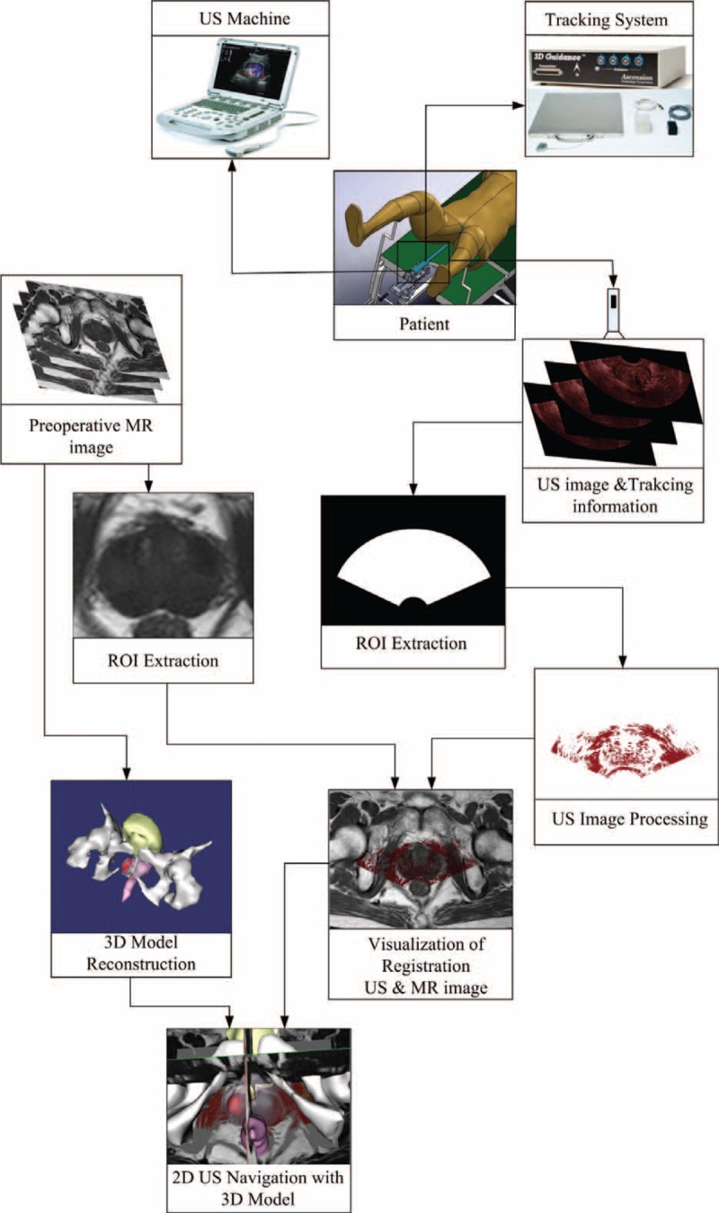
The schematic of surgical navigation module. The 3D MR images improve the interpretability of 2D US images by providing high quality context and reconstruct the 3D model of prostate. The orientation and position of the US probe are acquired by a tracking system to increase the registration speed, and together with 3D prostate model, fusion of registered US-MR images helps to navigate the brachytherapy surgery. 2D = 2-dimensional, 3D = 3-dimensional, MR = magnetic resonance, US = ultrasound.
Surgical navigation for brachytherapy surgical of the prostate is a complicated process, and the workflow for this procedure is proposed as follows.
Preoperative: Before the brachytherapy surgery, 3D MR images of the prostate are obtained and then these images are transferred to the computer. These images play a role in improving the quality of the 2D US images by providing appropriate anatomical structure context and reconstructing the 3D model of prostate with surrounding organs.
Perioperative: Prior to surgery after the patient being set up on the operating table, 2D US images containing 3D spatial position information are acquired. Then the preliminary registration is executed to register these 2D US images to the preoperative MR images. The purpose of the preliminary registration is not intended to register the US images accurately, but it can offer an appropriate starting point for subsequent registration process.
Intraoperative: The gradient ascent algorithm is used to maximize the MI metric15 to optimize the registration of the US and MRI images after the preliminary registration proposed in the perioperative step. The spatially aligned preoperative MR images and intraoperative US images are displayed and fused in real time to provide the navigation environment after registration.
3D US Calibration
To increase intraprocedure image registration speed, an electromagnetic locator device is employed to build a tracking system which can get the orientation and position information of the US probe. Then with the 3D space information, 3D US spatial calibration16 process is required to transform US images into the tracking system (TS) coordinate or world coordinate system (WCS). To realize this goal, the transformation
which transforms coordinates of US image into TS space is determined by
where
is the calibration matrix of 3D US images, which converts the coordinates of US voxel into the tracking device coordinate (the US probe is attached with tracking sensor),
is the matrix of tracking transformation, which transforms the tracking device space coordinates into TS space coordinates.
In this study, the rigid transformation is completed by using a 4 × 4 matrix
to transforms space S1 coordinates into space S2 coordinates. We define
 |
where
represents the rotation matrix which contains three 3 × 1 rotation vector, 01 × 3 the 1 × 3 zero vector, and
is the 3 × 1 translation vector. In the next section, the US image with 3D position tracking information is defined as USi. So the final transformation matrix
can be calculated by using the matrixes
(matrix of the tracking system) and
(matrix of the US calibration), the result is
 |
A Z-string 3D US freehand calibration (shown in Fig. 2A) procedure17 was used to calculate the transformation
. In this procedure, a Z-string phantom (shown in Fig. 2) which was made of 5 cotton strings (shown in Fig. 2C) supported by a Lucite frame (shown in Fig. 2B) was used to accomplish the calibration. The cross-section of the calibration phantom in the 2D US image was visible as 5 bright spots (shown in Fig. 2D). The central position of each bright spot in frame coordinate is computed, and then the calculated position is converted into tracking device coordinates. There is a corresponding point in US image space for each point in tracking device space. The transformation was calculated by using the least-squares minimization method. To get accurate calibration results, more than 20 US images were used to calculate the calibration transformation.
FIGURE 2.

3D US calibration phantom model. (A) Freehand calibration of 3D US, (B) the Z-string Lucite frame, (C) the arrangement of Z-string, and (D) the US image of the Z-string. 3D = 3-dimensional, US = ultrasound.
Two-Step Registration
Generally, the prostate differs in the size and shape when the US probe moved among the surgical procedure, but the changes do not vary so much. So in order to optimize our registration speed, we assume that the variation in size and shape does not change. Our discussion is also limited to rigid registration only as in common practice.
We outline the 2-step registration method to accelerate intraprocedure registration of 2D US images associated tracking information and 3D MR images (Fig. 3).
FIGURE 3.
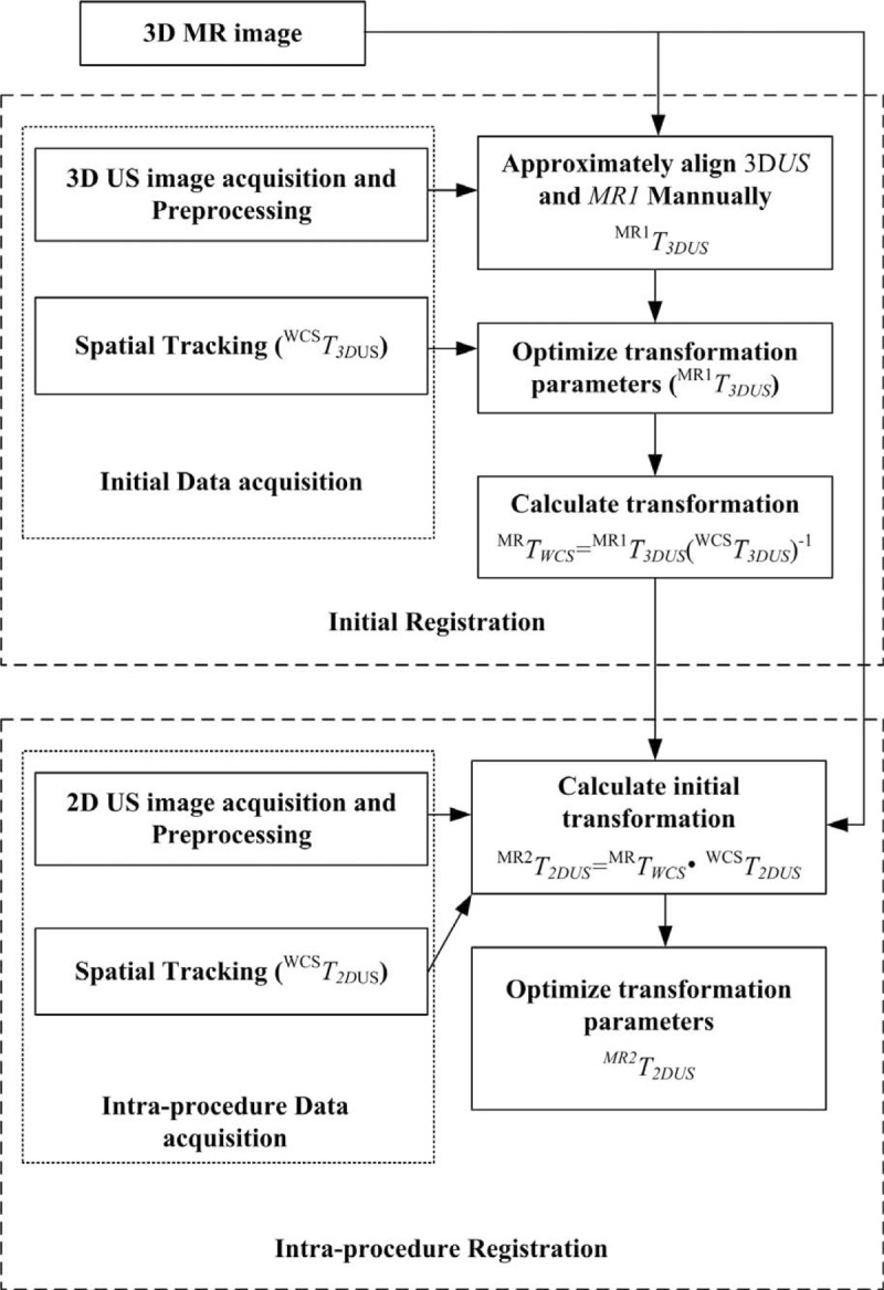
Proposed 2-step registration procedure.
Initial Registration
Registering images automatically need a lot of time, but when the starting point of the registration process is near to the result of final registration, the registration time can be minimized. In order to complete this goal, prior to intraprocedure registration of the US and MRI images the initial registration process is done to get a starting point that could be used in intraprocedure registration step.
When the patient is put on the operation table, a number of US images named initial US image is acquired. We use the 3D position tracking information transformation (indicated as
) to transform the 3D US images into the world coordinate system. Note that in this article, to each acquired US image an image preprocessing method is applied to extract the most interested features in the image. The acquired previously 3D MR images, and 3D US images at the same position of the prostate are recognized and matched. Then the coupled images, expressed as 3D US and MR1, are viewed using our Image Guided Brachytherapy System (IGBS) software and the US and MRI images are rotated and translated by hand until their positions are approximately aligned to obtain the transformation
. Then a MI-based registration method is applied to further refine this manual registration result and the refined result can generate a new transformation which is expressed as
. Next, we can calculate the transformation
that responsible for the transformation between the patient and MR images, the result is
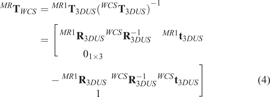 |
Intraprocedure Registration
The registration result acquired in the initial step is converted by using the tracking transformation matrix to get the new position which is set as a new starting point for the intraprocedure registration. Then a rapid MI technique20 is used to refine the registration.
In the intraprocedure registration procedure, there are 2 main procedures. The first one is to acquiring 2D US images, again augmented with spatial tracking information. The second one is to rapidly register 2D US images to the preprocedure 3D prostate MR images. Each (2D US) is marked based on its position. Then the spatial tracking information (indicated as the transformation
) is used to transform the intraprocedure US image into the world coordinate system. With the tracking information, each 2D US is associated with an MR image (MR2) which corresponds to the same position of the prostate. The coupled intraprocedure US and preprocedure MR images are roughly registered using the initial transformation.
 |
where
is generated by the initial registration. Then a gradient method to calculate the maximum of the MI metric is proposed to refine this registration to eliminate errors which caused by initial registration errors, patient motion, and errors of the tracking system.
In our 2-step registration method, the way to get the starting point for the automatic registration based on MI is the main difference between the 2 steps. This starting point is captured by using manually registration in the initial registration step, which needs user intervention. However in the intraprocedure registration step, a simple formula is proposed to compute the starting point automatically. Moreover, the point makes the intraprocedure registration more rapid and completely automatic for its position is much closer to the final registration result.
Prior Processing of US Image
Morphological gradient filter is an image processing process which can extract boundary feature under certain conditions. It contains 2 parts in this article. First, with the radius of 1 voxel a morphological erosion operation is used to extract anatomical boundary features in the US images. Second, a directional gradient magnitude filter is used to generate a gradient magnitude image to simplify the boundary feature with enough information for increasing registration speed. Before the registration, we used the median filter to reduce speckle noise of 2D US images, then depicted the region of interest of the prostate and removed the background in each US image by using thresholding method. The value of threshold was calculated as follows. When the median filter processing was finished, we used the morphological gradient filter to generate the gradient magnitude image. After that the gradient magnitude image was processed by using the threshold method to generate a boundary mask which covered prostate boundary. Next, the US image being median filtered and covered with the boundary mask was used to calculate mean value in intensity to get the threshold value. The results are presented in Figure 4.
FIGURE 4.
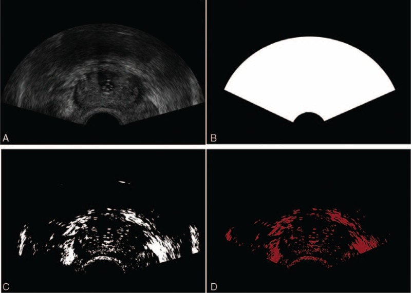
Prior processing of US image. (A) Initial US images, (B) ROI restricting, (C) thresholding process, and (D) final processed US images. ROI = region of interest, US = ultrasound.
Structure of the Surgical Navigation Module
The navigation module of the surgical is integrated into our IGBS software. The IGBS software was designed for helping to perform the prostate brachytherapy surgical which includes 3 main parts: 3D organs reconstruction, 3D conformal dose planning, and US navigation.
In order to make full use of open-source packages and build a surgical navigation system, the Visualization Toolkit (VTK) and the Insight Toolkit (ITK) are employed for image visualization and image registration, respectively. The custom VTK classes are also used to acquire 3D position tracking information and 2D US images. In the navigation module, every component including image registration, US image acquisition, and registered images visualization is integrated using multithreading techniques.
There are 4 threads running simultaneously in parallel on a workstation with multicore CPU (Intel Xeon E5–2630 V2, 2.6 GHz, 8192MB RAM) in the navigation module. Four individual tasks are run on each thread in this navigation program.
The registration results of 3D MR and 2D US images are displayed in the main thread. In this thread, the latest transformation generated by the registration thread is applied to transform the current 2D US image frame. At the same time, these US images have been transformed are fused with their corresponding 3D MR images.
The registration thread is used to rapidly register intraoperative 2D US images to 3D MRI images. The rapid MI registration method with the tracking information is employed to align the coupled 3D MRI and 2D US images. When the registration of 3D MRI and 2D US images is completed, the transformation generated from the registration result is transmitted to the main thread.
The US image acquisition thread is employed to capture dynamic 2D US image frames in real time and stores the frames in a circular buffer.
The tracking information acquisition thread is used to obtain the 3D position tracking information from the tracking device through a serial port, and converts it into a matrix containing four 4 × 1 vectors which includes the orientation and position information of the US probe. At the same time, a circular buffer is created to place the matrix.
Validation
Phantom Model
In order to accurately assess the precision of the registration method, a phantom model (shown in Fig. 5A) which is made of polyvinyl alcohol material18 is employed to take MRI and US images for the registration. In this model, we inserted 3 group metal seeds (shown in Fig. 5B) (produced by Seeds Biological Pharmacy (Tianjin) Ltd, made of titanium, the same shape and size with radioactive seed. Radioactive seed is a metal cylinder which is made up of titanium shell and sliver stick attached with I-125 or Pd-103 radioactive elements, 4.5 mm in length and 0.8 mm in diameter) into it as landmarks, because their phantom in the images is easily recognized. So, we can capture enough fiducial markers in only 1 slice of 2D US image to calculate the error. Then the target registration error (TRE) was calculated to make a thorough and complete evaluation about the registration method on a phantom model. In this procedure, an active pointer associated with the 3D position tracking system was used to measure the locations of the fiducial markers. In this article, the root-mean-square between the fiducial points’ position in MRI space and corresponding US image space was calculated as the TRE after the image registration.19
FIGURE 5.
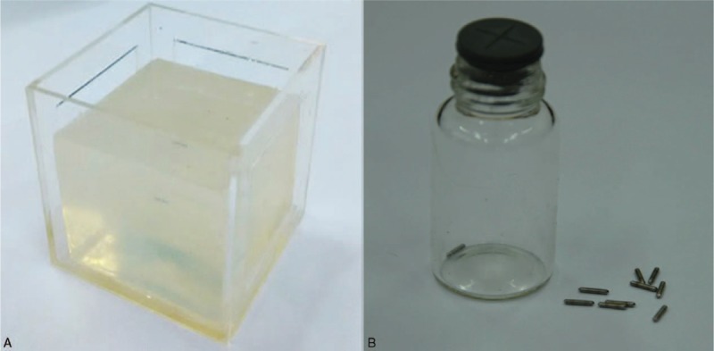
Phantom model. (A) polyvinyl alcohol (PVA) material, (B) metal seeds.
To conveniently compute the TRE according to the coupled fiducial pointers’ positions after US-MRI registration, all the positions of fiducial markers in 3D US image space were converted into 2D US image space by employing the transforming matrix
 |
. In this approach, there is an assumption that the information getting from the tracking system is precise, and the tracking error can also be ignored. In our case, the precision of the magnetic tracking system was ∼0.2 mm. The was calculated by
 |
where the transformation
is obtained from 2D US-MR registration,
is directly calculated from the tracking system,
is the matrix from 3D US calibration, and
is obtained from transforming 3D US image space into TS space in the process of 3D US image reconstruction.
Patient
In this article, we also used patients’ MRI and US images to validate the accuracy of the MI-based registration method. As the registration method would be used to navigate the prostate brachytherapy surgery, the registration speed is as significant as the accuracy. However, due to the artifacts and low signal to noise ratio, together with a mass of information to be dealt with, the registration may have incorrect result and cost a lot of time.
To overcome the difficulties and get better registration accuracy and speed, we did some image processing of the US images before the registration that described in section Prior Processing of US Image. Since the calculation of the MI using gradient optimization does not need the full voxels of the image, the sample voxels are selected randomly from the preprocessed images which represent the most remarkable feature to optimize MI. In this way, the cost of time would decrease a lot. After the registration of 3D MRI and 2D US images of the prostate, the TRE as described in Phantom Model was employed to validate the accuracy of the registration.
RESULTS
In this section, image acquisition and validation for 3D MR and intraoperative 2D US images registration results were described in detail.
Image Acquisition
Preoperative Image Acquisition
Six slices T2 weighted MR images of the prostate were acquired on each patient using a PHILIPS (Amsterdam, Netherlands)-FE9A9DC Nuclear Magnetic Resonance Spectrometer in the supine position. The resolution of 3D MR volumes was between 0.3 and 0.4 mm/pixel in plane, and the thickness of slice was 3.0 mm. Eighteen 2D US images with tracking information were acquired by using a Mindray (Shenzhen, China) DP-50 digital portable US machine. The median filter method was first used to process these US images to decrease speckle noise, and then according to the tracking information the 2D US images were reconstructed into 3D US images for the manually registration.
Intraoperative Image Acquisition
Intraoperative 2D US images associated with 3D position tracking information were acquired in real time during the “intra-procedure.” The median filter was also applied in this procedure, and the region of interest and background in each US image were extracted and removed, respectively.20
Phantom Studies
In this section, we used the phantom model (Fig. 6A) to validate our registration method. Prior to acquiring MR and US images, we inserted some metal seeds into the model to set as the landmarks for registration. Ten sets of MRI and US images of the phantom model were captured by using PHILIPS-FE9A9DC Nuclear Magnetic Resonance Spectrometer and Mindray DP-50 digital portable US machine, respectively. Then the 10 sets of MRI and US images were registered using our proposed 2-step registration method. Figure 7 shows the registration results.
FIGURE 6.

The phantom studies: (A) the phantom model, (B) the MR image of the model (the red + are metal seeds). (C) The US image of the model (the red + are metal seeds), (d) the result of the registration. MR = magnetic resonance, US = ultrasound.
FIGURE 7.
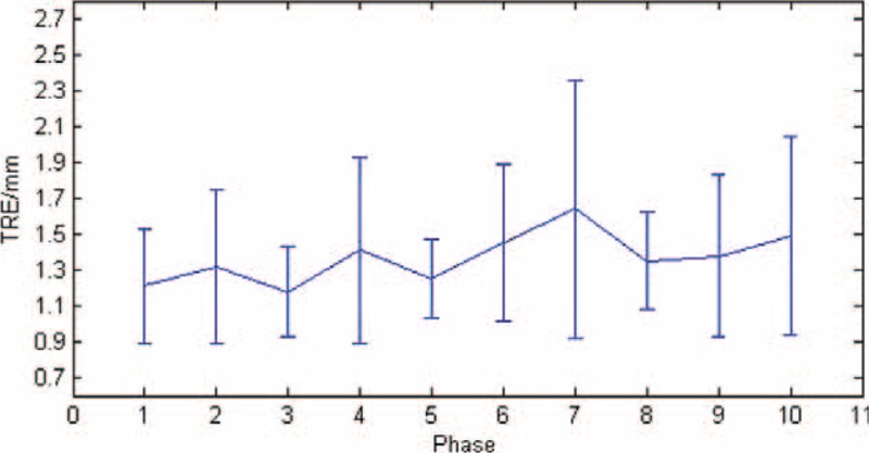
The target registration error (TRE) for the registration of phantom model.
Generally, the misalignment of landmarks in 2 registered images is calculated to evaluate the registration accuracy. In this study, we set the metal seeds (showed in Fig. 6B, C) as landmarks to calculate the TRE. After registering the MRI and US images, we calculated the TRE of each set images and drew a TRE figure as shown in Figure 7. The mean and standard deviation (SD) error value of the registration was 1.37 ± 0.14 mm.
Patient Studies
In patients studies, we obtained the MR and US images from 5 patients and calculated the average signal noise ratio of the MRI (23.21 ± 2.95 db) and US (20.05 ± 4.62 db) images, respectively, after the median filter processing. Note that all patients gave written informed consent for our research. After all images acquired, the registration process was performed offline. An MI-based registration method was used to register US and MR images spatially. The satisfactory result of the registration for 3D MR and 2D US images was selected to be shown in Figure 8.
FIGURE 8.
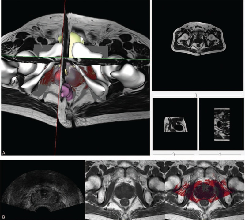
Registration result of 3D MR (gray) and 2D US (red) images of the prostate. (A) Registered 3D MR and 2D US images in 3D view. (B) The registration result (right) of registering US (left) and MR (middle) images in 2D view. 2D = 2-dimensional, 3D = 3-dimensional, MR = magnetic resonance, US = ultrasound.
To evaluate the registration accuracy for patient studies is very challenging, because in the prostate there are few identifiable landmarks. Moreover, due to the low quality and view limitation of the 2D US image, sometimes there are no sufficient landmarks to be selected in only 1 2D US image to assess the registration accuracy. In this article, each scanning 2D US image at all phase was checked carefully and the anatomical structures such as the urethra, sometimes the centers of tumors or lesions in the central gland or peripheral region were chosen as landmarks as illustrated in Figure 9.
FIGURE 9.
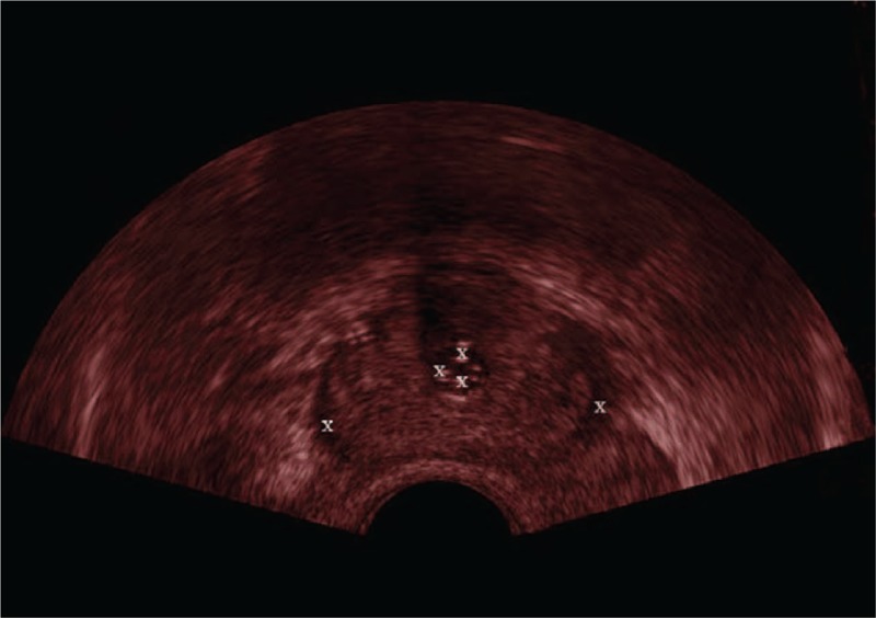
White symbols “X” are the landmarks in the ultrasound (US) image of the prostate.
After the registration, we calculated the TRE of each phase of the images and then averaged the results for each patient's image set and the mean ± SD was 2.52 ± 0.46 mm. The TRE results of the registration are shown in Figure 10.
FIGURE 10.
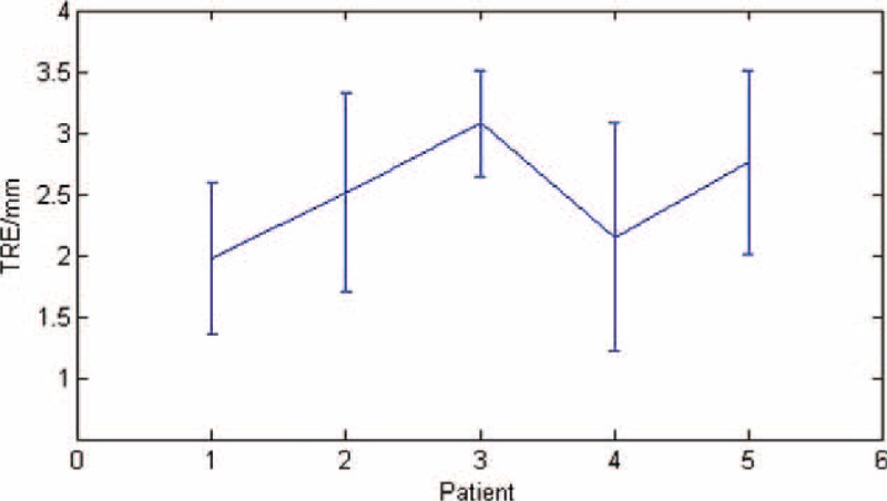
The target registration error (TRE) of the patients’ images registration.
DISCUSSION
An MI-based multimodality image registration method for registering intraoperative 2D US to preoperative 3D MR images is proposed in our navigation module which can make up for the lack on the vision during interventional procedures of brachytherapy surgical for prostate cancer. The interpretability of intraoperative US images is observably improved within the help of 3D MR images which can provide high quality anatomical context. The procedure time is also reduced by using the image preprocessing and rapid MI-based registration method in this study. However, there are several aspects still needed to be optimized in this navigation module. In the patient study, we chose the centroids of lesions and tumors as landmarks to assess registration accuracy, but it is sometimes difficult to find them out in the US/MR images. In the future, we will insert or attach some fiducial markers to the prostate to make them easier to be identified in US/MR images.
Results of the registration show that in phantom studies the accuracy of the registration (TRE is 1.37 ± 0.14 mm) is better than in patients’ studies (TRE is 2.52 ± 0.46 mm) for the phantom's simple structure. At the same time, robust and registration time (phantom studies is about 1 second, patients studies is more than 3 seconds) for each pair of US and MR images are also better in phantom studies than in patients studies. The complicate structure of the prostate and the indistinguishable US images reduced the robust of the registration method and increased the registration time. Compared with Xu et al's10 real-time registration method, the method we proposed has better robustness and faster registration speed (accuracy was 2.52 ± 0.46 to 2.4 ± 1.2 mm, registration time was about 35 seconds to 101 ± 68 seconds).
Our target is to build a high quality, real-time image guided navigation system for brachytherapy surgery of the prostate. The work in this article is only the preliminary stage. The next stage is to extend and optimize the results to navigate the surgery for patients in the operating room. This technique can also be applied in the transrectal prostatic biopsy. For future work, technical issues that require attention including increasing the accuracy of magnetic tracking system, refining the whole procedure to decrease the spending time for image processing to improve the real-time character of the navigation module.
In conclusion, we have demonstrated the navigation module by registering 2D US to 3D MR on polyvinyl alcohol model phantom and patients studies to prove the technical feasibility in prostate brachytherapy surgical. The technique proposed in this article has the latent energy to virtually improve the image guided navigation for other minimally invasive surgery just like radiofrequency ablation. The diagnostic capabilities for prostate cancer can also be improved through MR and US image registration and fusion.
One research direction for our future work is to make an investigation of the nonrigid deformable registration techniques and apply it to register 2D US images to 3D MRI images. Currently, we make an assumption that the shape and size invariant in the procedure and only a rigid-body transformation method is used in this study. Even though this assumption is effective in some surgical scenarios, deformation of the prostate caused by operative instruments is involved in general surgical procedure. In the future, the nonrigid deformable registration method will be employed in the navigation module to compensate for prostate deformation and parallel computing to accelerate registration speed.
Acknowledgments
The authors thank the research team at the Center for Advanced Mechanisms and Robotics, Tianjin University and the help of the Tianjin Institute of Urology and Department of Urology, Second Hospital of Tianjin Medical University. The authors also thank National Science Foundation of China (Grant No. 51175373), Education Program for New Century Excellent Talents (NCET-10–0625), and Key Technology and Development Program of the Tianjin Municipal Science and Technology Commission (12ZCDZSY10600) for the support.
Footnotes
Abbreviations: 2D = 2-dimensional, 3D = 3-dimensional, MI = mutual information, MR = magnetic resonance, MRI = magnetic resonance imaging, TRE = target registration error, TRUS = transrectal ultrasound, US = ultrasound.
This research is partly supported by National Science Foundation of China (Grant No. 51175373), Education Program for New Century Excellent Talents (NCET-10–0625), Key Technology and Development Program of the Tianjin Municipal Science and Technology Commission (12ZCDZSY10600).
The authors have no conflicts of interest to disclose.
REFERENCES
- 1.Siegel R, Ma JM, Zou ZH, et al. Cancer statistics, 2014. CA-Cancer J Clin 2014; 1:9–29. [DOI] [PubMed] [Google Scholar]
- 2.Lindner U, Lawrentschuk N, Trachtenberg J. Focal laser ablation for localized prostate cancer. J Endourol 2010; 5:791–797. [DOI] [PubMed] [Google Scholar]
- 3.Aus G. Current status of HIFU and cryotherapy in prostate cancer – a review. Eur Urol 2006; 5:927–934.discussion 934. [DOI] [PubMed] [Google Scholar]
- 4.Terris MK, Wallen EM, Stamey TA. Comparison of mid-lobe versus lateral systematic sextant biopsies in the detection of prostate cancer. Urol Int 1997; 4:239–242. [DOI] [PubMed] [Google Scholar]
- 5.Kaplan I, Oldenburg NE, Meskell P, et al. Real time MRI-ultrasound image guided stereotactic prostate biopsy. Magn Reson Imaging 2002; 3:295–299. [DOI] [PubMed] [Google Scholar]
- 6.Alterovitz R, Goldberg K, Pouliot J, et al. Registration of MR prostate images with biomechanical modeling and nonlinear parameter estimation. Med Phys 2006; 2:446–454. [DOI] [PubMed] [Google Scholar]
- 7.Fei B, Kemper C, Wilson DL. A comparative study of warping and rigid body registration for the prostate and pelvic MR volumes. Comput Med Imaging Graph 2003; 4:267–281. [DOI] [PubMed] [Google Scholar]
- 8.Bharatha A, Hirose M, Hata N, et al. Evaluation of three-dimensional finite element-based deformable registration of pre- and intraoperative prostate imaging. Med Phys 2001; 12:2551–2560. [DOI] [PubMed] [Google Scholar]
- 9.Crouch JR, Pizer SM, Chaney EL, et al. Automated finite-element analysis for deformable registration of prostate images. IEEE Trans Med Imaging 2007; 10:1379–1390. [DOI] [PubMed] [Google Scholar]
- 10.Xu S, Kruecker J, Turkbey B, et al. Real-time MRI-TRUS fusion for guidance of targeted prostate biopsies. Comput Aided Surg 2008; 5:255–264. [DOI] [PMC free article] [PubMed] [Google Scholar]
- 11.Kadoury S, Yan PK, Xu S, et al. Realtime TRUS/MRI fusion targeted-biopsy for prostate cancer: a clinical demonstration of increased positive biopsy rates. Prostate Cancer Imaging: Computer-Aided Diagnosis, Prognosis, and Intervention, Springer 2010; 52–62. [Google Scholar]
- 12.Narayanan R, Kurhanewicz J, Shinohara K, et al. MRI-ultrasound registration for targeted prostate biopsy. IEEE Intl Symposium on Biomedical Imaging: From Nano to Macro 2009; 991–994. [Google Scholar]
- 13.Mitra J, Kato Z, Marti R, et al. A spline-based non-linear diffeomorphism for multimodal prostate registration. Med Image Anal 2012; 6:1259–1279. [DOI] [PubMed] [Google Scholar]
- 14.Hu YP, Ahmed HU, Taylor Z, et al. MR to ultrasound registration for image-guided prostate interventions. Med Image Anal 2012; 3:687–703. [DOI] [PubMed] [Google Scholar]
- 15.Maes F, Vandermeulen D, Suetens P. Medical image registration using mutual information. Proc IEEE 2003; 10:1699–1722. [DOI] [PubMed] [Google Scholar]
- 16.Huang XS, Ren J, Guiraudon G, et al. Rapid dynamic image registration of the beating heart for diagnosis and surgical navigation. IEEE Trans Med Imaging 2009; 11:1802–1814. [DOI] [PubMed] [Google Scholar]
- 17.Hsu PW, Prager RW, Gee AH, et al. Real-time freehand 3D ultrasound calibration. Ultrasound Med Biol 2008; 2:239–251. [DOI] [PubMed] [Google Scholar]
- 18.Jiang S, Liu S, Feng W. PVA hydrogel properties for biomedical application. J Mech Behav Biomed Mater 2011; 7:1228–1233. [DOI] [PubMed] [Google Scholar]
- 19.Fitzpatrick JM, West JB, Maurer CR. Predicting error in rigid-body point-based registration. IEEE Trans Med Imaging 1998; 5:694–702. [DOI] [PubMed] [Google Scholar]
- 20.Huang XS, Hill NA, Ren J, Peters TM. Rapid registration of multimodal images using a reduced number of voxels. Proc SPIE Med Imag 2006; 6141:614116-1-10. [Google Scholar]


