

Abstract
Models that aim to recapitulate the dynamic in vivo features of the microcirculation are crucial for studying vascularization. Cells in vivo respond not only to biochemical cues (e.g., growth factor gradients) but also sense mechanical cues (e.g., interstitial flow, vessel perfusion). Integrating the response of cells, the stroma, and the circulation in a dynamic 3D setting will create an environment suitable for the exploration of many fundamental vascularization processes. Here in this chapter, we describe an in vivo-inspired microenvironment that is conducive to the development of perfused human capillaries.
Keywords: Microfluidic platform, Microenviroment, Perfused capillary networks, Vasculogenesis, Tissue engineering
1 Introduction
Understanding the mechanisms that regulate vascularization is essential for the development of tissue engineering strategies. Our current understanding of the vascularization process has primarily relied on 2D and 3D co-culture in vitro models as well as in vivo animal models. From these model systems we have gained significant knowledge about fundamental cellular interactions between the primary components of vascular structures, endothelial cells, and the surrounding stromal cells (i.e., fibroblasts, pericytes, smooth muscle cells) which guide their development and maturation via paracrine signaling and physical contact (1, 2). Many of these systems, however, lack the complexity needed to mimic the dynamic in vivo microenvironment such as interstitial flow and vessel perfusion. To address these limitations, various research groups have explored the use of microfluidic technologies in order to create controllable, dynamic in vivo-like environments (3–8). These platforms have shown the potential of recreating relevant environmental cues (e.g., cell–cell communications, growth factor gradients, interstitial flow) while maintaining flexible and convenient culture conditions (e.g., high-throughput, real-time imaging).
Here we describe a microfluidic-based system that allows for real-time visualization of perfused human capillary networks in a dynamic microenvironment that includes interstitial flow. In this system, endothelial cells and stromal cells are allowed to self-assemble in a 3D matrix that is conducive for the development of perfused human capillaries, achieving flows within the physiological range (3). This platform can be used to study the effects of interstitial flow (5), heterotypic and homotypic cell interactions, and growth factors during the development of in vitro human capillary networks. In addition, this platform is easily adapted to include tissue-specific function (e.g., cardiac muscle) as well as models of disease that involve the microcirculation.
2 Materials
2.1 Polydimethyl-siloxane Microfluidic Devices
Prepare polydimethylsiloxane (PDMS) by mixing the cross-linker, Sylgard 184, with the curing agent (Dow Corning) at a ratio of 10:1. For example, 10 g of PDMS are cured with 1 g of curing agent. Ensure that the curing agent and cross-linker are well mixed.
Degas mixture in a vacuum chamber for 30 min to remove excess air bubbles from solution.
After 30 min, solution should be essentially bubble free and can then be poured onto an SU-8-patterned microfluidic casting mold (approximately 20–25 g). Note that details on how to create an SU-8 mold are not included in this report as this can be found in a variety of additional references (9, 10).
Place the SU-8 mold coated with the PDMS solution in the vacuum chamber for an additional 15 min to remove any further air bubbles.
Place the mold with PDMS into an oven at 65 °C, and allow to cure for at least 8 h (and up to 2 days) prior to removing from mold.
2.2 Assembly of Sealed Devices
Carefully remove the PDMS device from the mold using a surgical blade to cut around the perimeter of the device. Carefully lift off the mold (see Note 1).
Using a 16G needle, punch into the device the inlet and outlet of the tissue chambers and the microfluidic lines. Using a nitrogen air gun, blow away any excess debris from the device surface (see Note 2).
Plasma treat for 3.5 min all three pieces which make up the microfluidic device: glass slide/cover glass, a separate thin sheet of PDMS (thickness 500–750 μm), and PDMS piece with negative replica of mold design.
Bond all three plasma-treated pieces to each other quickly (<90 s) to seal the microfluidic device. The PDMS piece representing the negative replica of the mold design should be facing up and be bonded to the thin sheet of PDMS. The glass slide-treated surface is then bonded to thin sheet of PDMS (see Note 3) (Fig. 1).
Place bonded device in 120 °C oven for 15 min.
Bond glass vials (i.e., media reservoirs) over inlet/outlet holes of assembled microfluidic device using a mixture of PDMS. To prevent PDMS seeping into inlet/outlet holes, place pipette tips on all inlet/outlet holes of assembled microfluidic device.
Dip the bottom of a precut glass vial into the PDMS mixture, and place through the pipette tip onto the top surface of the device.
Place completely assembled device in 65 °C oven overnight to cure.
Sterilize assembled PDMS device (Fig. 2) in autoclave.
Fig. 1.
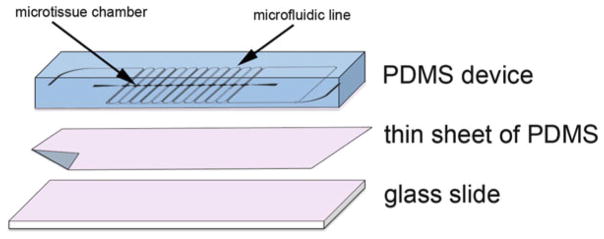
Assembly of microfluidic device for in vitro-perfused human capillaries. Plasma-treated surfaces (indicated in pink color) of PDMS device, sheet of PDMS, and glass slide are bonded together and baked in 120 °C oven for 15 min to obtain PDMS-enclosed chambers
Fig. 2.
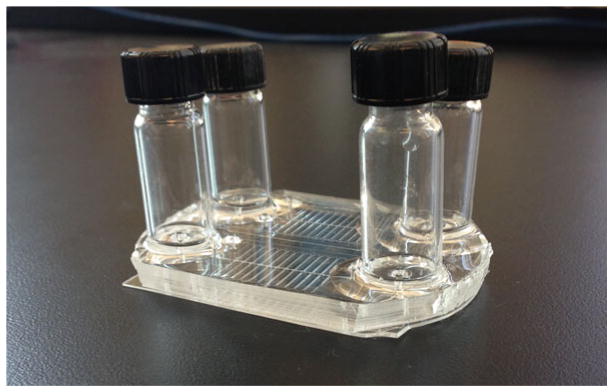
Macroscopic view of assembled microfluidic device with glass vial reservoirs attached to the PDMS chamber bonded to a thin layer of PDMS and a glass slide. Also visible are the microfluidic lines that will contain cell culture media or fibrin and cells
2.3 Cell Preparation
Trypsinize, collect, and count cells needed for experiment.
- Reconstitute cells at desired cell density (see chart), and combine. Cells can then be spun down together. Note that cord blood endothelial colony-forming cell-derived endothelial cells (ECFC-EC) and normal human lung fibroblasts (NHLF) work well for this assay. However, other endothelial cell sources (e.g., human umbilical vein endothelial cells, HUVEC) and stromal cell sources (e.g., dermal fibroblast) have also been successfully substituted (11–13).
Experiment Cell density Vasculogenesis model ECFC-ECs 2.5 × 10⁶ cells/ml NHLFs 5 × 10⁶ cells/ml
Tumor vasculogenesis model SW620s 160,000 cells/ml ECFC-ECs 2.5 × 10⁶ cells/ml NHLFs 5 × 10⁶ cells/ml
2.4 Hydrogel Preparation
Prepare fibrinogen (Sigma) by reconstituting in Dulbecco’s phosphate-buffered saline (DPBS) to a final concentration of 10 mg/ml.
Allow fibrinogen solution to warm, and dissolve by placing in 37°C water bath for a minimum of 15 min.
Once fibrinogen solution is fully dissolved, the solution should then be sterile filtered using a 0.22 μm syringe filter.
3 Methods
3.1 Loading Device
Remove devices from autoclave, and allow to cool at room temperature before proceeding to load with hydrogel and cells.
Resuspend cells in prepared fibrinogen according to desired volume and cell density (see Note 4).
Pipette 30 μl of cell–fibrinogen mixture into a microcentrifuge tube containing 1.8 μl of 50 U/ml thrombin, and mix thoroughly while avoiding the creation of air bubbles (see Note 5).
Using a filtered pipette tip, quickly (<3 min) collect a minimum of 25 μl of mixture and insert into the inlet of the tissue channel applying steady and even pressure to avoid leakage of hydrogel into adjacent fluidic channels. Keep applying a steady pressure until the mixture reaches the outlet of the tissue chamber (Fig. 3) (see Note 6).
Incubate device in 37 °C humidified incubator for a minimum of 30 min and up to 1 h to ensure full fibrin polymerization.
Fig. 3.
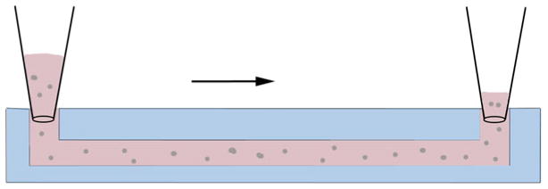
Side-view schematic of loading tissue chambers. Prior to polymerization, the fibrinogen–cell mixture is micropipetted into the inlet of the tissue chamber using steady even pressure
3.2 Introducing Media into Fluidic Lines
Insert 200 μl of fully supplemented EGM-2 (Lonza) into the inlet of one adjacent microfluidic channel applying steady, even pressure until the media reaches the outlet of the microfluidic channel forming a small bubble of media.
For the other microfluidic line, insert into the outlet a small piece of tygon tubing (0.02″ ID × 0.06″ OD) to connect or couple the two microfluidic lines. Repeat previous step with the second channel ensuring that the media enters and forms a small droplet of fluid at the end of the microfluidic line. Alternatively, the microfluidic lines may remain uncoupled, if desired, by not employing the small plastic tubing.
Connect fluid-filled tubing with the outlet of the first channel, and avoid introducing any air gaps (see Note 7).
Once connected, fill reservoirs with media. Set a height difference of 10 mm between the two reservoirs to allow media to follow through the fluidic channels as well as across the tissue chambers. Note that a larger or a smaller height difference can be employed to produce higher or lower flows, respectively, if desired.
Place assembled device into a 20 % O2 incubator overnight.
3.3 Maintenance of Culture Within the Microfluidic Device
The day after seeding the device, replace the media with EGM-2 without VEGF and bFGF. Device can then be moved to a 5 % O2 incubator for the remainder of the study, if desired (see Note 8).
Continue to level the fluid in the reservoir every other day to maintain the 10 mm (or other) height difference.
After 7 days of culture, reverse the direction of the interstitial flow across the tissue chamber by reversing the pressure head in the reservoirs. This encourages vessels to grow towards both pores on either side and form connections with the microfluidic channels.
Footnotes
For easy removal of the PDMS mold from wafer mold, silanize the wafer prior to casting.
If bubbles occur between the layers of PDMS, use a flat-edge surface to press bubbles away from chambers or microfluidic lines. Bubbles in between layers away from chambers or micro-fluidic line are not a problem as they do not interfere with the loading of the device.
Use scotch tape on the surfaces of the device to remove stubborn debris from the PDMS device.
Aliquot cell mixtures in smaller sets for loading to avoid premature polymerization of hydrogel. For example if loading eight samples, split cells into two sets of four loadings.
Fibrinogen–cell mixture will begin polymerizing quickly upon adding thrombin, so perform this step quickly to avoid damaging the gel or creating uneven polymerization.
To avoid introducing bubbles into cell–fibrinogen–thrombin mixture, change tips in between mixing the solution and loading the solution into the device.
When connecting tubing and microfluidic channels make sure to touch the liquid-formed droplet at the microfluidic line outlet to the small droplet formed at the tip of the tubing so as to always maintain fluid–fluid contact and avoid introducing air bubbles.
To minimize evaporation of media from the reservoirs of the device while in the incubator, create a secondary humidity chamber by placing the microfluidic devices into a box with a non-airtight lid containing a reservoir of water of about 20 ml.
References
- 1.Newman AC, Nakatsu MN, Chou W, Gershon PD, Hughes CCW. The requirement for fibroblasts in angiogenesis: fibroblast-derived matrix proteins are essential for endothelial cell lumen formation. Mol Biol Cell. 2011;22 (20):3791–3800. doi: 10.1091/mbc.E11-05-0393. [DOI] [PMC free article] [PubMed] [Google Scholar]
- 2.Montesano R, Pepper MS, Orci L. Paracrine induction of angiogenesis in vitro by Swiss 3T3 fibroblasts. J Cell Sci. 1993;105 (4):1013–1024. doi: 10.1242/jcs.105.4.1013. [DOI] [PubMed] [Google Scholar]
- 3.Moya ML, Hsu YH, Lee AP, Hughes CC, George SC. In vitro perfused human capillary networks. Tissue Eng Part C Methods. 2013;19(9):730–737. doi: 10.1089/ten.TEC.2012.0430. [DOI] [PMC free article] [PubMed] [Google Scholar]
- 4.Vickerman V, Blundo J, Chung S, Kamm R. Design, fabrication and implementation of a novel multi-parameter control microfluidic platform for three-dimensional cell culture and real-time imaging. Lab Chip. 2008;8(9):1468–1477. doi: 10.1039/b802395f. [DOI] [PMC free article] [PubMed] [Google Scholar]
- 5.Hsu YH, Moya ML, Abiri P, Hughes CC, George SC, Lee AP. Full range physiological mass transport control in 3D tissue cultures. Lab Chip. 2013;13(1):81–89. doi: 10.1039/c2lc40787f. [DOI] [PMC free article] [PubMed] [Google Scholar]
- 6.Hsu Y-H, Moya ML, Hughes CCW, George SC, Lee AP. A microfluidic platform for generating large-scale nearly identical human microphysiological vascularized tissue arrays. Lab Chip. 2013;13(15):2990–2998. doi: 10.1039/c3lc50424g. [DOI] [PMC free article] [PubMed] [Google Scholar]
- 7.Kim S, Lee H, Chung M, Jeon NL. Engineering of functional, perfusable 3D microvascular networks on a chip. Lab Chip. 2013;13(8):1489–1500. doi: 10.1039/c3lc41320a. [DOI] [PubMed] [Google Scholar]
- 8.Song JW, Bazou D, Munn LL. Anastomosis of endothelial sprouts forms new vessels in a tissue analogue of angiogenesis. Integr Biol (Camb) 2012;4(8):857–862. doi: 10.1039/c2ib20061a. [DOI] [PMC free article] [PubMed] [Google Scholar]
- 9.Whitesides GM, Stroock AD. Flexible methods for microfluidics. Phys Today. 2001;54 (6):42–48. doi: 10.1063/1.1387591. [DOI] [Google Scholar]
- 10.Duffy DC, McDonald JC, Schueller OJA, Whitesides GM. Rapid prototyping of microfluidic systems in poly(dimethylsiloxane) Anal Chem. 1998;70(23):4974–4984. doi: 10.1021/Ac980656z. [DOI] [PubMed] [Google Scholar]
- 11.Chen X, Aledia AS, Ghajar CM, Griffith CK, Putnam AJ, Hughes CC, George SC. Prevascularization of a fibrin-based tissue construct accelerates the formation of functional anastomosis with host vasculature. Tissue Eng Part A. 2009;15(6):1363–1371. doi: 10.1089/ten.tea.2008.0314. [DOI] [PMC free article] [PubMed] [Google Scholar]
- 12.Ghajar CM, Blevins KS, Hughes CC, George SC, Putnam AJ. Mesenchymal stem cells enhance angiogenesis in mechanically viable prevascularized tissues via early matrix metallo-proteinase upregulation. Tissue Eng. 2006;12 (10):2875–2888. doi: 10.1089/ten.2006.12.2875. [DOI] [PubMed] [Google Scholar]
- 13.Chen XF, Aledia AS, Popson SA, Him L, Hughes CCW, George SC. Rapid Anastomosis of Endothelial Progenitor Cell-Derived Vessels with Host Vasculature Is Promoted by a High Density of Cotransplanted Fibroblasts. Tissue Eng Part A. 2010;16(2):585–594. doi: 10.1089/Ten.Tea.2009.0491. [DOI] [PMC free article] [PubMed] [Google Scholar]