Abstract
Introduction
Recent advances have enabled fast magnetic resonance imaging (MRI) of solid materials. This development has opened up new applications for MRI, but, at the same time, uncovered new challenges. Previously, MRI-invisible materials like the housing of MRI detection coils are now readily depicted and either cause artifacts or lead to a decreased image resolution. In this contribution, we present versatile, multi-nuclear single and dual-tune MRI coils that stand out by (1) a low hydrogen content for high-resolution MRI of dry solids without artifacts; (2) a modular approach with exchangeable inductors of variable volumes to optimally enclose the given object; (3) low cost and low manufacturing effort that is associated with the modular approach; (4) accurate sample placement in the coil outside of the bore, and (5) a wide, single- or dual-tune frequency range that covers several nuclei and enables multinuclear MRI without moving the sample.
Materials and Methods
The inductors of the coils were constructed from self-supporting copper sheets to avoid all plastic materials within or around the resonator. The components that were mounted at a distance from the inductor, including the circuit board, coaxial cable and holder were manufactured from polytetrafluoroethylene.
Results and Conclusion
Residual hydrogen signal was sufficiently well suppressed to allow 1H-MRI of dry solids with a minimum field of view that was smaller than the sensitive volume of the coil. The SNR was found to be comparable but somewhat lower with respect to commercial, proton-rich quadrature coils, and higher with respect to a linearly-polarized commercial coil. The potential of the setup presented was exemplified by 1H / 23Na high-resolution zero echo time (ZTE) MRI of a model solution and a dried human molar at 9.4 T. A full 3D image dataset of the tooth was obtained, rich in contrast and similar to the resolution of standard cone-beam computed tomography.
Introduction
The advent of fast sequences for magnetic resonance imaging (MRI) with echo times (TE) of the order of microseconds has opened up new, previously inaccessible applications that include the imaging of solids and nuclei whose signal decays too fast to be detected otherwise.
In conventional MRI-sequences, the signal of solid-state or otherwise short-lived MR-active nuclei decays during the delay between signal excitation and its detection when the spatial information is encoded. In specialized MR sequences like ultra-short TE (UTE), zero-TE (ZTE) [1,2], sweep imaging with Fourier transformation (SWIFT) [3] and constant-time (CTI) or single-point imaging (SPI) [4,5], this delay can be shortened to a few micro seconds. As a consequence, many of the materials used for the construction of MR coils, patient or animal beds are readily depicted (Fig 1) [6]. This effect is not predominant if wet samples that are rich in signal are investigated, which is true for all in vivo applications. It is a major hindrance, however, if very dry samples are the subject of the examination, e.g. mummies [7–9], teeth [10–15], bone [16] or ceramics. Here, signal sources outside the imaging volume, the field of view (FOV), cause severe artifacts. One way to avoid these artifacts is to include all signal sources by increasing the FOV. Because this volume is typically much larger than the object of interest, the image resolution is reduced or the scan time increased.
Fig 1. MRI of solids.
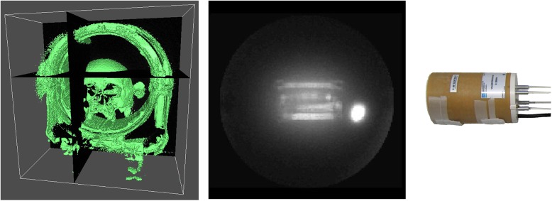
3D rendering of a skull found in a late roman settlement, estimated 300–400 A.D., and head coil acquired with an UTE sequence at 1.5 T (left). 3D maximum intensity projection of a 1H-ZTE image of a quadrature mouse coil at 9.4 T (center, QR2) and corresponding photograph (right).
Another solution is to avoid these signals in the first place by using e.g. hydrogen-poor materials for the construction of coil, bed and support. This approach was discussed before [6,12] and is the subject of this contribution.
Here, we present cost-efficient and very versatile single- and dual-tune transmit-receive coils of modular design with low hydrogen content. These coils offer a high and wide frequency range that allows multinuclear (e.g. 1H, 19F, 17O and 23Na) conventional and UTE/ZTE MRI. In contrast to other implementations, entirely plastic-free, self-supporting copper inductors were developed and used in conjunction with circuit boards with dramatically reduced hydrogen content.
The modular approach enabled a great flexibility with respect to the active volume, resonance frequency and thus nuclei. Conventional MR coils are one fixed and complete assembly that doesn't allow for changing the active volume or frequency. Instead, an entirely new coil is required, whose cost easily exceeds a few €/$ 10.000.
Our approach follows a different path that allows one to choose an appropriate circuit board and an appropriate self-supporting, copper-only inductor to assemble a coil that has the desired frequency and active volume without soldering.
We demonstrate the capability of these coils by acquiring high-resolution 1H and 23Na-ZTE images of model solutions, a dried mucsa domestica and a human tooth at 9.4 T. The low hydrogen content of the entire assembly allowed us to use a FOV that was smaller than the active volume of the coil, which was not feasible with the standard, hydrogen-rich commercial coils.
Materials and Methods
Construction of coils
To achieve a high flexibility and to reduce the associated cost and construction effort, we chose a modular approach to construct the coils, where the inductors and the circuit board (CB) were exchangeably mounted on holders made from polytetrafluroethylene (PTFE).
The complete coil assembly consisted of the inductor, removably connected to a circuit board, and a contraption to hold the assembly. All components were designed to have low hydrogen content.
Inductors
The inductivity and self-capacity of solenoidal coils with the desired inner volume of a few cm3 were found to be 102–103 nH and of the order of 1 pF. These values yield a self-resonance of the desired resonance frequency of the order of 102 MHz (using f = (2 π √(LC)) -1). With a tuning capacitor added, the desired resonance frequencies of 300 and 400 MHz could not be realized.
Loop-gap (LG) resonators of the same inner volume have a much lower inductivity of the order of 101 nH. LG inductors were used for constant-time imaging (CTI) or single-point imaging (SPI) before, but at a lower, single frequency of 200 MHz, incorporated into a proton-poor plastic housing and with a small active volume [6]. Here, we used self-supporting loop-gap resonators that were manufactured in various sizes of copper (Fig 2, Table 1). Still, to reach the desired frequencies, it was necessary to use capacitors in a row to reduce the total capacitance, as shown in Fig 3 (all variable capacitors from Alfred Tronser GmbH, Germany, all fixed value capacitors from SRT Resistor Technology, Cadolzburg, Germany, all inductors from EPCOS AG, Munich, Germany).
Fig 2. Representative photograph of several loop-gap inductors that were constructed (LG1–6). Note the ledges used for connection. Dimensions are provided in Table 2.

Table 1. Quality factor (Q), tunable frequency range (f r) and addressable nuclei at 7 T and 9.4 T for coils composed of a circuit board (CB) and loop-gap (LG) resonator, in comparison to a commercial quadrature resonator (QR2) and linear resonator (LR).
The proprietary connectors of QR1 did not allow a connection to the network analyzer.
| CB | LG | Loading | Q ± SD (f(MHz)) | f r (MHz) | Nuclei |
|---|---|---|---|---|---|
| CB1 | LG2 | No | 234 ± 13 (300) | 114–462.5 | 7Li, 31P, 3He, 19F, 1H |
| Yes | 124 ± 4 (300) | 113.4–461.8 | |||
| LG4 | No | 89 ± 2 (300) | 104.1–392.2 | ||
| Yes | 82 ± 2 (300) | 104.1–391.9 | |||
| LG6 | No | 176 ± 7 (300) | 103.6–383.8 | ||
| Yes | 169 ± 7 (300) | 103.6–383.6 | |||
| CB2 | LG2 | No | 219 ± 9 (400) | 365.6–666.3 | 1H, 19F |
| Yes | 193 ± 7 (400) | 364.9–660.6 | |||
| CB3 Port 1 | LG4 | No | 47.7 ± 0.8 (105.8) | 88.3–131.7 | 7Li,31P, 23Na, 13C, 1H, 19F |
| Yes | 48.3 ± 0.8 (105.8) | 88.3–131.7 | |||
| CB3 Port 2 | LG4 | No | 46.5 ± 0.4 (400) | 332.8–564.2 | |
| Yes | 46.5 ± 0.4 (400) | 332–564.2 | |||
| QR2 | No | 445 ± 35 (400) | 392.6–416.8 | 1H | |
| QR2 | Yes | 400 ± 30 (400) | 392.5–416.4 | ||
| LR | No | 42.5 ± 0.3 (400) | 378.4–403.7 | ||
| LR | Yes | 42.5 ± 0.3 (400) | 378.4–403.6 |
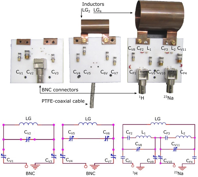
Fig 3. Photographs and schematics of the single-tune circuit boards (CB1, left and CB2, center) and dual-tune circuit board (CB3, right) with and without loop-gap (LG) inductors.
Conventional BNC connectors (left and right) as well as a custom-made PTFE coaxial cable with low hydrogen content are shown (center). Values of variable capacitors are: CV1,3-9 = 0.3–3.5 pF, CV2,10,11 = 1.1–16 pF; fixed-value capacitors: CF1 = 1 pF, CF2 = 100 pF, CF3 = 6.8 pF, CF1 = 10 pF; inductors: L1,2 = 22 nH.
To facilitate the combination of various inductors of different sizes with several circuit boards without soldering, ledges were added to the loop-gap cylinders. These ledges were connected to matching copper terminals on the circuit boards using copper screws.
The construction of the inductors was facilitated by cutting thin copper sheets of 0.5 mm thickness to the required shape before preparing the ledges and bending the cylinders. Several inductors were constructed, some are shown (LG1 –LG6) and three were characterized in detail (LG2, LG4, LG6).
Circuit board
The circuit boards (CB) were cut from a slab of polytetrafluorethylene (PTFE) to slices of ≈ 2 mm thickness (Table 1. Variable and fixed capacitors were mounted on holes drilled through the PTFE board and connected with silver-plated wire following the scheme in Fig 3. A BNC connector (TE Connectivity, Greenpar, Germany) was mounted at a distance of ≈ 3 cm from the 5∙5∙2 mm copper terminals that held the inductors. The dual-tune circuit board (CB3) was equipped with two input/output ports.
A PTFE coaxial cable was soldered to the circuit board to replace the BNC jack and coaxial cable. The PTFE cable was constructed by removing the outer insulation layer of a non-magnetic coaxial RG58 cable, and replacing the insulation layer between outer and inner conductor by PTFE tubing with 4 mm outer and 2 mm inner diameter (FA. Bürkert, Germany).
For each assembly, the addressable frequency range was measured using a network analyzer in S11 mode (E5061B, Agilent Technologies, USA). Likewise, the Q-factor was determined with and without 5 ml of an aqueous model solution that contained 0.9% NaCl (phantom P1) by dividing the resonance frequency by the half width at half minimum of the S11-attenuation curve (Table 2).
Table 2. Dimensions of exchangeable loop-gap (LG) inductors that were mounted on the circuit boards (CB) and sensitive volume of the commercial quadrature birdcage resonators (QR1 and QR2) and linearly-polarized birdcage resonator (LR).
| Object | Length (mm) | Diameter or width (mm) | Ledge length (mm) | Ledge width (mm) |
|---|---|---|---|---|
| LG1 | 40 | 15 | 15 | 10 |
| LG2 | 40 | 20 | 15 | 11 |
| LG3 | 40 | 36 | 15 | 10 |
| LG4 | 60 | 42 | 20 | 15 |
| LG5 | 40 | 52 | 15 | 15 |
| LG6 | 60 | 51 | 16 | 20 |
| CB1 | 6.6 | 7.9 | - | - |
| CB2 | 7.0 | 7.5 | - | - |
| CB3 | 6.5 | 8.2 | - | - |
| QR1 (7 T) | 60 | 42 | - | - |
| QR2 (9.4 T) | 59 | 37 | - | - |
| LR (7 T) | 112 | 74 | - | - |
Holder
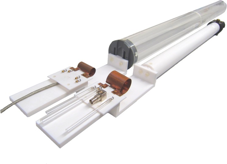
A holder was manufactured from PTFE to mount the circuit board and inductors of various sizes. It was adapted to match the available animal beds of the MRI systems. The setup enabled precise placement of the samples within the center of the coil outside the bore instead of tedious placement of the sample within the bore-mounted standard coils.
MRI, CBCT and phantoms
A 7 T and 9.4 T small-bore MR imaging system was used (Biospec 7/20 and 9.4/20, respectively, ParaVision 5.1, Bruker, Germany) in conjunction with the presented coils and a quadrature birdcage mouse coil for 7 T (QR1, Rapid Biomed, Würzburg, Germany), a quadrature birdcage mouse coil for 9.4 T (QR2, Bruker) as well as a linearly-polarized birdcage rat coil for 9.4 T (LR, Bruker). Product FLASH- as well as ZTE-sequences were applied with parameters indicated where appropriate.
The coils were mounted on the MR system (Fig 4), loaded with a phantom and introduced to the bore, where they were tuned to the resonance frequency and matched to the impedance of the MR system. The manufacturer’s standard procedure to adjust transmitter frequency, flip angle, receiver gain and B 0 homogeneity were applied, using a slice orthogonal to the phantom axis (Table 3). The calibration of the flip angle is expressed as the power that is required for a 90° block pulse of 1 ms length. Note that the cylindrical active volume of the commercial coils was in parallel to the magnetic field B 0 and the LG resonators were perpendicular.
Fig 4. Photograph of the complete coil assemblies, CB1 with LG4 (front) and CB2 with LG2 (back), ready to be mounted to the bores of the 7 T and 9.4 T MR systems.
Table 3. Signal, noise, signal-to-noise-ratio (SNR) and reference pulse power (P W 90) of a 1 ms, 90°-pulse for the coils composed of a circuit board (CB) and loop-gap (LG) inductor, as well as for commercial coils that were polarized in quadrature (QR1, QR2) and linear (LR).
| Coil | f (MHz) | Signal (106) | Noise (104) | SNR | P W 90 (W) |
|---|---|---|---|---|---|
| CB1 + LG2 | 300 | 1.11 | 1.03 | 107.8 | 1.13 |
| CB2 + LG2 | 400 | 2.06 | 1.27 | 162.2 | 0.411 |
| CB2 + LG1 | 400 | 5.14 | 1.5 | 342.7 | 0.103 |
| QR1 | 300 | 1.85 | 0.68 | 271.7 | 0.143 |
| QR2 | 400 | 5.9 | 1.05 | 561.9 | 0.530 |
| LR | 400 | 0.94 | 0.95 | 98.4 | 4.72 |
The manufacture’s specifications for maximum peak (5 ms) and mean power for QR1 were 200 W and 1.9 W, 400 W and 4 W for QR2, and 750 W and 22 W for LR, respectively.
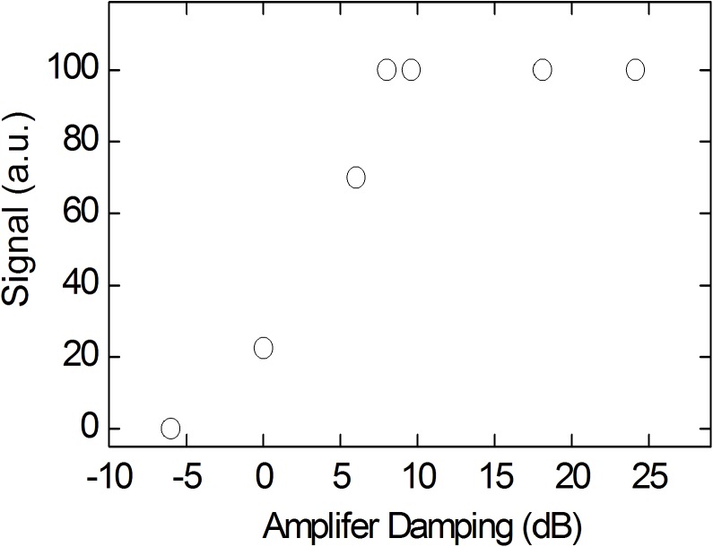
To determine the maximum pulse power applicable to the constructed coils, non-localized 1H or 23Na spectra were acquired with a constant flip angle and variable pulse power P W and pulse length. For example, the signal was found to decrease for a single-tune 1H coil that was composed of CB2 and LG1 at 9.4 T for a pulse power exceeding Pw = 22 W (Fig 5), and for the 23Na-channel of the dual tune coil at 7 T at a pulse power exceeding 170 W.
Fig 5. 1H-MR signal height of a tooth acquired with unlocalized spectroscopy as a function of pulse power using a constant flip angle (α ≈ 6°) at 9.4 T with CB2 and LG1.
Note that the MR signal decreased for powers exceeding 22 W.
The transmitter power P W in Watt was obtained by converting the attenuation setting A dB in dB using the manufacturer's calibration of the amplifier's maximum output at 50 Ωnamely 542 W for the 300 MHz 1H-channel at 9.4 T, and 835 W for the X-nuclei channel at 23Na-frequency of 105.8 MHz at 7 T (A dB = -6 dB–10 ∙ log10(P W/542 W) dB).
The images were reconstructed using the manufacturer’s software and prepared for publication using open-source software (ImageJ [17], MIPAV [18], inkscape and GIMP (www.gimp.org). The signal-to-noise ratio (SNR) was obtained by dividing the mean signal of a region of interest (ROI) by the standard deviation of the noise from an apparently signal-free region of the image. The values were obtained using the manufacturer’s software (Paravision 5.1, Bruker).
The background signal of the constructed coils was investigated by applying a ZTE sequence to an empty coil at 9.4 T (TR = 4 ms, a = 3.3°, 100 kHz bandwidth, 8 cm FOV, 1283 matrix).
To compare the SNR among the coils, a FLASH sequence was used in conjunction with phantom P1 (TE = 6 ms, TR = 100 ms, α = 30°, 128 matrix, 6 cm FOV, 2 mm slice thickness; phantom P1: 5 ml solution of 0.9% NaCl in an Eppendorf tube).
To demonstrate MRI of dry samples and the associated artefacts, a dried musca domestica was examined with ZTE MRI at 7 T using CB1 and LG2 in comparison to QR1 (TR = 1 ms, α = 2°, FOV = (3 cm)3, matrix 64).
At 9.4 T, an extracted human molar was dried for a few hours before it was imaged with ZTE MRI using CB2 and LG1 (TR = 4 ms, α = 5.6°, BW = 200 kHz, FOV = 2.5 cm, Matrix 128, voxel size = 195 μm, 6 μs pulse at 10.8 W, N = 80, t acq = 4.37 h). For comparison, a CBCT of the tooth was acquired afterwards (FOV 14.5 cm, nominal resolution 250 μm, 85 kV, 300 images, Scanora 3D, Soredex, USA). Informed consent was obtained from the donor for use in this study.
Multinuclear ZTE MRI of 1H- and 23Na nuclei was demonstrated without moving the setup using CB3 and LG4 in conjunction with a model solution of deionized water with 100 g NaCl / l (phantom P2, ≈ 12 ml, sequence parameters for 1H / 23Na: TR = 1 / 4 ms, α = 0.9°/4.5°, bandwidth 200 / 100 kHz, voxel size 0.78 / 1.56 mm, averages 1 / 2).
Results
ZTE MRI and background signal
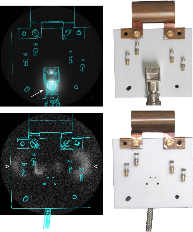
All presented coils successfully enabled MRI at 7 T or 9.4 T, respectively. Interestingly, unwanted signal from the BNC jack and the connected coaxial cable was readily depicted on large-FOV ZTE images of the empty coil, despite the fact that both components were at ≈ 4 cm distance and thus well outside the inductor itself, as indicated in Fig 6, top, by the arrow. The signal vanished when the custom-made, hydrogen-poor coaxial cable was used instead as shown on the bottom of Fig 6. Instead, a new signal that originated from the approximate positions of the variable capacitors was observed, indicated by wedges.
Fig 6. 3D maximum-intensity-projection ZTE MRI and approximate coil positions (left) acquired at 9.4 T and photograph of coil assembled from CB2 and LG2 (right), either with a conventional BNC connector and coaxial cable (top), or a custom-made PTFE cable that was soldered to the circuit board (bottom).
Note that the signal originating from the BNC connector was removed using the custom build cable. In turn, signal originating from the variable capacitors appeared close to the noise level (FOV = 20 cm).
As it turned out, this signal was not sufficiently large to yield strong artifacts when the FOV was reduced to a volume within the inductor (Fig 7A). A musca domestica was depicted in one low-resolution ZTE acquisition with a SNR of 14, and only a thin, one-to-two-voxel artifact rim was visible at the edge of the FOV with a SNR of 7.5 (standard deviation (SD) of noise: 317 a.u.). In contrast, strong artifacts were observed across the entire FOV when QR1 was used with the same parameters (Fig 7B). Here, the diffuse distribution of the artifact exacerbated the accurate determination of the noise to calculate the SNR. Note that the artifact signal contributed to the region of noise and musca. With respect to the noise in a region where the artifact was less pronounced (SD = 1320 a.u.), the SNR was 27 for the mucsa domestica and 19 for the maximum artifact.
Fig 7. 1H-ZTE images of a dried musca domestica acquired ex vivo with a commercial quadrature coil (left, QR1) and new, hydrogen-poor coil composed of CB1 and LG2 (right) with identical settings at 7 T.
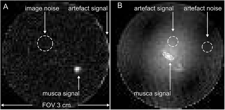
Note that the strong artifacts on the left were induced by signal sources from outside of the FOV that was (3 cm)3. In contrast, these artifacts did not appear when the modular loop-gap coil was used (right).
Note that the dried mucsa domesitca served as phantom with very low signal intensity only.
Whereas Horch et al. [6] reported MRI of ambient air moisture using a CTI sequence, we did not observe an increased signal from within the inductor.
SNR and calibrations
The power required to apply a 1 ms, 90°-reference pulse with the presented coils was similar to the power required by the quadrature coils QR1,2, and less for the large linear coil LR (Table 3, e.g. 0.43 W for CB2 + LG2 and 0.54 W for QR2 at 9.4 T).
The SNR of the constructed coils was found to be of the same order of magnitude but lower with respect to the quadrature coils QR1,2, and higher with respect to the linear coil LR. This finding appears to be in contradiction to the principle of reciprocity but may, at least partially, be attributed to a higher noise figure of the LG coils. In contrast to the quadrature coils, the constructed coils weren't equipped with an outer r.f. shield.
1H and X-nuclei ZTE MRI
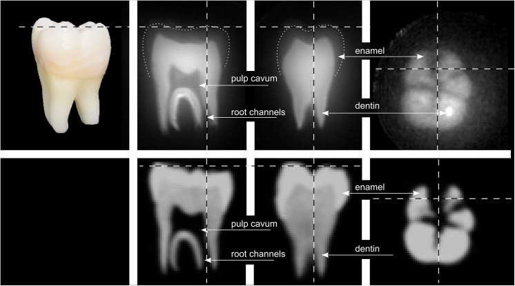
To exemplify the coils performance, an extracted human molar was subjected to ZTE MRI at 9.4 T using CB2 and LG1 (Fig 8). The FOV was set to (2.5 cm)3, the smallest volume covering the entire sample and well within the inductor. The shortest 1H-pulse feasible was 6 μs at 11.1 W, resulting in a ≈ 5.4° flip angle as calculated by the automatic calibration routine. At a matrix size of 128, an isotropic voxel size of (195 μm)3 was obtained and 80 averages were acquired (TR = 4 ms).
Fig 8. Photograph (top left), orthogonal reconstructions of a 3D ZTE MRI of an extracted human molar acquired at 9.4 T with CB2 and LG1 (top row) and 3D CBCT (bottom row).
Note that the brightness of the MRI on the right was adjusted to show the enamel. Dashed lines indicate the slice positions, dotted lines the approximate outline of the enamel.
The pulpa cavum, dentin and, with the appropriate windowing, enamel were readily depicted. Before, a coil cooled to crygenic temperatures or much longer scan times were required to show enamel [12,13].
Compared to CBCT with a nominal resolution of 250 μm, the ZTE MRI appears sharper and richer in contrast, with the exception of enamel, which is much better depicted by CBCT.
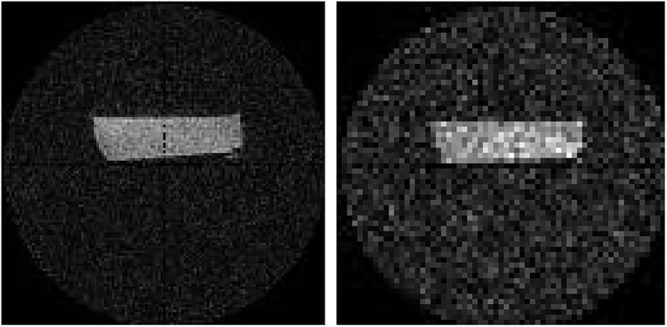
To demonstrate the feasibility of multinuclear MRI, three-dimensional 23Na- and 1H-ZTE MRI of an aqueous NaCl solution was performed consecutively using the dual-tune coil (CB3, LG4) without moving sample. Both nuclei were readily depicted (Fig 9).
Fig 9. 1H- and 23Na-ZTE MRI of an aqueous model solution containing 100 g NaCl / l acquired with LG4 and CB3 at 9.4 T.
Discussion
Feasibility of multinuclear ZTE MRI
The hydrogen-poor transmit-receive coils with exchangeable inductors that were presented here are distinguished by the absence of all plastic materials in the vicinity of the inductor, the modular approach that allows an optimal filling factor and multinuclear applicability.
The coils are low in cost and relatively easy to manufacture, but, at the same time, provide satisfactory performance. Not surprisingly, inductors with a loop-gap geometry were successfully used for MRI of solids before [6]. However, the conceptual design presented here as well as the frequency, components and the sequences used are different.
All plastic materials near to the inductor were avoided by using a self-supporting copper inductor that was exchangeably mounted at a distance of one centimeter on a PTFE board. Other proton-rich materials including the insulation of a coaxial cable and a BNC terminal were removed. In the final setup, only the variable capacitors yielded ZTE signal, despite the fact that they were mounted outside of the inductor at a distance of several centimeters. Whereas the residual signal was too weak to cause interfering artifacts, it may be avoided in the future by using capacitors made from proton-poor materials only.
High resolution sodium and hydrogen images were acquired at 9.4 T to demonstrate the feasibility of ZTE MRI with the presented coils. It was the first time, to our knowledge, that dental enamel was depicted with a ZTE sequence using a coil at room-temperature. When the same sample was imaged using a conventional quadrature coil, strong artifacts arose that originated from the proton-rich components of the coil outside of the FOV.
Geometry
Loop-gap resonators provide a small inductivity, a good B 1 homogeneity but, given the geometry, no easy access to the inner coil volume when mounted in the magnet's bore.
This challenge was overcome in the current implementation by moving the entire coil assembly, mounted on the animal bed, in- and out of the magnet. In fact, this scheme proved to be beneficial when it came to placing a small sample accurately in the center of the coil. If sample placement outside of the bore is not an option, a simple saddle-shaped inductor that is connected to the presented circuit boards may constitute a viable alternative. It is expected, though, that the inductivity of a saddle-shaped inductor is higher than a comparable loop-gap resonator and that it will thus affect the resonance frequency.
SNR
Both reference pulse power as well as SNR was similar or of the same order of magnitude for the commercial quadrature coils and constructed loop-gap resonators, respectively.
The differences in SNR that were found are not unexpected because of different geometries, materials and linear / quadrature polarization that is expected to yield √2 more SNR.
It appears though, that the somewhat lower SNR of the LG coils may be attributed to a higher noise, which may be attributed to relatively low-priced variable capacitors and the absence of a r.f. shield as was included in the commercial coils.
Cost, flexibility and ease of use
The complete materials for one single-tune coil assembly with several inductors do not exceed €/$ 50, which is several orders of magnitude less than the cost of a commercial coil. However, as pointed out above, a higher SNR may be achieved with capacitors of higher quality that are more expensive and appropriate shielding. The matching and tuning of the coils in the bore of the magnet could be facilitated by long rods permanently connected to the capacitors, and a smaller range of the variable capacitors.
The wide tuning range of the capacitors enabled to image several nuclei with one setup, which greatly facilitates proof-of-principle X-nuclei experiments without the need of acquiring a dedicated coil whose cost easily exceed €/$ 10.000. The modular approach of using interchangeable inductors and circuit boards has proven to add significantly to the applicability and flexibility of the presented coils.
Conclusion
Single and dual-tune coils for conventional MRI as well as close-to-zero echo-time MRI of 1H and X-nuclei at 7 T and 9.4 T were presented. Background signal was significantly reduced by constructing the coils from materials with very low hydrogen content using self-supporting plastic-free inductors and a coaxial cable with low hydrogen content. A modular approach enabled the combination of inductors of various sizes with one circuit board to assure an optimal filling factor, a wide range of addressable nuclei and a reduction of the overall cost to ≈50$. These properties enabled high-resolution ZTE MRI of solids with a FOV within the inductor as exemplified by imaging an extracted human tooth including its enamel.
Acknowledgments
We are grateful for the support and helpful discussions with Waldemar Schimpf, Frank Hüthe, Gerd Strohmeier, Thomas Günter and Jochen Leupold. JBH wishes to acknowledge support by the DFG, HO 4604/2-1.
Data Availability
All relevant data are within the paper.
Funding Statement
The authors have no support or funding to report.
References
- 1. Weiger M, Pruessmann KP. MRI with Zero Echo Time. eMagRes. 2012;1: 311–322. 10.1002/9780470034590.emrstm1292 [DOI] [Google Scholar]
- 2. Weiger M, Pruessmann KP, Hennel F. MRI with zero echo time: hard versus sweep pulse excitation. Magn Reson Med. 2011;66: 379–89. 10.1002/mrm.22799 [DOI] [PubMed] [Google Scholar]
- 3. Garwood M, Idiyatullin D, Corum CA, Chamberlain R, Moeller S, Kobayashi N, et al. Capturing Signals from Fast-relaxing Spins with Frequency-Swept MRI: SWIFT. eMagRes. 2012;1 10.1002/9780470034590.emrstm1259 [DOI] [Google Scholar]
- 4. Emid S, Creyghton JHN. High resolution NMR imaging in solids. Physica B+C. 1985;128: 81–83. 10.1016/0378-4363(85)90087-7 [DOI] [Google Scholar]
- 5. Gravina S, Cory DG. Sensitivity and Resolution of Constant-Time Imaging. Journal of Magnetic Resonance, Series B. 1994;104: 53–61. 10.1006/jmrb.1994.1052 [DOI] [Google Scholar]
- 6. Horch RA, Wilkens K, Gochberg DF, Does MD. RF coil considerations for short-T2 MRI. Magn Reson Med. 2010;64: 1652–1657. 10.1002/mrm.22558 [DOI] [PMC free article] [PubMed] [Google Scholar]
- 7.Ludwig U, Hövener J-B, Özen A, Öhrström L, Bitzer A, Walther M, et al. ZTE MRI enables imaging of egypitan mummy: a comparision to CT and THz imaging. Proceedings of the Joint Annual Meeting of ISMRM-ESMRMB. Milan, Italy; 2014.
- 8. Rühli FJ, von Waldburg H, Nielles-Vallespin S, Böni T, Speier P. Clinical magnetic resonance imaging of ancient dry human mummies without rehydration. JAMA. 2007;298: 2618–2620. 10.1001/jama.298.22.2618-b [DOI] [PubMed] [Google Scholar]
- 9. Shin DH, Lee IS, Kim MJ, Oh CS, Park JB, Bok GD, et al. Magnetic resonance imaging performed on a hydrated mummy of medieval Korea. J Anat. 2010;216: 329–334. 10.1111/j.1469-7580.2009.01185.x [DOI] [PMC free article] [PubMed] [Google Scholar]
- 10. Weiger M, Pruessmann KP, Bracher AK, Köhler S, Lehmann V, Wolfram U, et al. High-Resolution ZTE Imaging of Human Teeth. Proc Intl Soc Mag Reson Med 19 Montreal, Canada; 2011. p. 2612. [DOI] [PubMed] [Google Scholar]
- 11. Weiger M, Pruessmann KP, Bracher AK, Köhler S, Lehmann K, Wolfram U, et al. High-resolution ZTE imaging of human teeth. NMR Biomed. 2012; [DOI] [PubMed] [Google Scholar]
- 12. Hövener J-B, Zwick S, Leupold J, Eisenbeiβ A-K, Scheifele C, Schellenberger F, et al. Dental MRI: Imaging of soft and solid components without ionizing radiation. J Magn Reson Imag. 2012;36: 841–846. 10.1002/jmri.23712 [DOI] [PubMed] [Google Scholar]
- 13.Zwick S, Hövener J-B, Leupold J, Schellenberger F, Elverfeldt D von. Towards dental MRI: Zero TE imaging of compromised horse teeth. Proceedings of the 19th Annual Meeting of ISMRM. Montreal, Canada; 2011.
- 14. Idiyatullin D, Corum CA, Nixdorf DR, Garwood M. Intraoral approach for imaging teeth using the transverse B1 field components of an occlusally oriented loop coil. Magnetic Resonance in Medicine. 2013; n/a–n/a. 10.1002/mrm.24893 [DOI] [PMC free article] [PubMed] [Google Scholar]
- 15. Bracher A-K, Hofmann C, Bornstedt A, Hell E, Janke F, Ulrici J, et al. Ultrashort echo time (UTE) MRI for the assessment of caries lesions. Dentomaxillofacial Radiology. 2013;42: 20120321 10.1259/dmfr.20120321 [DOI] [PMC free article] [PubMed] [Google Scholar]
- 16. Weiger M, Stampanoni M, Pruessmann KP. Direct depiction of bone microstructure using MRI with zero echo time. Bone. 2013;54: 44–47. 10.1016/j.bone.2013.01.027 [DOI] [PubMed] [Google Scholar]
- 17. Abramoff MD, Magalhaes PJ, Ram SJ. Image Processing with ImageJ. Biophotonics International. 2004;11: 36–42. [Google Scholar]
- 18.McAuliffe MJ, Lalonde FM, McGarry D, Gandler W, Csaky K, Trus BL. Medical Image Processing, Analysis and Visualization in clinical research. 14th IEEE Symposium on Computer-Based Medical Systems, 2001 CBMS 2001 Proceedings. 2001. pp. 381–386. 10.1109/CBMS.2001.941749 [DOI]
Associated Data
This section collects any data citations, data availability statements, or supplementary materials included in this article.
Data Availability Statement
All relevant data are within the paper.


