Abstract
We describe an instrumented biopsy needle that provides physicians the capability to sense interaction forces directly at the tip of the needle’s inner stylet. The sensors consist of optical fiber Bragg gratings (FBGs), and are unaffected by electromagnetic fields; hence the needle is suitable for MR-guided procedures. In comparison to previous instrumented needles that measure bending strains, the new design has additional sensors and a series of micro-machined holes at the tip. The holes increase strain sensitivity, especially to axial forces, without significantly reducing the stiffness or strength. A comparison of the dynamic forces measured with the new needle and those obtained using a force/torque sensor at the needle base shows that the enhanced tip sensitivity is particularly noticeable when there is significant friction along the needle sleeve.
1 Introduction
Image-guided interventions are becoming increasingly popular as costs decrease and imaging contrast and accuracy improve [18]. In such procedures, direct manipulation of interventional tools such as biopsy needles is attractive to physicians as they can feel the interactions between the tool and tissues, for example while piercing a membrane or coming into contact with a tumor. However, for tools such as biopsy needles, the sensitivity to forces at the needle tip is partially masked by interactions between the needle sheath and the tissue that surrounds it. The needle described in this paper is a direct consequence of a reported wish on the part of some interventional radiologists to virtually “shrink their fingertips” and transport them to the needle tip.
For interventions performed under magnetic resonance imagining (MRI), tactile sensitivity is even more elusive. A difficulty with performing interventions under live MRI is that the patient is confined within a narrow machine bore, which greatly restricts the physician’s access. To address this problem, various MRI-compatible robots and positioning devices have been developed [30, 31, 19, 12]. While these robotic devices include sensors for monitoring their own states, they generally do not provide tactile feedback for the physician. The needle presented here includes fully MR-compatible sensing technology that, when used either in direct manipulation or with a teleoperated robotic device, provides information about forces at the tool tip. This force information can then be displayed to a physician audibly, visually and/or via a haptic feedback device.
In the following sections we first review relevant prior technology and then present the new design, focusing on the measures taken to enhance tip sensitivity. The results of finite element analysis (FEA) are compared with calibration tests to show the force sensitivity of the needle, especially to small axial forces that are most challenging to measure. To illustrate the difference between tip force sensing and force sensing at the needle base, tests were conducted with a 6-axis load cell built into a handle at the needle base. The results of these tests show that the tip sensors are able to ascertain more fine variations in dynamic forces as the needle pushes through a membrane or touches a hard surface through a frictional medium. We conclude with a discussion of future tests involving the haptic display of sensed forces.
2 Background and Related Work
In minimally invasive surgery, interactions between the surgical tool and tissues provide information to the physician. Relying purely on visual cues for estimating interaction forces has been shown to saturate cognitive load [7]. Numerous investigations in robot-assisted minimally invasive surgery, have recognized the need for tactile feedback [29, 23, 24, 8, 25, 32].
However, despite the recognized importance of haptic sensations, progress in creating instrumented minimally invasive tools has been slow due to the technical challenges associated with creating tools with sensors that are robust, sterilizable, biocompatible and reasonably economical. These challenges are particularly severe when the tools must also be MR-compatible.
For general tele-operated surgery, [3] demonstrates a solution in which small accelerometers are mounted on the slave end of a robot-assisted surgical system, producing signals that can be transmitted through a vibrational haptic display at the master. They show that the vibrations associated with events like tool/tool contact and grasping are clearly detectable.
When slender tools such as needles are used in oncological interventions, tool/tissue interactions can produce significant bending [1, 5] in addition to providing haptic information. These tool deflections complicate procedures such as MR-guided biopsy, cryoablation and brachytherapy seed placement. Needle insertion in tissue takes place in three stages [28]. First, the needle makes contact with and deforms the tissue surface. Next, the needle cuts into the tissue and frictional forces pull the skin along the needle shaft. In the third phase, the needle is extracted from the tissue, which again follows the needle’s direction of motion. Often the tissue “puckers” around the needle tip before complete extraction. These stages have distinct force profiles [2]. Several researchers have analyzed these needle interactions during insertions, penetration, and withdrawal [10, 26], while others have demonstrated online estimation of needle interaction forces intraoperatively [2].
When a needle consists of an inner stylet and a surrounding sheath, the measurement of tip forces is complicated by frictional forces along the sheath. [33] outfitted a needle with two axial force cells at its base, one connected to the stylet and the other to the sheath. They observed that at the instant of puncture on a tissue surface, the force output from the sheath increased while that of the stylet decreased. [9] expanded on a similar co-axial needle setup to monitor membrane puncture forces as measured by the cutting force on the stylet versus frictional force on the sheath. They report a higher success rate of user identification of membrane puncture when relying on cutting forces over cutting plus frictional forces.
The needle presented here builds upon a previously developed shape-sensing needle that utilizes optical fiber Bragg grating (FBG) sensors [27]. Optical fibers with Bragg gratings are an attractive solution due to the ability to measure optical wavelength shifts corresponding to very small strains and due to their immunity to electromagnetic fields. Other advantages include physical robustness, small size and the ability to perform optical multiplexing so that strain data can be obtained from multiple FBGs along a single fiber, at rates higher than 1MHz. However, because FBGs are sensitive to temperature, it is important to provide temperature compensation. Medical applications have incorporated FBGs on biopsy needles, catheters and other minimally invasive tools for shape detection and force sensing [22, 21, 27, 16, 34, 16].
3 Tip Force Sensing Needle Design
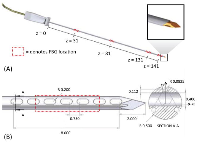
We embedded FBG sensors in a modified off-the-shelf MRI-compatible 18 gage MP35N alloy biopsy needle stylet.1 As in [27], three optical fibers are placed in grooves, located 120 deg. apart on the surface. The fibers in the present case are 125 μm in diameter, allowing for shallower grooves than in the previous design. Triplets of FBGs are located at four locations along the needle, as shown in figure 1. The first three triplets of FBGs are used to measure bending, following the approach presented in [27]. As in the previous work, it is assumed that the needle can be modeled as a slender cantilever beam, with negligible torsion about the major axis because the stylet is encased in an outer sheath. The distal set of FBGs is used for measuring forces at the tip, where bending moments and strains are comparatively small.
Figure 1.
(A) CAD rendering of needle prototype and sensor locations. (B) Detail of tip force sensing features and modified cross-section. All dimensions in mm.
3.1 Mechanical and thermal effects on wavelength
Both the fiber effective refractive index, neff, and the grating period, Λ, vary with changes in strain, ε, and temperature, ΔT. The center Bragg wavelength λB is
| (1) |
For FBG sensors made of isotropic materials, the wavelength shift due to mechanical and thermal strains is
| (2) |
where Pe is the equivalent photoelastic coefficient, εz is axial strain, ζ is the thermo-optic coefficient of the FBG and α is the thermal coefficient of expansion of the material to which the FBG is bonded. For an FBG centered around 1550 nm, typical values are neff = 1.51, Pe = 0.22, α = 0.55e-6/°C, and ζ = 10 pm/°C for silica fiber [4, 14]. With the appropriate optical interrogator, very small strains, on the order of 0.1 μ strain, can be measured at speeds in the kHz range. In the experiments described, we used a Mini-ISense 4800. 1 In practice, the resolution available for strain sensing will generally be somewhat less due to imperfect thermal compensation and calibration.
The actual wavelength changes due to strain and temperature depend on the substrate and configuration in which the FBGs are adhered. The wavelength shift due to strain and temperature is often simplified as:
| (3) |
where Kε and KT are constants representing the sensitivity to mechanical strains and temperature variations, respectively.
3.2 Sensitivity to radial and axial loads
As prior work [27, 16] reveals, it is quite possible to measure the bending strains that result from forces applied to a long slender needle, especially if the gages are located some distance from the needle tip. However it is harder to measure axial forces. To illustrate, consider a needle with an FBG positioned at the midpoint (l/2) of a needle’s length. Modeling the needle as a cantilever beam, if a tip force of magnitude fr is radially applied (normal to the needle’s neutral axis), the strain at the FBG is
| (4) |
where M is the moment produced by fr, c is the radial distance from the neutral axis of the needle to the FBG center (slightly less than r in the maximum case), I is the area moment of inertia and E is the Young’s modulus of the beam material. However, if the tip load is applied axially, the strain is
| (5) |
For the case that fr = fz, with needle dimensions r = 0.5 mm and l = 150 mm, the ratio of strains is εa/εb = 1/600. In addition, there is a problem that axial and thermal strains produce exactly the same effects on a cylindrical beam with a symmetric arrangement of sensors. A solution to overcome this coupling issue is to locate additional FBG sensors near the needle tip, and to modify the tip geometry, making it asymmetric and increasing the strains resulting from axial forces.
3.3 Needle Geometry and Analysis
A new tip geometry was developed to increase the sensitivity of the needle to tip forces. In addition to the three axial channels in which optical fibers are placed, the stylet has a series of oval holes created through electric discharge machining. After analyzing several manufacturable designs with varying numbers of holes of various dimensions, the design in figure 1 was chosen to provide a useful increase in strains resulting from axial loads without significantly decreasing the stiffness and strength of the needle.
The final design includes seven holes, 0.5 mm long with 0.2 mm radius semi-circular edges, spaced 0.75 mm apart. The total length of the modified region is 8.4 mm. In cross section, the holes are positioned between the upper groove position (as seen in Section A-A of figure 1(B)) and the other two grooves.
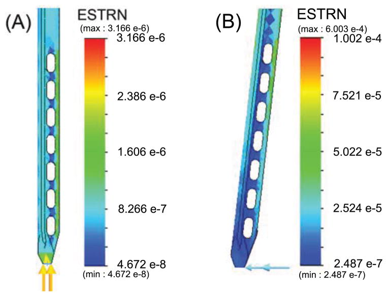
A finite element analysis (linear elastic isotropic model, solid mesh, static analysis, iterative solver) shows how strains are affected by axial and radial loading. For purposes of the FEA, the needle was “blunted” to more realistically apply forces to nodes at the tip. Figures 2 and 3 show the FEA results for strain under 0.1N axial and radial loads. As can be seen, the distal FBGs also experience somewhat increased strains due to radial forces. However, the main difference with respect to a needle without holes is in the axial response.
Figure 2.
FEA results for von Mises strain on the needle under (A) 0.1N axial and (B) 0.1N radial tip loads.
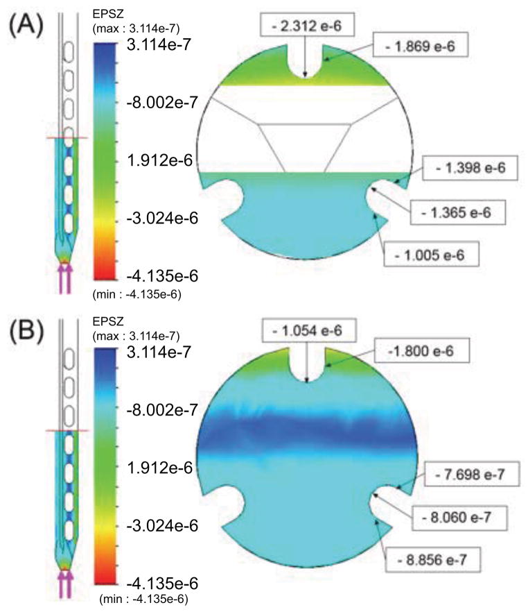
Figure 3.
Axial strains produced by 0.1N axial force at (A) a location centered over one of the oval holes near the middle of the modified region and (B) in a solid part of the cross section.
The comparative strains for the grooved needle with and without holes, measured along the top groove over a 1.5mm length at the center of the FBG, are summarized in Table 1. As expected, the top FBG is more sensitive to loads in the y direction than in the x direction. For a purely axial force, the increase in strain compared to a needle without holes is approximately 300%. The sensitivity to axial loads is still less than for radial forces in the y direction (by a factor of approximately 1/17) but is much improved over the 1/600 sensitivity ratio at the middle of a tool, as noted in Section 3.2.
Table 1.
Average axial strains at upper FBG location
| Load Applied at Tip | εavg, needle with holes | εavg, plain needle | ratio (modified:plain) |
|---|---|---|---|
| Fy = 0.1N | 3.145 e-5 | 1.817 e-5 | 1.73 |
| Fz = 0.1N | −1.837 e-6 | −6.02 e-7 | 3.05 |
The yield stress of MP35N at 0.2% strain is 379 MPa. Using the equation for bending stress at the needle base
| (6) |
the critical load for the needle is approximately fc = 0.2 N for radial loads. A factor of safety analysis on the FEA model showed a critical load of 0.21 N to cause yielding at the needle base. Under this load, maximum stresses at the region with the holes were ≈91 MPa, which is well under the yield stress. Therefore, the strength of the needle is not reduced by the addition of the holes.
We also verified that adding the holes did not make the needle tip more susceptible to buckling than a solid design. FEA buckling analysis showed that the ratio of critical load for buckling a needle with holes versus a plain needle was 0.9991.
4 Needle Fabrication
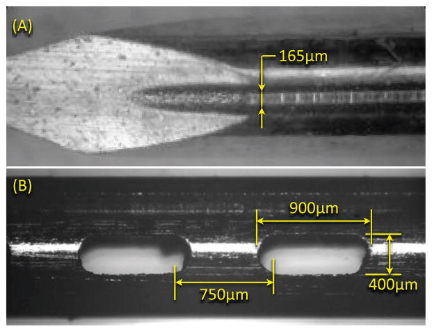
As noted, the needle consists of two parts: a solid stylet and a removable exterior sheath. The stylet is 1.008 mm in diameter, and the OD and ID of the outer sheath are 1.270 mm and 1.066 mm respectively. The stylet holds the sensing elements, and is made of MP35N (a nickel-cobalt based alloy); the sheath is Inconel 625. MP35N in any heat treated condition is particularly difficult to machine using traditional methods. Therefore we employed EDM to created the grooves and holes, using a wire diameter of 80 μ m. EDM also reduces the risk of shedding and embedding small ferromagnetic particles in the needle. Figure 4 shows a detail of the needle tip and one of the grooves.
Figure 4.
(A) Microscope image of needle tip and groove created using electric discharge machining. (B) Image of typical hole at needle tip.
EDM can only be performed on metallic parts, thus the plastic standard luer-lock base was removed with a heat gun, and reattached after machining. After re-assembly, the total metallic length of the needle from the plastic base was 147mm. The total fiber diameter (core + cladding) is 125 μ m, and FBG lengths are 5mm. The fibers were adhered in the grooves using a medical grade epoxy. The sensor locations were at 31 mm, 81 mm, 131 mm and 141 mm from the plastic base. The middle region of the final FBG set was centered over the array of holes at the tip.
5 Needle Calibration and Sensor Testing
The calibration of the first three sets of FBGs for bending profiles has been covered previously [27]. For tip force calibration, we apply known loads to the needle tip and monitor the changes in the wavelength from each FBG, assuming that each FBG measures axial strains at its centroid and that all FBGs experience the same strains as the needle material to which they are bonded.
As noted, the FBGs are sensitive to temperature variations. To calibrate for temperature, we put the needle in a controllable environmental chamber,2 set the temperature between 15–45°C, and waited for the temperature to stabilize before each measurement. The linear relationship between wavelength and temperature was found for each sensor on the needle. Each gage has a slightly different KT, due to the FBG manufacture and its bond to the needle, and is dominated by the thermal expansion of MP35N (1.37e-5/°C). The average value for KT among the 12 FBGs was 0.023 nm/°C.
It can be seen that the expected wavelength shifts due to mechanical strains are comparable to those from temperature changes. Recall from equation 2 that for constant temperature ΔλB = (1 − Pe)εzλB. Given the strain found from FEA for a 1N axial load (1.8e-5), and assuming a center wavelength of 1556 nm, a wave-length shift of 0.022 nm is expected at the upper FBG location. This means that the wavelength shift for a 1N axial load is similar to that for a temperature change of 1°C.
We assume a uniform temperature for each triplet of FBGs along the needle length. Hence, variations in temperature should affect each FBG equally. However, as seen seen in figure 3, the axial strain at the top FBG is almost double that of the lower FBGs due to the modified cross-section at the tip. Consequently, the effects of temperature and axial loading should be separable. However, to minimize the effects of temperature variation on force calibration, loads were applied at a known frequency to the needle tip using a dual-mode lever arm system3 with a high performance rotary moving coil motor. The lever arm applies controlled forces with a resolution of 1 mN with a 0.2% force to signal linearity over a range of frequencies from 1 to over 200 Hz. The lever arm was connected to the needle tip with a short spring to apply tip loads in x, y, or z, while the needle base was fixed. In the case of axial loading, the needle was held in tension to minimize strains due to bending. With the needle isolated in a foam-lined box, the dynamic force variations are easily distinguished from the much slower effects of ambient temperature variations.
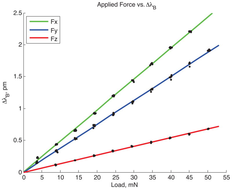
For calibration, we programmed the lever arm to produce sinusoidally varying forces at 20 rad/s. The wavelength data from the needle were filtered using 10th order Butterworth filters to high pass frequencies above 2Hz and low pass frequencies below 15Hz. A peak detection algorithm was used to find the wavelength shifts for the corresponding applied loads. Loads varying from 0.005 N to 0.05 N were tested. Figure 5 shows a typical ΔλB vs. Force plot for one FBG sensor, number 12, at the tip of the needle. FBG 12 is counter-clockwise from the top gage (FBG 10) when viewed from the xy plane. Due to its placement, it is more sensitive to loads in the x-direction than in the y-direction.
Figure 5.
Plot of wavelength shift to applied force for one FBG sensor at the needle tip (gage number 12).
5.1 Sensitivity: Forces and Frequency Response
Tests with the instrumented needle confirm the basic predictions of the FEM analysis. For a radial tip force of fy = 0.1 N, the predicted strain at the top gage (refer to figure 1B, Section A-A) is 3.145e-5, corresponding to an FBG wavelength shift of 0.038 nm. For an applied axial force of fz = 0.1 N, the average strain at the same gage corresponds to a measured wavelength shift of 0.0022 nm. More generally, as seen in the calibration data in figure 5, the FBG wavelength shifts vary linearly with applied tip forces in the x, y and z directions. From tests with the lever arm, it was found that the minimum detectable forces with reasonable resolution, without filtering FBG data, are approximately 0.008 N in the axial direction and 0.004 N in the radial x and y directions.
For the purposes of providing haptic feedback during minimally invasive surgery, the sensor response to small transient forces is of particular importance [20, 3]. Humans are sensitive to force variations in the range of tens to hundreds of Hz, with a peak sensitivity to vibrations around 250Hz [17]. For the case of needle manipulation in tissue, most of the frequencies of interest are in the tens of Hz, but when scraping hard or textured surfaces, vibrations with a frequency content of over 100 Hz are possible.
To test the frequency response of the needle and sensors, the needle was connected to a subwoofer, acting as a linear voice coil actuator, with a load cell at the center of its suspension pressing axially against the tip of the needle. The needle was adhered to the load cell through a small amount of polymer to prevent damage to the needle tip. A 5–500 Hz chirp signal was applied to the speaker through a function generator and amplifier, and data from the load cell and FBG sensors were collected. The transfer function between the load cell and the average response over the tip 3 FBGs was obtained using the ETFE (empirical transfer function estimation) method. The frequency range was split into 45 equally spaced bins and the transfer function was averaged across the bins and across multiple samples to minimize noise. As seen in figure 6 the frequency response of the needle is nearly flat over the frequency range tested, with some increase in amplitude above 200Hz, likely due to a small amount of bending that occurred at these higher frequencies.
Figure 6.
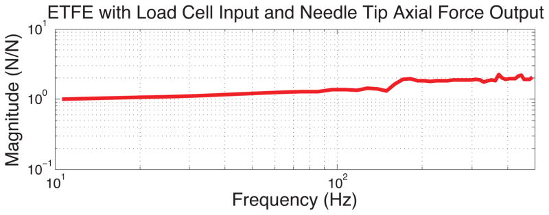
Plot of response to axial loading shows relatively constant amplitude over the frequencies of 10–500 Hz.
6 Results: Comparing Forces at Tip vs. Base
A test of the utility of the instrumented needle is to compare measured tip forces with those that could be sensed at the base, directly with a physician’s hand. For this comparison, the needle was affixed to a small 6-axis force/torque sensor (ATI Nano 174), which was mounted to a small plastic handle. An illustration of the arrangement is shown in figure 7. With this apparatus it is possible for a user to insert the needle into tissue phantoms while recording forces from the needle tip using the FBG sensors and from the needle base using the force/torque sensor. It is also possible to mount the apparatus to a linear stage, providing a single-axis approximation to a robot that might be remotely controlled to push the needle into tissue.
Figure 7.
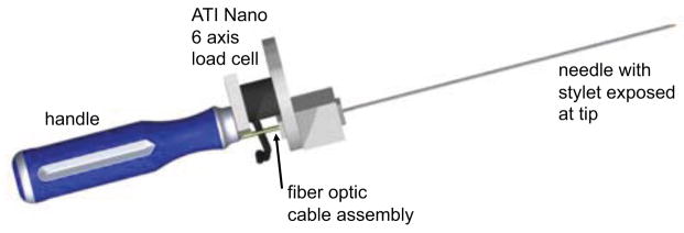
Needle fixed to a 6-axis force/torque sensor with handle for insertion experiments.
To show correlation between the FBG data and the force/torque sensor data, the handle assembly was first used to tap on a sample of urethane rubber (shore 60A durometer) in a water bath. The needle tip was pressed against the rubber, tapped three times and lifted completely off the rubber three times. The initial non-contact readings from both the force/torque sensor and the needle were subtracted from the readings during contact. For the needle, the wavelength common mode (i.e., the average wavelength shifts for the three distal FBGs) gives the wavelength change due to axial loading for comparison with the measured fz force from the force/torque sensor. As seen in figure 8 the recorded signals from the needle tip and the force/torque sensor at the needle base are nearly identical, with a lower noise floor in the case of the needle. This correspondence is to be expected as the tapping velocities were relatively low, so acceleration forces due to the mass of the needle did not significantly affect readings from the force/torque sensor in this case.
Figure 8.

Axial FBG data from needle tip compared to force data from needle base during tap testing.
A more interesting comparison is seen in figure 9. In this case the needle was pushed through a Plastisol5 phantom (2:1 ratio of plastic and softener). The needle went through the phantom’s skin, which included three layers of plastic and wax sheets, came in contact with a hard surface, and then was completely extracted [11]. Visible events in figure 9 include membrane contact and puncture, hitting a hard surface (e), and exiting membranes (f), which can be seen more clearly in the FBG data compared to the load cell. Beyond the higher signal to noise ratio from the instrumented needle, a major difference is that the stylet is housed inside a sheath which slides against tissues producing friction forces that are transmitted to the needle base. These friction forces felt at the base mask the effects of small variations in the tip forces. Secondly, for sudden changes in velocity, the force sensor at the needle base experiences inertial forces due to the mass of the needle. The FBG sensors near tip of the inner stylet do not experience either of these effects, and are therefore capable of discerning smaller dynamic forces at the tip.
Figure 9.

Axial FBG data from needle tip compared to force data from needle base during insertion in phantom: (a) initial contact of needle and phantom, (b) piercing through the first skin layer, (c) piercing first inner membrane, (d) piercing second inner membrane, (e) hitting hard surface, (f) extraction of needle from phantom.
7 Conclusions and Future Work
The data obtained from FBGs at the modified needle tip provide estimates of tip forces that are at least as accurate as those that can be obtained from a commercial, non MR-compatible force sensor. However, they can also provide information not easily detected from the base of the needle. In particular, when friction between the needle sleeve and tissue is significant, the tip sensors are better able to discriminate small variations in the tip forces. This instrumented needle has potential to validate models on needle interaction forces [28, 26, 10, 2, 15, 13] in vivo. The next step is to conduct controlled haptics experiments to determine whether subjects can easily detect events such as puncturing a membrane or scraping surfaces using tip force data. The purpose of this test would be to show whether the ability to sense tip forces directly (as one physician put it, ”to shrink one’s fingertips and put them at the tip of needle”) is useful in clinical practice. The ultimate test will be whether an augmented haptic display of tip force data can improve upon feedback based on forces sensed directly when holding a needle by its base.
Regarding the needle technology, useful improvements include better temperature compensation at the needle tip, for example by using using dual period or multiple diffraction order FBGs [6]. Also, for clinical use it may be necessary to fill the holes at the needle tip with a soft biocompatible polymer to prevent trapping tissue in them. The same basic technology presented here can also be adapted to other tool tips for direct and robot-assisted minimally invasive surgery.
Acknowledgments
This work has been supported by NIH PO1 CA159992, NIH SBIR R43-EB011822, an NSF Graduate Research Fellowship, and a Samsung Scholarship.
Footnotes
Model MR1815, Bracco Diagnostics, Princeton, NJ.
Intelligent Fiber Optic Systems Corporation (IFOS), Santa Clara, CA
Model S-1.2, Thermotron Industries, Holland, MI
Model 305B, Aurora Scientific Inc., Ontario, Canada
ATI Industrial Automation, Apex, NC
M-F Manufacturing Co, Fort Worth, TX
References
- 1.Abolhassani N, Patel R, Moallem M. Needle insertion into soft tissue: a survey. Med Eng Phys. 2007 May;29(4):413–31. doi: 10.1016/j.medengphy.2006.07.003. [DOI] [PubMed] [Google Scholar]
- 2.Barbe L, Bayle B, de Mathelin M, Gangi A. In vivo model estimation and haptic characterization of needle insertions. Int J Robot Res. 2007;26(11–12):1283–1301. [Google Scholar]
- 3.Bark K, McMahan W, Remington A, Gerwirtz J, Wedmid A, Lee DI, Kuchenbecker KJ. In vivo validation of a system for haptic feedback of tool vibrations in robotic surgery. Surgical Endoscopy. 2012 doi: 10.1007/s00464-012-2452-8. [DOI] [PubMed] [Google Scholar]
- 4.Black RJ, Zare D, Oblea L, Park Y-L, Moslehi B, Neslen C. On the gage factor for optical fiber grating strain gages. SAMPE. 2008;53 Paper ID 5166. [Google Scholar]
- 5.Blumenfeld P, Hata N, DiMaio S, Zou K, Haker S, Fichtinger G, Tempany C. Transperineal Prostate Biopsy Under Magnetic Resonance Image Guidance: A Needle Placement Accuracy Study. J Magn Reson Im. 2007;26:688–694. doi: 10.1002/jmri.21067. [DOI] [PubMed] [Google Scholar]
- 6.Brady G, Kalli K, Webb D, Jackson D, Reekie L, Archambault J. temperature using the first- and second-order diffraction wavelengths of Bragg gratings. IEE Proc Optoelectron. 1997;144(3):156–161. [Google Scholar]
- 7.Cao CGL, Zhou M, Jones DB, Schwaitzberg SD. Can surgeons think and operate with haptics at the same time? J Gastrointest Surg. 2007 Nov;11(11):1564–9. doi: 10.1007/s11605-007-0279-8. [DOI] [PubMed] [Google Scholar]
- 8.Culjat M, Bisley J, King C, Wottawa C, Fan R, Dutson E, Grundfest W. Tactile feedback in surgical robotics. In: Rosen J, Hannaford B, Satava R, editors. Surgical Robotics: Systems, Applications, and Visions. Springer; New York, NY, USA: 2011. pp. 449–468. [Google Scholar]
- 9.De Lorenzo D, Koseki Y, De Momi E, Chinzei K, Okamura AM. Experimental evaluation of a coaxial needle insertion assistant with enhanced force feedback. IEEE EMBC. 2011 Jan;2011:3447–50. doi: 10.1109/IEMBS.2011.6090932. [DOI] [PubMed] [Google Scholar]
- 10.DiMaio S, Salcudean S. Needle insertion modeling and simulation. IEEE T Robotic Autom. 2003;19(5):864–875. [Google Scholar]
- 11.Elayaperumal S, Christensen D, Bae J-H. Tip Force Sensing Needle in Tissue Phantom. Biomimetics and Dexterous Manipulation Laboratory, Stanford University; 2012. Available: http://www.youtube.com/watch?v=BlirNkqAGQ4. [Online] [Google Scholar]
- 12.Fischer GS, Iordachita I, Csoma C, Tokuda J, Dimaio SP, Tempany CM, Hata N, Fichtinger G. MRI-Compatible Pneumatic Robot for Transperineal Prostate Needle Placement. IEEE-ASME T Mech. 2008;13:295–305. doi: 10.1109/TMECH.2008.924044. [DOI] [PMC free article] [PubMed] [Google Scholar]
- 13.Goksel O, Salcudean S, DiMaio S. 3D needle-tissue interaction simulation for prostate brachytherapy. Medical Image Computing and Computer Assisted Intervention, MICCAI; 2005. pp. 827–834. [DOI] [PubMed] [Google Scholar]
- 14.Hill KO, Meltz G. Fiber Bragg grating technology fundamentals and overview. J Lightwave Technol. 1997;15:1263–1276. [Google Scholar]
- 15.Hing J, Brooks A, Desai J. Reality-based estimation of needle and soft-tissue interaction for accurate haptic feedback in prostate brachytherapy simulation. Robotics Research, STAR. 2007;28:34–48. [Google Scholar]
- 16.Iordachita I, Sun Z, Balicki M, Kang JU, Phee SJ, Handa J, Gehlbach P, Taylor R. A sub-millimetric, 0.25 mN resolution fully integrated fiber-optic force-sensing tool for retinal microsurgery. Int J CARS. 2009;4(4):383–390. doi: 10.1007/s11548-009-0301-6. [DOI] [PMC free article] [PubMed] [Google Scholar]
- 17.Jones LA, Sarter NB. Tactile Displays: Guidance for Their Design and Application. Human Factors: The Journal of the Human Factors and Ergonomics Society. 2008 Feb;50(1):90–111. doi: 10.1518/001872008X250638. [DOI] [PubMed] [Google Scholar]
- 18.Kozlowski P, Chang SD, Jones EC, Berean KW, Chen H, Goldenberg SL. Combined diffusion-weighted and dynamic contrast-enhanced MRI for prostate cancer diagnosis–correlation with biopsy and histopathology. J Magn Reson Im. 2006 July;24(1):108–13. doi: 10.1002/jmri.20626. [DOI] [PubMed] [Google Scholar]
- 19.Krieger A, Susil RC, Menard C, Coleman JA, Fichtinger G, Atalar E, Whitcomb LL. Design of a novel MRI compatible manipulator for image guided prostate interventions. IEEE T Bio-Med Eng. 2005;52:306–313. doi: 10.1109/TBME.2004.840497. [DOI] [PMC free article] [PubMed] [Google Scholar]
- 20.Kuchenbecker KJ, Gewirtz J, Mcmahan W, Standish D, Martin P, Bohren J, Mendoza PJ, Lee DI. VerroTouch : High-Frequency Acceleration Feedback for Telerobotic Surgery. Euro-Haptics. 2010:189–196. [Google Scholar]
- 21.Ledermann C, Hergenhan J, Weede O, Woern H. Combining shape sensor and haptic sensors for highly flexible single port system using Fiber Bragg sensor technology. IEEE/ASME MESA. 2012 July;:196–201. [Google Scholar]
- 22.Mishra V, Singh N, Tiwari U, Kapur P. Fiber grating sensors in medicine: Current and emerging applications. Sensor Actuat A-Phys. 2011 June;167(2):279–290. [Google Scholar]
- 23.Nezhat F. Minimally invasive surgery in gynecologic oncology: laparoscopy versus robotics. Gynecol Oncol. 2008 Nov;111(2 Suppl):S29–32. doi: 10.1016/j.ygyno.2008.07.025. [DOI] [PubMed] [Google Scholar]
- 24.Okamura A, Verner L, Yamamoto T, Gwilliam J, Griffiths P. Force feedback and sensory substitution for robotassisted surgery. In: Rosen J, Hannaford B, Satava R, editors. Surgical Robotics: Systems, Applications, and Visions. Springer; New York, NY, USA: 2011. pp. 419–448. [Google Scholar]
- 25.Okamura AM. Haptic feedback in robot-assisted minimally invasive surgery. Curr Opin Urol. 2009 Jan;19(1):102–7. doi: 10.1097/MOU.0b013e32831a478c. [DOI] [PMC free article] [PubMed] [Google Scholar]
- 26.Okamura AM, Simone C, O’Leary MD. Force modeling for needle insertion into soft tissue. IEEE T Bio-Med Eng. 2004 Oct;51(10):1707–16. doi: 10.1109/TBME.2004.831542. [DOI] [PubMed] [Google Scholar]
- 27.Park Y-l, Elayaperumal S, Daniel B, Ryu SC, Shin M, Savall J, Black RJ, Moslehi B, Cutkosky MR. Real-Time Estimation of 3-D Needle Shape and Deflection for MRI-Guided Interventions. IEEE-ASME T Mech. 2010;15(6):906–915. doi: 10.1109/TMECH.2010.2080360. [DOI] [PMC free article] [PubMed] [Google Scholar]
- 28.Simone C, Okamura A. Modeling of needle insertion forces for robot-assisted percutaneous therapy. IEEE ICRA. 2002;2:2085–2091. [Google Scholar]
- 29.Sung G, Gill I. Robotic laparoscopic surgery: a comparison of the DA Vinci and Zeus systems. Urology. 2001;58:893–898. doi: 10.1016/s0090-4295(01)01423-6. [DOI] [PubMed] [Google Scholar]
- 30.Tokuda J, Fischer GS, DiMaio SP, Gobbi DG, Csoma C, Mewes PW, Fichtinger G, Tempany CM, Hata N. Integrated navigation and control software system for MRI-guided robotic prostate interventions. Comput Med Imag Grap. 2010 Jan;34(1):3–8. doi: 10.1016/j.compmedimag.2009.07.004. [DOI] [PMC free article] [PubMed] [Google Scholar]
- 31.Tsekos NV, Khanicheh A, Christoforou E, Mavroidis C. Magnetic Resonance - Compatible Robotic and Mechatronics Systems for Image-Guided Interventions and Rehabilitation: A Review Study. Annu Rev Biomed Eng. 2007;9:351–387. doi: 10.1146/annurev.bioeng.9.121806.160642. [DOI] [PubMed] [Google Scholar]
- 32.van der Meijden O, Schijven M. The value of haptic feedback in conventional and robot-assisted minimal invasive surgery and virtual reality training: a current review. Surgical Endoscopy. 2009 June;23(6):1180–90. doi: 10.1007/s00464-008-0298-x. [DOI] [PMC free article] [PubMed] [Google Scholar]
- 33.Washio T, Chinzei K. Needle Force Sensor, Robust and Sensitive Detection of the Instant of Needle Puncture. MICCAI. 2004:113–120. [Google Scholar]
- 34.Zhang L, Qian J, Zhang Y, Shen L. On SDM/WDM FBG sensor net for shape detection of endoscope. IEEE ICMA. 2005;4:1986–1991. [Google Scholar]


