

Abstract
This paper presents calibration and user test results of a 3-D tip-force sensing needle with haptic feedback. The needle is a modified MRI-compatible biopsy needle with embedded fiber Bragg grating (FBG) sensors for strain detection. After calibration, the needle is interrogated at 2 kHz, and dynamic forces are displayed remotely with a voice coil actuator. The needle is tested in a single-axis master/slave system, with the voice coil haptic display at the master, and the needle at the slave end. Tissue phantoms with embedded membranes were used to determine the ability of the tip-force sensors to provide real-time haptic feedback as compared to external sensors at the needle base during needle insertion via the master/slave system. Subjects were able to determine the position of the embedded membranes with significantly better accuracy using FBG tip feedback than with base feedback using a commercial force/torque sensor (p = 0.045) or with no added haptic feedback (p = 0.0024).
I. INTRODUCTION
In minimally invasive surgery, interactions between the surgical tool and surrounding tissues provide important information to the physician. The potential advantages of haptic feedback in medical applications include reduction of surgical errors and faster operation times in practice, as well as psychomotor skill acquisition when used during training [1]. In addition to force feedback, interpretation of texture, shape and consistency of objects can be useful to physicians if implemented in endoscopic tools [2]. Relying purely on visual cues for estimating interaction forces has been shown to saturate cognitive load [3]. Furthermore, it has been shown that tissue grasping and suture tying without force feedback leads to slippage and tissue damage in both laparascopic [4] and robot-assisted interventions [5]. In robot-assisted surgeries, absence of haptic feedback prolonged procedures including colorectal surgery, Nissen fundoplication, cholecystectomy and coronary artery bypass [6]–[9].
Numerous investigations in robot-assisted minimally invasive surgery have recognized the need for tactile feedback [10]–[12]. However, despite the recognized importance of haptic sensations, progress in creating instrumented minimally invasive tools has been slow due to the technical challenges associated with creating tools with sensors that are miniature, robust, sterilizable, biocompatible and economical. One of the few sensing solutions that meets these requirements is optical fiber sensing using fiber Bragg gratings (FBG). We present a system that provides haptic feedback using the signals from FBG sensors embedded in a biopsy needle for force sensing in medical applications.
When a needle consists of an inner stylet and a surrounding sheath, the measurement of tip forces is complicated by frictional forces along the sheath. Other research groups have outfitted a needle with two axial force cells at its base, one connected to the stylet and the other to the sheath [13], [14]. They observed that at the instant of puncture on a tissue surface, the force output from the sheath increased while that of the stylet decreased [14]. An expansion on a similar co-axial needle setup monitored membrane puncture forces as measured by the cutting force on the stylet versus the frictional force on the sheath [15]. They reported a higher success rate of user identification of membrane puncture when relying on cutting forces over cutting plus frictional forces.
We previously described a force-sensing needle with embedded FBG sensors for applications in MRI-guided interventions [16]. Although a large advantage of FBG technology is its immunity to electro-magnetic interference, the sensors can be used for non-MRI interventions as well due to their small size and high resolution. Optical fibers with Bragg gratings are an attractive solution due to their ability to measure optical wavelength shifts corresponding to very small strains. Other advantages include physical robustness and the ability to perform optical multiplexing so that strain data can be obtained from multiple FBGs along a single fiber. Because FBGs are sensitive to temperature, it is important to provide temperature compensation [17]. Medical applications have incorporated FBGs on biopsy needles, catheters and other minimally invasive tools for shape detection and force sensing [18]–[22].
In this paper, we demonstrate the use of a tip-force sensing needle for haptic feedback in benchtop experiments, in order to ascertain its utility over a traditional 6-axis force-torque sensor external to the tool. We describe the results of controlled needle insertion task tests in which subjects received haptic feedback dependent on the needle tip-force (FBG sensors) or the frictional force as measured from the base (commercial force/torque sensor) to detect membranes embedded in tissue phantoms. We also tested cases in which the subjects received no added feedback. Other advances from our previous work include new force calibration methods and an integrated final system with haptic feedback.
II. METHODS AND MATERIALS
A. Needle Description
An off-the shelf 18 ga MRI compatible needle1 was modified with embedded optic fibers with fiber Bragg grating (FBG) strain sensors (Fig. 1). The needle’s inner stylet has three fibers, 120° apart in the needle cross-section, and slotted features at the tip to improve its sensitivity to axial loading. A description of the fabrication and design of this needle is found in [16].
Fig. 1.

(A) CAD rendering of needle prototype and sensor locations. (B) Detail of needle stylet, showing tip force sensing features and modified cross-section with specified dimensions. (C) Microscope image of actual dimensions of final needle. All dimensions in mm.
1) Fiber Bragg Grating Sensors
FBGs work by reflecting light at a wavelength that shifts in proportion to mechanical and thermal strain on the fiber. The wavelength shift is often simplified as:
| (1) |
where Kε and KT are constants representing the sensitivity to mechanical strains and temperature variations, respectively.
The needles used in these experiments are made of MP35N alloy and have an FBG at 4 locations on each of 3 fibers along the length, for a total of 12 FBGs in the needle. The center wavelengths for the FBGs varied from 1528 nm to 1565 nm. The FBGs at the first of the three locations (numbered 1 through 9) are used primarily for shape sensing along the needle. It is assumed the temperature at each sensor location (triplet of FBGs) is the same through the needle cross-section. Each triplet has a calibration matrix associated with it:
| (2) |
where kxz and kyz are the curvatures about the XZ and YZ needle planes, ΔT is the change in temperature and i = 1, 2, or 3.
The final FBG locations (10, 11, 12) are used for force sensing. When the needle is modeled as a cantilever beam, the moment at the free end is zero. Thus, the tip sensors are not very useful for curvature sensing. However, they are ideally placed to measure loads at the needle tip, without measuring friction along the needle shaft nor inertial effects past the sensor location. Because there is negligible mass at the needle tip, the FBGs at the fourth location can more precisely measure contact loading. Linear relationships between Δλj for j = 10, 11, 12 can be found for the transverse and axial loads (Fx, Fy, Fz).
B. Calibration Experiments
In the calibration method and experiments described, we used a commercial optical interrogator2, which sampled the FBG wavelengths at 2 kHz, with 0.1 pm resolution.
1) Wavelength Shift and Temperature
When the needle is inserted into the human body, the change in temperature from ambient temperature (typically 20°C) to body temperature at 37°C produces a significant thermal strain which, for a symmetric needle cross section, is indistinguishable from the effect of a purely axial force. The wavelength shift due to a 1°C change in temperature is comparable to the wavelength shift due to a 1 N change in axial force, which is well within the range of forces that we desire to measure.
One method to separate thermal strain and axial loads is by utilizing a filter for the reduction of thermal noise. Wavelength changes caused by thermal variations are slow compared to those produced by dynamic loads on the needle. The filtering frequency range is selected by analyzing the lowest and highest frequencies of forces during needle biopsy interventions. Most of the lowest frequencies are in the tens of Hz, but when the needle is scraped against relatively hard, textured surfaces (e.g. scar tissue), or when it punctures a membrane, the highest frequencies can reach over 100 Hz. Thermal changes however, occur on the order of 1 Hz.
2) Wavelength Shift and Force
Because the arrangement of the distal FBG sensors on the needle and the cross sectional shape of the needle tip are asymmetric, the strains and the changes of wavelength will be different for each gauge when radial loads are applied in different directions. This is observed in Fig. 2, which compares the wavelength shifts for the third (7, 8, 9) and fourth (10, 11, 12) sets of FBGs under transverse loading in varying directions. A similar approach to determine the angle between fibers was taken by [23]. The load direction was controlled with an apparatus (Fig. 3) that allowed for rotation of the needle base in 5° increments, while the tip was loaded with a micro-lever arm3 that applies controlled dynamic forces with frequencies up to 100 Hz. Forces were also measured with a commercial ATI Gamma force sensor4. The needle was similarly loaded in tension using the lever arm to calibrate the wavelength shift due to axial loading. Loads were applied at 5 Hz from −0.25 to 0.25 N.
Fig. 2.

Data of wavelength shift for varying direction of applied transverse load at the (A) third and (B) fourth sensing locations.
Fig. 3.
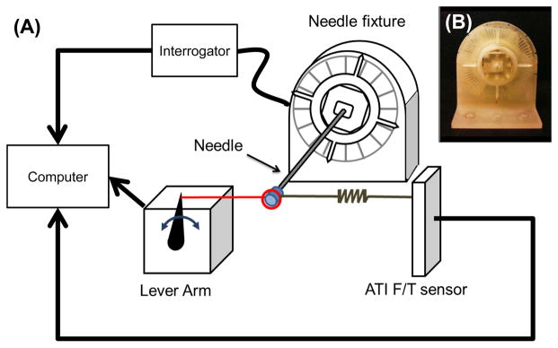
(A) Schematic of the needle calibration set up to measure wavelength shift due to various transverse loads while rotating the needle base 0° to 360°. (B) 3-D printed apparatus to fix the needle every 5°.
The FBG data were filtered with a 10th order Butterworth filter to high pass frequencies above 2 Hz and low pass frequencies below 15 Hz to eliminate the thermal noise. A peak detection algorithm was used to find the wavelength shifts for the corresponding applied loads. Loading the needle dynamically with the micro-lever arm allows us to eliminate temperature effects and explore the sensors’ response to dynamic tip forces.
C. Phantom Materials for Physiological Tactility
To investigate materials to best mimic human tissue for benchtop testing of our force-sensing needle, we made phantom tissues based on materials used in the literature [24]–[26]. Phantom tissue materials included 2:1 and 4:1 ratios of PVC plastic to softener5 and agar. The membranes made of polypropylene and polyester films were placed between blocks of phantom tissue as shown in Fig 4
Fig. 4.
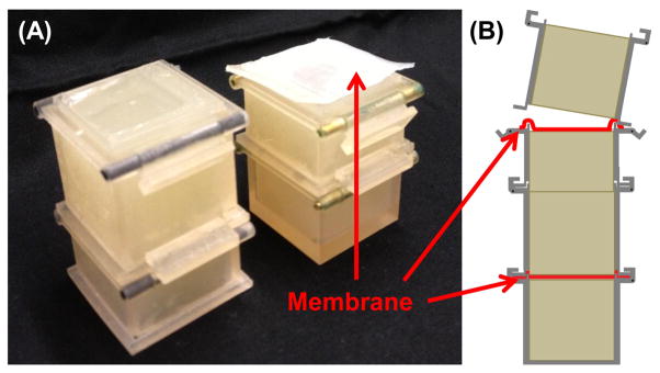
Reconfigurable membrane and tissue phantom (A) photo and (B) assembly diagram.
To evaluate the phantoms we interviewed doctors in the Diagnostic Radiology department at Stanford Medical Center (Stanford, CA). Four physicians with an average of 24 years of experience since residency, and one fellow, were given the sample phantoms and a biopsy needle, then asked to describe the feeling during insertion by hand.
One interventional radiologist described the agar phantom as what he’s used to feeling for normal tissue, whereas the PVC phantom felt more like a breast tumor. Another senior physician said the agar feels like fat, normal liver and normal tissue, whereas the 2:1 PVC phantom felt like a “more convincing” real tumor. Next, a phantom was prepared with alternating agar and PVC blocks, with polypropylene film between the layers. One doctor feeling this phantom said the PVC with membranes felt realistic for going through a membrane, however the phantom had a lot of resistance. Going from agar to the membrane felt like hitting a calcified lesion. The PVC felt like breast tissue, the agar felt like fat, and a cyst would feel like the membrane against agar.
With the multi-material phantom (agar, membrane, PVC, membrane, agar), we covered the phantom and gave the physicians a task: to stop insertion when they thought they had reached the second membrane. One physician said it was difficult to feel the second membrane, yet was successful in all trials. The physician also commented that drag is felt when the needle gets into the second agar layer. Another physician said this task “feels like thyroid biopsy,” in which the fascia layer where anesthesia is delivered can be felt. He was also successful in feeling each membrane and commented on the resistance through the PVC layer. Drawing from experience in real procedures, he said, “The deeper you go, the less sensitive your fingers are. In the liver, once the needle is 5 to 7 cm in, it gets difficult to feel anything.” Physicians expressed desire for haptic feedback and said that after years of doing biopsies, “You learn to trust your feel as much as your eyes.”
Overall, it was decided that agar better mimicked healthy soft tissue, and the PVC phantoms mimicked tumors and tougher tissue, yet caused a lot of drag and high frictional forces along the needle during insertion.
D. Haptics Experiments
1) Design of the System
We designed a single degree of freedom (1-DOF) master/slave system and haptic display as shown in Fig. 5. To restrain the movement of the system in 1-DOF, a rail and two carriages6 were used. On the first carriage, an external 6-axis force/torque sensor7 and the FBG sensor embedded needle were mounted; this represents the slave side of an ideal 1-DOF teleoperation system. The master side consists of a voice-coil haptic display which displays the dynamic force information read from either the base (using the ATI force/torque sensor) or from the tip of the needle (using the embedded FBGs) by displacement of the display’s diaphragm. A block of PVC rubber (Plastisol in 2:1 plastic:softener ratio) was used to isolate the master from vibrations in the slave during needle insertion – as would be the case when using an electromechanical master/slave system. However, the compliant master/slave coupling does transmit large, low-frequency forces, freeing the voice coil actuator to produce vibrations instead of kinesthetic forces. Thus, the 1-DOF master/slave system with its damped, compliant coupling and the voice-coil haptic display together provide a simulation of the feeling to be expected from an electromechanical master/slave system augmented with vibrational haptic feedback.
Fig. 5.

Master/slave system restricting insertion motions along the axial direction, with haptic display as used in the benchtop experiments.
To test the isolation of the master and slave platforms, two accelerometers were attached to the master and slave side, and the slave side was struck by hammer several times. The set up was the same as for the haptic experiments, with the damping block placed between the master and slave such as in Fig. 5. The average cut off frequency of the block from 6 trials was 17.7 Hz. The frequency response data from a test is shown in Fig 7.
Fig. 7.
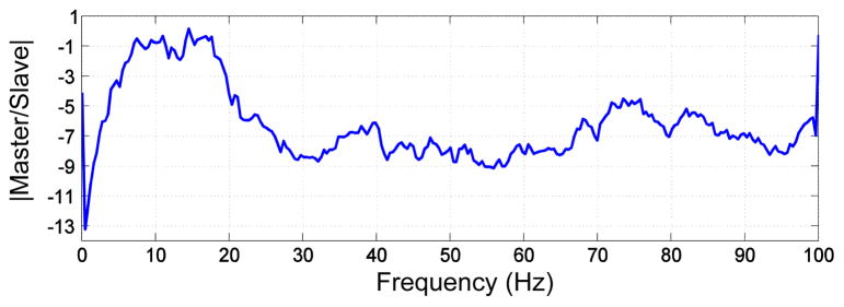
Frequency response of the PVC damping block from a resonance test.
Haptic feedback was given based on the tip FBG sensors or the ATI force/torque sensor at the needle base. There is some baseline noise in both the FBG and external force/torque sensor measurements. The FBG sensor system had a noise level equivalent to 0.07 N at the master display; the force/torque sensor had a noise level equivalent to 0.16 N. This noise would produce noticeable displacements at the haptic display if played directly. Therefore the baseline noise is filtered for both the force/torque and FBG data using a point by point median filter. The window of the median filter is minimized such that the hardware execution loop can run at 1 to 2 kHz, which minimizes any latency in forces felt by the user. Because the FBG readings are sensitive to temperature, a secondary point by point mean filter is applied to the wavelength data. This filter gathers data for 800 samples and establishes a baseline to track thermal drift, which is subtracted from the original data. The mean filter does not affect the speed of the haptic system, but is used as a comparison for the current wavelength shifts which, if above a certain threshold, are considered to be due to physical contact and not temperature change. In this way, the mean filter acts as a low pass frequency filter and is used to measure slow changes in the FBG data and reduce effects of temperature.
We used an sbRIO8 data acquisition board; an Ethernet switch from the optical interrogator, control computer and sbRIO; and custom software written in LabView to drive the haptic display. While the needle tip is loaded, either the filtered reading from the most sensitive sensor to axial loading (FBG number 10, which lies on top of the slotted holes) or from a voltage output from the external force/torque sensor, is used to drive the voice coil actuator. The voice coil is controlled by a linear current amplifier which receives an analog voltage from the sbRIO. Gains on the sensor data are set such that the voice coil actuator produces the same displacement for the same load as measured by the base ATI sensor and the tip FBG sensors.
2) User Experiments
To demonstrate the feasibility of using the tip-force sensing needle for haptic feedback, we designed an experiment that asked users to insert the needle via the 1-DOF master/slave system into an agar phantom with membranes placed at different locations. The users pushed from their palms on the haptic display to insert the needle into the tissue phantom. While inserting the needle, they felt the displacement from the front side of the haptic device through their fingertips. They were asked to stop insertion when they felt they encountered a membrane. The membranes were made of Shore 2A durometer silicone9, cast inside molds 0.1–0.3 mm thick with embedded tissue paper10 to mimic the connective tissue layer in natural visceral membranes. Trials were randomized in the position of the membrane along the phantom, and whether or not the subject received haptic feedback. In the no feedback case, white noise indistinguishable from the noise encountered for the FBG and external force/torque sensors was played to the voice-coil. The insertion distance was measured via a fixed digital caliper along the 1-DOF stage. The membrane could be placed anywhere from 2 to 10 cm along the agar block. The subject was asked to stop insertion when they believed they encountered a membrane, then the insertion distance was recorded.
III. RESULTS
A. Force Calibration Results
Fig. 8 shows the actual and estimated loads for all the data from the loading and temperature calibration tests. The best method for calibration was to filter out thermal effects and use a 3×3 calibration matrix to map wavelength shifts at FBGs 10, 11, 12 to (Fx, Fy, Fz) at the tip. The mean error of force calibration for x, y and z directions are −1.1 mN (std=8.4 mN), −0.4 mN (std=16.5 mN) and −1.2 mN (std=4.4 mN) respectively.
Fig. 8.

Actual and estimated tip loads in Fx, Fy, and Fz for all loading experiments. Data from Case A: when the transverse loading was varied, B: when only axial loading was applied, C: when only forces in the y direction were applied, and D : when only forces in the x and y directions were applied.
B. Haptics Benchtop Test Results
Of 87 insertions by 10 healthy subjects, the success rate of identifying membrane encounter was 75.0% with feedback from the needle’s FBG tip sensors, 48.3% from the external force/sensor at the needle base, and 33.3% in the case of no haptic feedback. The test subjects were healthy, approximately half male and female, and with an average age of 28.5 years; however, they were not physicians experienced in needle biopsies.
A success was characterized as stopping the needle tip within 18 mm of the actual membrane location. The distance threshold was set because contact can occur before puncture. The membrane stretches and can deform significantly before it is pierced, at which point the needle tip will experience the greatest change in force. Furthermore, after trying the experiment protocol in a 3-D cone beam CT scanner (Artis Zeego, Siemens, Munich, Germany), we noticed that even when an obvious membrane puncture was detected, it was difficult to stop the stage within a centimeter past the membrane. From various trials and measurements between the needle tip and membrane as seen on the CT images, we set the success threshold to 18 mm.
Paired t-test calculations were used to compare the success rate among the subjects for two modes against the FBG sensors: a no haptic feedback mode that only contains random noise (set to match the background noise with either the ATI force/torque sensor of the FBG sensors), and a force/torque mode that senses the forces at the base of needle (ATI mode). From a one-tailed test as to whether FBG feedback was better than ATI feedback, there was a statistically significant difference between two modes (mean success FBG - ATI = 0.255, within a 95% confidence interval, t = 1.896, p-value = 0.045). When comparing the success rate of the ATI based mode versus no haptic feedback there is also a significant difference (mean success ATI - No feedback = 0.264, within a 95% confidence interval, t = 1.54, p-value = 0.079). FBG compared to no feedback was very significant (mean success FBG - No feedback = 0.519, within a 95% confidence interval, t = 3.71, p-value = 0.0024). These results suggest that the FBG tip sensing mode helps subjects to detect the membrane more successfully than other two modes.
Reasons for failure in all cases included when a user “Did not feel anything,” meaning he/she moved the stage through the entire phantom without detecting a membrane, and “Missing a membrane,” meaning that he/she felt the membrane after puncturing it. “Sensing a non-existent membrane” was a false positive error.
The FBG based feedback had only two failure cases of no membranes sensed, whereas the base force/torque sensor and no feedback cases had seven and five failures respectively of this type. The majority of FBG based feedback failures (62%) were due to the subject just passing the membranes. In the cases of just missing a membrane, if the success threshold was set at 10, the average distance between the needle tip and the threshold was 6.7 mm for the cases with FBG feedback, 17.5 mm for the external sensor, and 8.7 mm for no feedback. Therefore, users were closer to stopping just after the membrane in the cases in which feedback was based on the FBG sensors over the other cases.
IV. DISCUSSION
It is difficult to apply pure axial loads to the needle, and the sensitivity of the needle is considerably higher for radial loads than axial loads. Hence, even when inserting the needle with a single degree of freedom apparatus, it is likely that small lateral loads at the needle tip are a large fraction of the measured tip force and corresponding haptic display. In practice, this may not be particularly important as membrane puncture and other needle/tissue interactions are often accompanied by a combination of axial and radial dynamic forces. Moreover, for forces with frequencies in the tens of Hz and up to a few hundred Hz, the dominant human sensing mechanism is likely to be the Pacinian corpuscles, which have large receptive fields and are not particularly directional [27].
Although small changes in temperature can produce strains comparable to those of forces at the needle tip, it was possible to minimize these effects by using dynamic forces during calibration, and by high-pass filtering during insertions. In particular, it was found that a secondary filter was helpful in eliminating a large jump in the FBG sensor readings due to temperature change when the tip moved from air into the agar block; however some variation was still present, which could be mistaken for a membrane puncture. Therefore, in the haptics experiments, we made the starting position of each trial have the needle tip just inside the agar block such that there would not be a noticeable change due to temperature during insertion.
It was also observed that due to the secondary filtering, if the stage was moved too slowly, it was difficult to pick up a significant change in applied load. It may be that the secondary filter and threshold parameters need to be adjusted to better remove effects of temperature while allowing for detection of higher frequency changes in axial load during membrane deformation and puncture. In addition, human haptic perception is better at detecting fast changes than slow changes in forces.
Some subjects discovered that dithering the stage (moving the stage gently back and forth with small quick motions) made it easier to feel the membranes. Dithering is a human strategy that helps us to detect small changes, by making them dynamic. It also takes advantage of a reduction in system friction, because the dynamic coefficient of friction is usually less than the static coefficient. Hence, the net system friction is reduced.
V. CONCLUSIONS AND FUTURE WORK
Tip forces can easily be discerned by our sensorized needle, especially above 0.05 N, when changes due to temperature are filtered out. Future methods to improve axial and temperature calibration may include the use of dual period FBGs or the use of full spectrum FBG data. Other feasible approaches to measure force and temperature independently include bilateral cantilever beams [28], the use of the bifringence effect [29], and hybrid dual-grating sensors [30].
The haptic feedback system will be improved by reducing friction on the linear stage, and exploring different filtering methods to better separate thermal effects from axial loading. We will also explore other methods for the haptic display such as smaller voice coils, tactors, small motors and piezoelectric actuators, while testing the display of multi-directional loading. The primary requirements are a wide frequency range, minimal latency, and crisp reproduction of contact force transients.
Although the haptic feedback test results presented here used non-experts as subjects, it is shown that the FBG embedded needle helps significantly (p<0.05) in identifying needle tip contact with a membrane in a tissue phantom. Therefore, experts in needle driven procedures may be more conscious of loading at the needle, even through the 1-DOF master/slave mechanism, and may be faster at learning how to respond to the haptic feedback device. Future work includes running these tests with clinicians as subjects, in a more clinical setting. We would also like to run some multiple membrane tests, in which the subject drives the needle through the whole phantom and reports on the number of membranes they believe they passed. A more complete set of data will require more trials per subject, giving additional time for training with the haptic feedback display. More trials will also be necessary to draw conclusions on the insertion depth and accuracy of the ability to detect membranes with haptic feedback. We hypothesize accuracy will not be affected for feedback based on contact forces as measured from the needle tip, however deeper membranes will be more difficult to sense based on frictional forces as measured from the needle base.
Fig. 6.

Schematic of the mechanical and software parts of the haptic feedback system.
Acknowledgments
This work was supported in part by NIH P01 CA159992, the NSF GRFP, and the Kwanjeong Educational Foundation.
Footnotes
Model MR1815, Bracco Diagnostics, Princeton, NJ
Model sm130-700, Micron Optics, Atlanta, GA
Model 305, Aurora Scientific Inc., Ontario, Canada
ATI Industrial Automation, Inc., Apex, NC
Plastisol, M-F Manufacturing Co, Fort Worth, TX
DryLin T TW-01-15, Igus Inc., Kln, Germany
Nano17, ATI Industrial Automation, Inc., Apex, NC
Model 9632, National Instruments Corp., Austin, TX
Dragon Skin FX-Pro, Smooth On Inc, Easton, PA
34155, Kimwipes, Kimberly-Clark, Irving, TX
Contributor Information
Santhi Elayaperumal, Email: santhie@stanford.edu.
Jung Hwa Bae, Email: jbae7@stanford.edu.
Bruce L. Daniel, Email: bdaniel@stanford.edu.
Mark R. Cutkosky, Email: cutkosky@stanford.edu.
References
- 1.van der Meijden O, Schijven M. The value of haptic feedback in conventional and robot-assisted minimal invasive surgery and virtual reality training: a current review. Surgical Endoscopy. 2009 Jun;23(6):1180–90. doi: 10.1007/s00464-008-0298-x. [DOI] [PMC free article] [PubMed] [Google Scholar]
- 2.Bholat OS, Haluck RS, Kutz RH, Gorman PJ, Krummel TM. Defining the role of haptic feedback in minimally invasive surgery. Studies in health technology and informatics. 1999;62:62–66. [PubMed] [Google Scholar]
- 3.Cao CGL, Zhou M, Jones DB, Schwaitzberg SD. Can surgeons think and operate with haptics at the same time? J Gastrointest Surg. 2007 Nov;11(11):1564–9. doi: 10.1007/s11605-007-0279-8. [DOI] [PubMed] [Google Scholar]
- 4.Balazs M, Feussner H, Hirzinger G, Omote K, Ungeheuer A. A new tool for minor-access surgery. IEEE Engineering in Medicine and Biology Magazine. 1998;17 doi: 10.1109/51.677168. [DOI] [PubMed] [Google Scholar]
- 5.Bethea BT, Okamura AM, Kitagawa M, Fitton TP, Cattaneo SM, Gott VL, Baumgartner WA, Yuh DD. Application of haptic feedback to robotic surgery. Journal of laparoendoscopic & advanced surgical techniques Part A. 2004;14:191–195. doi: 10.1089/1092642041255441. [DOI] [PMC free article] [PubMed] [Google Scholar]
- 6.Delaney CP, Lynch AC, Senagore AJ, Fazio VW. Comparison of robotically performed and traditional laparoscopic colorectal surgery. Diseases of the colon and rectum. 2003;46:1633–1639. doi: 10.1007/BF02660768. [DOI] [PubMed] [Google Scholar]
- 7.Morino M, Pellegrino L, Giaccone C, Garrone C, RF Randomized clinical trial of robot-assisted versus laparoscopic Nissen fundoplication. British Journal of Surgery. 2006;93:554–558. doi: 10.1002/bjs.5325. [DOI] [PubMed] [Google Scholar]
- 8.Nakadi IE, Mélot C, Closset J, DeMoor V, Bétroune K, Feron P, Lingier P, Gelin M. Evaluation of da Vinci Nissen fundoplication clinical results and cost minimization. World journal of surgery. 2006;30:1050–1054. doi: 10.1007/s00268-005-7950-6. [DOI] [PubMed] [Google Scholar]
- 9.Kornprat P, Werkgartner G, Cerwenka H, Bacher H, El-Shabrawi A, Rehak P, Mischinger HJ. Prospective study comparing standard and robotically assisted laparoscopic cholecystectomy. Langenbeck’s archives of surgery/Deutsche Gesellschaft fur Chirurgie. 2006;391:216–221. doi: 10.1007/s00423-006-0046-4. [DOI] [PubMed] [Google Scholar]
- 10.Culjat M, Bisley J, King C, Wottawa C, Fan R, Dutson E, Grundfest W. Tactile feedback in surgical robotics. In: Rosen J, Hannaford B, Satava R, editors. Surgical Robotics: Systems, Applications, and Visions. New York, NY, USA: Springer; 2011. pp. 449–468. [Google Scholar]
- 11.Okamura A, Verner L, Yamamoto T, Gwilliam J, Griffiths P. Force feedback and sensory substitution for robotassisted surgery. In: Rosen J, Hannaford B, Satava R, editors. Surgical Robotics: Systems, Applications, and Visions. New York, NY, USA: Springer; 2011. pp. 419–448. [Google Scholar]
- 12.Okamura AM. Haptic feedback in robot-assisted minimally invasive surgery. Curr Opin Urol. 2009 Jan;19(1):102–7. doi: 10.1097/MOU.0b013e32831a478c. [DOI] [PMC free article] [PubMed] [Google Scholar]
- 13.Kataoka H, Washio T, Chinzei K, Mizuhara K, Simone C, Okamura AM. MICCAI. Springer-Verlag; Berlin Heidelberg: 2002. Measurement of the Tip and Friction Force Acting on a Needle during Penetration; pp. 216–223. [Google Scholar]
- 14.Washio T, Chinzei K. Needle Force Sensor, Robust and Sensitive Detection of the Instant of Needle Puncture. MICCAI. 2004:113–120. [Google Scholar]
- 15.De Lorenzo D, Koseki Y, De Momi E, Chinzei K, Okamura AM. Experimental evaluation of a coaxial needle insertion assistant with enhanced force feedback. IEEE EMBC. 2011 Jan;:3447–50. doi: 10.1109/IEMBS.2011.6090932. [DOI] [PubMed] [Google Scholar]
- 16.Elayaperumal S, Bae JH, Christensen D, Cutkosky MR, Daniel BL, Black RJ, Costa JM. MR-compatible biopsy needle with enhanced tip force sensing. IEEE World Haptics Conference; 2013; pp. 109–114. [DOI] [PMC free article] [PubMed] [Google Scholar]
- 17.Brady G, Kalli K, Webb D, Jackson D, Reekie L, Archambault J. Simultaneous measurement of strain and temperature using the first- and second-order diffraction wavelengths of Bragg gratings. IEE Proc Optoelectron. 1997;144(3):156–161. [Google Scholar]
- 18.Iordachita I, Sun Z, Balicki M, Kang JU, Phee SJ, Handa J, Gehlbach P, Taylor R. A sub-millimetric, 0.25 mN resolution fully integrated fiber-optic force-sensing tool for retinal microsurgery. Int J CARS. 2009;4(4):383–390. doi: 10.1007/s11548-009-0301-6. [DOI] [PMC free article] [PubMed] [Google Scholar]
- 19.Ledermann C, Hergenhan J, Weede O, Woern H. Combining shape sensor and haptic sensors for highly flexible single port system using Fiber Bragg sensor technology. IEEE/ASME MESA. 2012 Jul;:196–201. [Google Scholar]
- 20.Mishra V, Singh N, Tiwari U, Kapur P. Fiber grating sensors in medicine: Current and emerging applications. Sensor Actuat A-Phys. 2011 Jun;167(2):279–290. [Google Scholar]
- 21.Park Y-l, Elayaperumal S, Daniel B, Ryu SC, Shin M, Savall J, Black RJ, Moslehi B, Cutkosky MR. Real-Time Estimation of 3-D Needle Shape and Deflection for MRI-Guided Interventions. IEEE-ASME T Mech. 2010;15(6):906–915. doi: 10.1109/TMECH.2010.2080360. [DOI] [PMC free article] [PubMed] [Google Scholar]
- 22.Zhang L, Qian J, Zhang Y, Shen L. On SDM/WDM FBG sensor net for shape detection of endoscope. IEEE ICMA. 2005;4:1986–1991. [Google Scholar]
- 23.Roesthuis RJ, Kemp M, Dobbelsteen JJVD, Misra S. Three-Dimensional Needle Shape Reconstruction Using an Array of Fiber Bragg Grating Sensors. IEEE/ASME TMECH. 2013:1–12. [Google Scholar]
- 24.Abolhassani N, Patel R, Moallem M. Needle insertion into soft tissue: a survey. Med Eng Phys. 2007 May;29(4):413–31. doi: 10.1016/j.medengphy.2006.07.003. [DOI] [PubMed] [Google Scholar]
- 25.Podder T, Clark D, Sherman J, Fuller D, Messing E, Rubens D, Strang J, Brasacchio R, Liao L, Ng WS, Yu Y. In vivo motion and force measurement of surgical needle intervention during prostate brachytherapy. Medical Physics. 2006;33(8):2915. doi: 10.1118/1.2218061. [DOI] [PubMed] [Google Scholar]
- 26.Okamura AM, Simone C, O’Leary MD. Force modeling for needle insertion into soft tissue. IEEE T Bio-Med Eng. 2004 Oct;51(10):1707–16. doi: 10.1109/TBME.2004.831542. [DOI] [PubMed] [Google Scholar]
- 27.Johansson RS, Flanagan JR. Coding and use of tactile signals from the fingertips in object manipulation tasks. Nature Reviews: Neuroscience. 2009 May;10(5):345–359. doi: 10.1038/nrn2621. [DOI] [PubMed] [Google Scholar]
- 28.Zhang W, Dong X, Zhao Q, Kai G, Yuan S. FBG-type sensor for simultaneous measurement of force (or displacement) and temperature based on bilateral cantilever beam. IEEE Photonics Technology Letters. 2001 Dec;13(12):1340–1342. [Google Scholar]
- 29.Oh ST, Han WT, Paek UC, Chung Y. Discrimination of temperature and strain with a single FBG based on the birefringence effect. OPTICS EXPRESS. 2004;12(4):724–729. doi: 10.1364/opex.12.000724. [DOI] [PubMed] [Google Scholar]
- 30.Shu X, Liu Y, Zhao D, Gwandu B, Floreani F, Zhang L, Bennion I. Dependence of temperature and strain coefficients on fiber grating type and its application to simultaneous temperature and strain measurement. Optics Letters. 2002 May;27(9):701. doi: 10.1364/ol.27.000701. [DOI] [PubMed] [Google Scholar]