Abstract
Surface modification of nanoparticles and biosensors is a dynamic, expanding area of research for targeted delivery in vivo. For more efficient delivery, surfaces are PEGylated to impart stealth properties, long circulation and enable enhanced permeability and retention (EPR) in tumor tissues. Previously, BF2dbm(I)PLA was proven to be a good oxygen nanosensor material for tumor hypoxia imaging in vivo, though particles were applied directly to the tumor and surrounding region. Further surface modification is needed for this dual-emissive oxygen sensitive material for effective intravenous (IV) administration and passive and active delivery to tumors. In this paper an efficient synthesis of a new dual-emissive material BF2dbm(I)PLA-mPEG is presented and in vitro stability studies were conducted. It is found that fabricated nanoparticles are stable for 24 weeks as a suspension, while after 25 weeks the nanoparticles swell and both dye and polymer degradation escalates. Preliminary studies show BF2dbm(I)PLA-mPEG nanoparticle accumulation in a window chamber mammary tumor 24 hours after IV injection into mice (C57Bl/6 strain) enabling tumor oxygen imaging.
Keywords: boron beta diketonate, luminescence, nanoparticle, oxygen sensing, poly(ethylene glycol)-poly(lactic acid)
Graphical Abstract
Introduction
Surface modification of nanoparticles is key for targeting, controlled biodistribution, and stability in vivo.[1–3] PEGylation of nanostructures, proteins, and other materials results in probes with increased stability, longer circulation in vivo and improved pharmacokinetics.[4–6] Therefore, a common delivery approach of nanoparticles with imaging agents or drugs involves surface PEGylation, taking advantage of the enhanced permeation and retention (EPR) effect, given leaky vaculature and poor lymphatic drainage of cancer tissues.[7–10] Many drugs, on the other hand, are hydrophobic so polymers such as polylactide (PLA) are often incorporated into the nanostructure for encapsulation and delivery.[11] The design of PLA-PEG carriers must be carefully studied, because different PLA/PEG proportions in conjugates determines degradation and release rate.[12–15] When PLA-PEG assemblies are carriers for imaging agents it is important to link the probe, because often non-covalently encapsulated imaging agents can leach out, causing nanoparticles to lose the desired optical properties in vitro and in vivo, thus decreasing imaging accuracy[2] and sensitivity.
Previously dual emissive boron β-diketonate materials with fluorescence and phosphorescence signals have been utilized for oxygen sensing.[16–19] BF2dbm(I)PLA nanoparticles were administered to tumor tissues for hypoxia imaging[19] and passive tumor targeting by the EPR effect was achieved by intravenous injection of stereoblock boron dye nanosensors[16] with PEGylated surfaces. Although the dye-PLA/PLA-PEG stereoblock strategy showed promise, additional approaches are needed to optimize nanoparticle fabrication, stability, targeting and delivery parameters. This report describes the synthesis of a new system in which the boron dye is covalently attached to the PLA-PEG block copolymer. Nanoparticles were fabricated with the resulting BF2dbm(I)PLA-mPEG polymer and in vitro stability[11–14, 20] and oxygen sensitivity studies were conducted. Finally use of the nanosensors for mammary tumor imaging in mice is presented.
Experimental Section
Materials
3,6-Dimethyl-1,4-dioxane-2,5-dione (d,l-lactide, Aldrich) was recrystallized twice from EtOAc and stored under nitrogen. Tin (II) 2-ethylhexanoate Sn(oct)2 was obtained from Spectrum. BF2dbm(I)PLA Mn (GPC/RI) = 6700 Da, PDI = 1.04; Mn (NMR) = 7200 Da was prepared as previously described.[21] mPEG2600-COOH was obtained from Laysan Bio Inc. All other chemicals were reagent grade from Sigma-Aldrich and were used without further purification. Dichloromethane was dried over 3 Å molecular sieves activated at 300 °C. [22]
BF2dbm(I)PLA-mPEG Synthesis
mPEG2600-COOH (64 mg, 0.025 mmol) and BF2dbm(I)PLA7200 (200 mg, 0.029 mmol) were dissolved in dry CH2Cl2 (~3 mL) cooled to 0 °C in ice bath. 4-dimethylaminopyridine (DMAP) (1 mg, 0.008 mmol) was added and the reaction was stirred for an additional 20 min, then a CH2Cl2 (~1 mL) solution of N,N-dicyclohexylcarbodiimide (DCC) (12.7 mg, 0.062 mmol) was added dropwise. Reaction progress was monitored by GPC and mPEG-COOH consumption typically stopped after 4–6 hours. After the reaction has stopped, additional CH2Cl2 (~5 mL) was added and the mixture was extracted with aqueous NH4Cl (2X) then re-precipitated into cold (−20 °C) MeOH (2X). The resulting solid polymer residue was dissolved in THF/H2O (1mL/1 mL) and freeze dried to form a yellow foam: 85 mg (40%). Mn (GPC/RI) = 8600 Da, PDI = 1.06; Mn (NMR) = 7200 Da. 1H NMR (300 MHz, CDCl3): δ 8.11 (d, 2H, J = 9, 2′,6′-ArH), 7.90 (d, 2H, J = 9, 2′′,6′′-ArH), 7.81 (d, 2H, J = 9, 3′′, 5′′-ArH), 7.07 (s, 1H, COCHCO), 7.02 (d, J= 9, 2H, 3′,5′-ArH), 5.12–5.30 (m, broad, 100H, PLA CH), 4.54 (m, 2H, CH2CH2OAr), 4.32 (m, 2H, CH2CH2OAr), 4.23 (s, 2H, -CHO-CH2-O-) , 3.37 (s, 3H, -O-CH3), 3.62–3.70 (m, 267H, -(CH2-CH2)m-), 1.54–1.60 (m, broad, 300H, PLA CH3).
Methods
Molecular Weight Determination
Polymer molecular weights were determined by gel permeation chromatography (GPC) (THF, 25 °C, 0.8 mL/min) using multi-angle laser light scattering (MALS) (λ = 658 nm, 25 °C) and refractive index (RI) (λ = 658 nm, 25 °C) detection. Polymer Laboratories 5 µm mixed-C columns (guard column plus two columns) along with Wyatt Technology (Optilab T-rEX interferometric refractometer, miniDAWN TREOS multi-angle static light scattering (MALS) detector, ASTRA 6.0 software) and Agilent Technologies instrumentation (series 1260 HPLC with diode array (DAD) detector, ChemStation) were used in GPC analysis. UV-vis spectra were obtained on a Hewlett-Packard 8452A diode-array spectrophotometer. Nanoparticle samples were freeze dried and redissolved in CH2Cl2 for UV-vis spectral analysis. 1H NMR (300 MHz) spectra were recorded on a UnityInova 300/51 instrument in CDCl3. 1H NMR were referenced to the signals for the residual protiochloroform at 7.26 ppm.
Fluorescence and Phosphorescence Measurements
Steady-state fluorescence emission spectra were recorded on a Horiba Fluorolog-3 Model FL3-22 spectrofluorometer (double-grating excitation and double-grating emission monochromator). Nanoparticle suspensions with optical density (OD) = 0.1, prepared by adding nanoparticle stock solution to deionized H2O, were utilized for these measurements.
Nanoparticle Fabrication
Nanoparticles were prepared by solvent displacement in DMF/H2O with slow dropwise addition as previously described.[17] After stirring for 30 min, NPs were dialyzed (SpectraPor tubing, 12 – 14 kDa MWCO, Fisher Scientific) against deionized H2O. The clear yellowish suspensions were filtered (Whatman 13 mm syringe filter, 0.2 μm nylon membrane) before analysis and storage at 4 °C.
Nanoparticle Size and Zeta Potential Determination
Nanoparticle sizes were determined by dynamic light scattering with a DynaPro® Plate Reader II™ (Wyatt Technology, USA). Size (radius, Rh) and polydispersity (PD) analysis were performed using DYNAMICS® software (Wyatt Technology, USA). Zeta potentials (ζ) were determined by Zetasizer Nano Z (Malvern Instruments, UK) and data was analyzed with DTS Nano software.
Window Chambers for Rodent Studies.[23]
All animal studies were performed in accordance with protocols approved by the Duke University Institutional Animal Care and Use Committee. When spontaneous tumors (B6.FVB-Tg(MMTV-PyVT) in 634Mul/LellJ mice, The Jackson Laboratory, Bar Harbor, ME)[24] measuring approximately 400 mm3 were identified, animals were anesthetized and prepared for surgery as previously described [25] Briefly, a 5 mm diameter region of skin over the tumor is removed and replaced with a cover glass and frame that is sutured to the skin. Upon recovery, animals were imaged as described below then injected with nanoparticle solution (200 µL, 1 mg/mL) via the tail vein. Animals were imaged longitudinally at the indicated time points, and euthanized upon completion of the study.
Microscopy Imaging Setup
Optical imaging was performed on a Zeiss Axio Observer inverted microscope. A mercury lamp provided the fluorescent light source for imaging. A QV2 multichannel imager (Photometrics) was attached via a side documentation port and used a sequence of beamsplitters to separate the emitted fluorescent light from the sample onto different quadrants on a Hamamatsu Orca Flash4 CMOS camera. The fluorescence and phosphorescence signals were filtered at 470 nm and 528 nm, respectively, with Δλ = 25 nm.
Imaging Experiments
Mice were anesthetized using 1.5–2% isoflurane while breathing 21% O2 and balanced N2. A heating pad was used to ensure maintenance of core body temperature during imaging. Images were acquired with a 10X objective using an exposure time of 200 ms. A reference background image was acquired using a calibration slide to correct for the light source distribution over the field of view.
Imaging Data Analysis
Images acquired from the QV system were first cropped to produce individual images of the 470 nm fluorescence and 528 nm phosphorescence. The images were spatially aligned to each other via an affine transformation. Each image was divided by its reference background to account for spatial variations in source illumination. The ratio of the 470 nm image to the 528 nm image for each time point provided a calculation of the F/P ratio for the nanoparticles. Low-signal regions of the image were masked out. The F/P signals were overlaid onto a brightfield image of the mammary window for visualization.
Results and Discussion
Synthesis of BF2dbm(I)PLA-mPEG
Synthesis of the BF2dbm(I)OH initiator and BF2dbm(I)PLA polymer were reported previously.[17, 18] PEGylation to form BF2dbm(I)PLA-mPEG has been a longstanding challenge, given that coupling of the terminal secondary alcohol of BF2dbm(I)PLA-OH with commercially available mPEG-OH primary alcohols is not feasible with many common coupling techniques due to boron difluoride dye sensitivity to the reaction conditions. Significant dye degradation or insufficient coupling was noted with many common coupling methods.[26, 27]
Synthesis in aqueous environments using peptide chemistry also was not successful, because of dye degradation in water and PLA insolubility. Instead, we developed a synthetic route to BF2dbm(I)PLA-mPEG based on ester bond formation utilizing N,N-dicyclohexylcarbodiimide (DCC) and 4-dimethylaminopyridine (DMAP) in CH2Cl2[28] (Scheme 1). Reaction progress was monitored by GPC and mPEG-COOH consumption typically stopped after 4–6 hours (Figure 1).
Scheme 1.
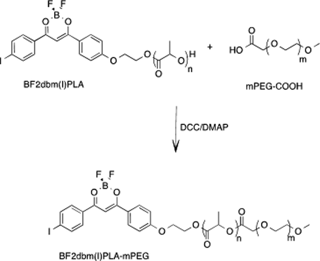
BF2dbm(I)PLA-mPEG Synthesis.
Figure 1.
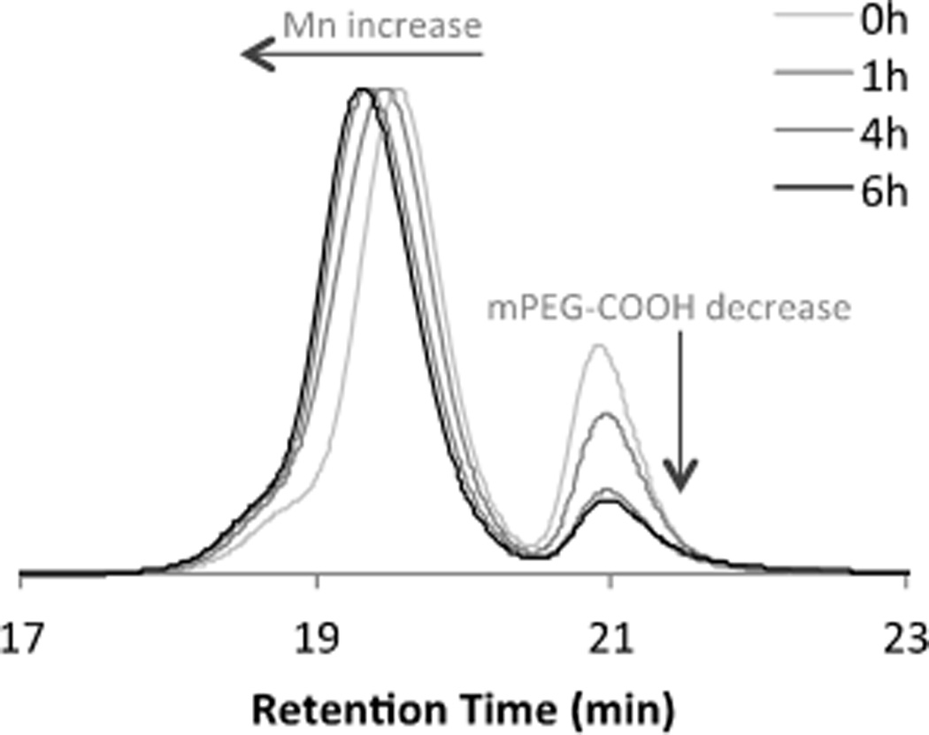
GPC trace of reaction progress for the coupling of BF2dbm(I)PLA with mPEG-COOH.
The final product was purified by filtration to remove dicyclohexylurea (DCU) and extraction with aqueous NH4Cl to remove base. Precipitation into −20 °C MeOH removed unreacted mPEG-COOH as confirmed by GPC. (Note: Water extraction doesn’t efficiently remove mPEG-COOH, even though PEG is soluble in water). Polymer coupling was confirmed by 1H NMR spectroscopy. Specifically, a singlet at 4.23 ppm (2H) is ascribed to the PLAOC(O)CH2OPEG linkage.
BF2dbm(I)PLA-mPEG Nanoparticles: Fabrication and Stability
Nanoparticles were fabricated by nanoprecipitation as previously described.[17] In brief, the dye-PLA-PEG polymer was dissolving polymer in DMF and added dropwise to stirred deionized water (dIH2O), followed by dialysis against the water to remove the organic solvent. Nanoparticles were filtered and characterized by dynamic light scattering (DLS), zeta potential ζ measurements, and optically. The particle hydrodynamic radius Rh is 47 nm with polydispersity PD = 0.23 and zeta potential ζ= −16 mV. The zeta potential significantly shifted comparing to PLA nanoparticles without PEG. For PLA alone, the ζ potential typically spans from −50 to −30 mV.[11] Optical measurements for dye-PLA-PEG NPs are in accord with previous BF2dbm(I) materials: UV/vis: λmax = 405 nm (ε= 51 000 M−1cm−1); fluorescence: λF = 450 nm, phosphorescence λP = 535 nm.
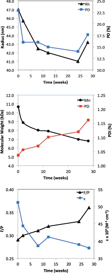
Boron BF2dbm(I)PLA-mPEG nanoparticle degradation was studied from the standpoint of nanoparticle structural stability, and dye and polymer degradation over the course of 28 weeks. Samples of the aqueous nanoparticle suspension obtained after fabrication were monitored over time. Generally, the hydrodynamic radius decreases from 47 to 42 nm reaching its minimal radius around 26 weeks after fabrication (Figure 2A). After 28 weeks the radius becomes larger again, perhaps due to nanoparticle structural degradation and increased porosity resulting in PLA-PEG swelling.[29–32] To test polymer properties over time, NP samples were freeze dried for GPC and UV/Vis analysis in CH2Cl2. According to GPC analysis, the polymer degrades due to ester bond hydrolysis.[30, 33, 34] The molecular weight decreases from 8.6 to 6.8 kDa with a PDI increase from 1.04 to 1.16 (Figure 2B). Dye degradation is evident by a decrease in the calculated extinction coefficient from 51 000 to 38 000 M−1 cm−1 (Figure 2C). The extinction coefficient was calculated using the measured MW at the given time point. Additionally, the fluorescence/phosphorescence intensity ratio for the total emission spectrum under nitrogen slightly increase (F/P = 0.29 – 0.33) in the first 24 weeks and then afterwards, during the next 4 weeks, increase further from 0.33 to 0.36, suggesting more rapid dye degradation corresponding to nanoparticle swelling (Figure 2C). In summary, after 24 weeks there is evidence of more significant BF2dbm(I)PLA-mPEG nanoparticle degradation. This may arise from swelling due to water diffusion into the matrix accelerating polymer and dye degradation. These results, with 74 % dye remaining after 196 days, shows improved stability of BF2dbm(I)OH dye in BF2dbm(I)PLA-mPEG nanoparticles compared to the previously published boron dye-PLLA/PDLA-PEG stereocomplexes[16] that showed 34 % dye remaining after 81 days.
Figure 2.
BF2dbm(I)PLA-mPEG nanoparticle degradation. (A) Nanoparticle hydrodynamic radius (Rh) and polydispersity (PD) versus time measured by DLS. (B) Polymer molecular weight (Mn) and polydispersity index (PDI ) versus time measured by GPC. (C) Dye degradation measured by UV/Vis and fluorescence spectroscopy (λex = 369 nm).
Oxygen Calibration and Tumor Imaging
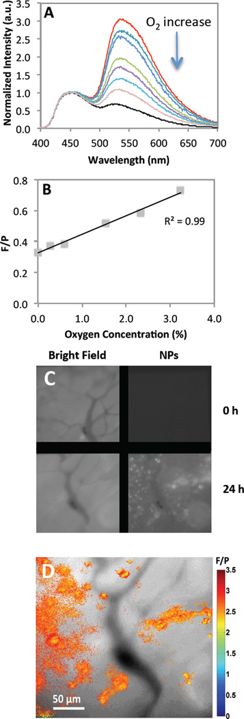
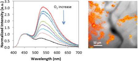
Optical properties of BF2dbm(I)PLA and PEGylated stereocomplexes were explored previously.[16, 17, 19, 35] This study shows that dual emissive optical properties also remain for the BF2dbm(I)PLA-mPEG conjugate after synthesis and nanofabrication. Fluorescence and phosphorescence are important for ratiometric oxygen sensing. Phosphorescence serves as the oxygen sensitive sensor and fluorescence as the standard, given it is typically invariant to changes in oxygen levels. Oxygen calibration was performed by recording emission spectra for PEGylated BNPs under different O2 concentrations (Figure 3 A and B). Similar to previous data,[17, 19] a linear F/P response was observed from 0–3% O2. In comparison to previous studies that employed a dorsal window chamber with tumor cells implanted between the skin and a glass coverslip for visualization, here in vivo imaging was performed by IV injection of BF2dbm(I)PLA-mPEG nanoparticles into mice (C57Bl/6 MMTV-PyMT strain) with spontaneous (i.e. genetic) mammary tumors. Once the tumors reached a certain size, mammary window chambers were surgically fitted as previously described.[36, 37] This approach has several advantages over the window chamber model in regard to providing a more accurate model of the disease state. Namely, it is an orthotopic tumor within the normal mammary stromal tissue, and it is a spontaneous tumor model meaning it develops in a more natural way. Figure 3 (C and D) shows images of the same tumor vasculature field before and after IV injection of the BF2dbm(I)PLA-mPEG nanoparticles. Slight rotation of images C and D relative to each other may be due to growth of the tumor between imaging time points, adjustment of the tumor tissue to the surgical implantation of the window, or some combination of the two. At 24 hours post-injection, NPs were evident in perivascular regions and F/P ratios show differences in oxygen levels within the tissue. Given that this in vivo model more accurately reflects spontaneous tumors that develop in a natural way, the accumulation of these nanoparticles into this cancer model is a significant and translatable achievement.
Figure 3.
Oxygen calibration. (A) Total emission spectra for different oxygen percentages (0–21% O2). (B) Fluorescence to phosphorescence intensity maxima ratio (F/P) versus oxygen concentration plot. (C) Mammary tumor window. Pictures shows images in bright field and optical imaging at 470 nm with BF2dbm(I)PLA-mPEG prior to injection and 24 hours after injection. (D) Combined F/P image from panel C with ratios indicating in vivo oxygen levels. (red: higher O2; blue: lower O2)
Conclusion
This study presents an efficient synthesis of a new dual-emissive BF2dbm(I)PLA-mPEG material and its use in the fabrication of nanoparticles with a dye-PLA core and mPEG shell. Covalent attachment of the dye to the polymer chain prevents dye leaching from the matrix and results in controllable optical properties. The in vivo uptake of nanoparticles into the spontaneous mammary tumor demonstrates the effectiveness of the PEG surface modification to stabilize particles in the blood during IV delivery. Once extravasated, the nanoparticles displayed a small range of oxygen-sensing ability. Thus, this preliminary proof-of-principle study confirms the capability of the reported nanoparticles to infiltrate tumor tissue in a spontaneous tumor and reveal information about the tumor microenvironment. Further dye, fabrication, targeting, and imaging method optimization, along with in vivo targeting and stability studies serve as the subjects of future research.
Acknowledgements
This research was supported by the National Cancer Institute of the National Institutes of Health (R01 CA167250). We gratefully acknowledge the University of Virginia Cancer Center for a fellowship (JSK) through the Farrow Fellowship Fund and the NCI Cancer Center Support Grant, P30 CA44579, and the North Carolina Biotechnology Center (2013-MRG-1111) for instrumentation support (GMP).
Contributor Information
Dr. Jelena Samonina-Kosicka, Department of Chemistry, University of Virginia, Charlottesville, VA 22904, USA
Dr. Douglas H. Weitzel, Department of Radiation Oncology, Duke University, Durham, NC 27710, USA
Christina L. Hofmann, Department of Radiation Oncology, Duke University, Durham, NC 27710, USA Department of Biomedical Engineering, Duke University, Durham, NC 27710, USA.
Dr. Hansford Hendargo, Department of Radiation Oncology, Duke University, Durham, NC 27710, USA
Dr. Gabi Hanna, Department of Radiation Oncology, Duke University, Durham, NC 27710, USA
Mark W. Dewhirst, Department of Radiation Oncology, Duke University, Durham, NC 27710, USA Department of Biomedical Engineering, Duke University, Durham, NC 27710, USA.
Gregory M. Palmer, Department of Radiation Oncology, Duke University, Durham, NC 27710, USA
Cassandra L. Fraser, Email: fraser@virginia.edu, Department of Chemistry, University of Virginia, Charlottesville, VA 22904, USA; Department of Biomedical Engineering, University of Virginia, Charlottesville, VA 22908.
References
- 1.Min Y, Li J, Liu F, Padmanabhan P, Yeow E, Xing B. Nanomaterials. 2014;4:129–154. doi: 10.3390/nano4010129. [DOI] [PMC free article] [PubMed] [Google Scholar]
- 2.Sen T, Bruce IJ. Sci Rep. 2012;2:564. doi: 10.1038/srep00564. [DOI] [PMC free article] [PubMed] [Google Scholar]
- 3.Holzinger M, Le Goff A, Cosnier S. Front. Chem. 2014;2:63. doi: 10.3389/fchem.2014.00063. [DOI] [PMC free article] [PubMed] [Google Scholar]
- 4.Kolate A, Baradia D, Patil S, Vhora I, Kore G, Misra A. J. Control. Release. 2014;192:67–81. doi: 10.1016/j.jconrel.2014.06.046. [DOI] [PubMed] [Google Scholar]
- 5.Harris JM, Chess RB. Nat. Rev. Drug. Discov. 2003;2:214–221. doi: 10.1038/nrd1033. [DOI] [PubMed] [Google Scholar]
- 6.Park K, Lee S, Kang E, Kim K, Choi K, Kwon IC. Adv. Funct. Mater. 2009;19:1553–1566. [Google Scholar]
- 7.Lammers T, Kiessling F, Hennink WE, Storm G. J. Control. Release. 2012;161:175–187. doi: 10.1016/j.jconrel.2011.09.063. [DOI] [PubMed] [Google Scholar]
- 8.Cho K, Wang X, Nie S, Chen ZG, Shin DM. Clin. Cancer Res. 2008;14:1310–1316. doi: 10.1158/1078-0432.CCR-07-1441. [DOI] [PubMed] [Google Scholar]
- 9.Markovsky E, Baabur-Cohen H, Eldar-Boock A, Omer L, Tiram G, Ferber S, Ofek P, Polyak D, Scomparin A, Satchi-Fainaro R. J. Control. Release. 2012;161:446–460. doi: 10.1016/j.jconrel.2011.12.021. [DOI] [PubMed] [Google Scholar]
- 10.Yue ZG, You ZX, Yang QZ, Lv PP, Yue H, Wang B, Ni DZ, Su ZG, Wei W, Ma GH. J. Mater. Chem. B. 2013;1:3239–3247. doi: 10.1039/c3tb20406e. [DOI] [PubMed] [Google Scholar]
- 11.Riley T, Govender T, Stolnik S, Xiong CD, Garnett MC, Illum L, Davis SS. Colloids Surf., B. 1999;16:147–159. [Google Scholar]
- 12.Huang YY, Chung TW, Tzeng TW. Int. J. Pharm. 1997;156:9–15. doi: 10.1016/s0378-5173(99)00060-5. [DOI] [PubMed] [Google Scholar]
- 13.Heald CR, Stolnik S, De Matteis C, Garnett MC, Illum L, Davis SS, Leermakers FAM. Colloids Surf., A. 2003;212:57–64. [Google Scholar]
- 14.Dong Y, Feng SS. Biomaterials. 2004;25:2843–2849. doi: 10.1016/j.biomaterials.2003.09.055. [DOI] [PubMed] [Google Scholar]
- 15.Govender T, Riley T, Ehtezazi T, Garnett MC, Stolnik S, Illum L, Davis SS. Int. J. Pharm. 2000;199:95–110. doi: 10.1016/s0378-5173(00)00375-6. [DOI] [PubMed] [Google Scholar]
- 16.Kersey FR, Zhang G, Palmer GM, Dewhirst MW, Fraser CL. ACS Nano. 2010;4:4989–4996. doi: 10.1021/nn901873t. [DOI] [PMC free article] [PubMed] [Google Scholar]
- 17.Pfister A, Zhang G, Zareno J, Horwitz AF, Fraser CL. ACS Nano. 2008;2:1252–1258. doi: 10.1021/nn7003525. [DOI] [PMC free article] [PubMed] [Google Scholar]
- 18.Zhang G, Chen J, Payne SJ, Kooi SE, Demas JN, Fraser CL. J. Am. Chem. Soc. 2007;129:8942–8943. doi: 10.1021/ja0720255. [DOI] [PubMed] [Google Scholar]
- 19.Zhang G, Palmer GM, Dewhirst MW, Fraser CL. Nat. Mater. 2009;8:747–751. doi: 10.1038/nmat2509. [DOI] [PMC free article] [PubMed] [Google Scholar]
- 20.Heald CR, Stolnik S, Kujawinski KS, De Matteis C, Garnett MC, Illum L, Davis SS, Purkiss SC, Barlow RJ, Gellert PR. Langmuir. 2002;18:3669–3675. [Google Scholar]
- 21.Zhang G, Palmer GM, Dewhirst MW, Fraser CL. Nat. Mater. 2009;8:747–751. doi: 10.1038/nmat2509. [DOI] [PMC free article] [PubMed] [Google Scholar]
- 22.Williams DBG, Lawton M. J. Org. Chem. 2010;75:8351–8354. doi: 10.1021/jo101589h. [DOI] [PubMed] [Google Scholar]
- 23.Shan S, Sorg B, Dewhirst MW. Microvasc. Res. 2003;65:109–117. doi: 10.1016/s0026-2862(02)00017-1. [DOI] [PubMed] [Google Scholar]
- 24.Kouros-Mehr H, Bechis SK, Slorach EM, Littlepage LE, Egeblad M, Ewald AJ, Pai S-Y, Ho IC, Werb Z. Cancer Cell. 2008;13:141–152. doi: 10.1016/j.ccr.2008.01.011. [DOI] [PMC free article] [PubMed] [Google Scholar]
- 25.Palmer G, Fontanella A, Shan S, Dewhirst M. High-Resolution In Vivo Imaging of Fluorescent Proteins Using Window Chamber Models. In: Hoffman RM, editor. In Vivo Cellular Imaging Using Fluorescent Proteins. Humana Press; 2012. pp. 31–50. [DOI] [PMC free article] [PubMed] [Google Scholar]
- 26.Li F, Li S, El Ghzaoui A, Nouailhas H, Zhuo R. Langmuir. 2007;23:2778–2783. doi: 10.1021/la0629025. [DOI] [PubMed] [Google Scholar]
- 27.Haslam E. Tetrahedron. 1980;36:2409–2433. [Google Scholar]
- 28.Neises B, Steglich W. Angew. Chem., Int. Ed. 1978;17:522–524. [Google Scholar]
- 29.Hamidi M, Azadi A, Rafiei P. Adv. Drug Deliv. Rev. 2008;60:1638–1649. doi: 10.1016/j.addr.2008.08.002. [DOI] [PubMed] [Google Scholar]
- 30.Metters AT, Anseth KS, Bowman CN. Polymer. 2000;41:3993–4004. [Google Scholar]
- 31.Wang D, Hill DJT, Peng H, Symons A, Varanasi S, Whittaker AK, Rasoul F. Macromol. Symp. 2010;296:233–237. [Google Scholar]
- 32.Hiemstra C, Zhong Z, Dijkstra P, Feijen J. Hydrogels. Springer Milan; 2009. Stereocomplexed PEG-PLA Hydrogels; pp. 53–65. [Google Scholar]
- 33.Grizzi I, Garreau H, Li S, Vert M. Biomaterials. 1995;16:305–311. doi: 10.1016/0142-9612(95)93258-f. [DOI] [PubMed] [Google Scholar]
- 34.Pistner H, Gutwald R, Ordung R, Reuther J, Muhling J. Biomaterials. 1993;14:671–677. doi: 10.1016/0142-9612(93)90066-b. [DOI] [PubMed] [Google Scholar]
- 35.Samonina-Kosicka J, DeRosa CA, Morris WA, Fan Z, Fraser CL. Macromolecules. 2014;47:3736–3746. doi: 10.1021/ma5006606. [DOI] [PMC free article] [PubMed] [Google Scholar]
- 36.Palmer GM, Fontanella AN, Shan S, Hanna G, Zhang G, Fraser CL, Dewhirst MW. Nat. Protocols. 2011;6:1355–1366. doi: 10.1038/nprot.2011.349. [DOI] [PMC free article] [PubMed] [Google Scholar]
- 37.Huang Q, Shan S, Braun RD, Lanzen J, Anyrhambatla G, Kong G, Borelli M, Corry P, Dewhirst MW, Li CY. Nat. Biotechnol. 1999;17:1033–1035. doi: 10.1038/13736. [DOI] [PubMed] [Google Scholar]


