Abstract
In high-field magnetic resonance imaging, the radio frequency wavelength within the human body is comparable to anatomical dimensions, resulting in B1 inhomogeneity and nonuniform sensitivity patterns. Thus, this relatively short wavelength presents engineering challenges for RF coil design. In this study, a bilateral breast coil for 1H imaging at 7 T was designed and constructed using forced-current excitation. By forcing equal current through the coil elements, we reduce the effects of coupling between the elements to simplify tuning and to ensure a uniform field across both breasts. To combine the benefits of the higher power efficiency of a unilateral coil with the bilateral coverage of a bilateral coil, a switching circuit was implemented to allow the coil to be reconfigured for imaging the left, right, or both breasts.
Index Terms: 7T, breast coils, dual mode, forced-current excitation (FCE), high field MRI
Introduction
In recent years, efforts have been made to translate existing MR technologies to 7 T in order to capitalize on the improved sensitivity and signal-to-noise ratio (SNR) [1]–[5]. Several clinical 7 T breast studies have demonstrated the feasibility and the advantage of utilizing high field [3], [6]–[11]. Operating at high fields, however, presents a number of engineering challenges. Transmitting at a higher Larmor frequency creates a shorter radio frequency (RF) wavelength in the body, often resulting in B1 inhomogeneity and nonuniform sensitivity [12]–[14]. When designing high field coils with multiple elements, the shorter RF wavelength also causes more complex element-to-element interactions, complicating coil tuning. A number of research groups have employed parallel RF transmission to address the high-field inhomogeneity problem [15]–[19]. This method utilizes multiple transmit channels, individually controlling the current on each coil element, to achieve a uniform excitation. However, the high channel count needed to implement this technique is often expensive and available at a few research sites only; hence, single-channel techniques are still needed. In the past, our group has successfully applied the forced-current excitation (FCE) technique on high field multielement coil designs to obtain some of the advantages of a two-channel transmitter at much lower complexity and cost. The FCE technique exploits transmission line properties to ensure that equal currents are delivered to the feedpoints of all elements [20]. This approach has been shown to mitigate inhomogeneity arising from the asymmetric coil loading encountered in breast imaging [21].
In clinical practice, a bilateral study is preferred as it simplifies planning and interpretation of the results [11], [22]–[24]. Comparing images from both breasts can reduce false positive detection in dynamic contrast enhancement (DCE)-MRI. Additionally, studies indicate that in women recently diagnosed with unilateral breast cancer, additional cancer lesions are sometimes detected in the contralateral breast [25]. Several 7T breast studies have indicated a need for bilateral coil design [8], [11]. On the other hand, in some applications, e.g., proton decoupling in second-nuclei applications, a unilateral coil may be preferred, since it enables judicious use of the available total proton decoupling power in a single breast [26]–[28]. Our group has reported a unilateral, quadrature FCE breast coil previously [21]. Here, we describe the extension of the unilateral coil to a new switched-mode coil. The new coil can be configured for either bilateral operation or unilateral operation for either breast. By extending the FCE approach to both sides of the array, the mutual impedance between the left and right arrays is also mitigated, eliminating potential asymmetries caused by mode splitting. The switched-mode coil was evaluated on the bench and through MRI experiments in its different configurations. Efficiency comparison was made on bench with the previously reported unilateral coil.
II. Materials and Methods
A. Coil Design
In designing the switched-mode coil, we initially duplicated a previous unilateral coil construct [21] and added a switching network to enable selectable bilateral and unilateral (left/right) operation. The switching network was designed to enforce the FCE condition in all modes. All coil conductors were etched from copper-clad FR-4 PCB.
Each quadrature unilateral coil consisted of a Helmholtz pair and a saddle pair, as previously described in [21]. In brief, the two identical loops comprising the Helmholtz pair had 16 cm i.d. and 17.2 cm o.d. and were coaxially separated by 8 cm in the vertical y-direction. Each element was segmented by eleven 10 pF capacitors. A concentric coplanar shield surrounded each loop, with 18 cm i.d. and 18.7 cm o.d.; the addition of coplanar shields has been shown to reduce E-field radiation from the coil [21]. To prevent eddy currents, each shield was segmented in two locations by 1800 pF capacitors. The saddle pair coils were affixed on opposite sides of a 15.2 cm i.d. acrylic tube and centered inside the Helmholtz pairs. The elements were rectangular with inner measurements (when flat) of 15.3 cm width and 8.1 cm height and outer measurements of 16.5 cm width and 9.4 cm height. When mounted at radius 7.6 cm, each saddle produced an angular aperture of 120°. Analogous to the coplanar shields on the Helmholtz elements, rectangular shielding conductors of 0.4 cm width were spaced 0.5 cm outside of the saddles. Each coil element was segmented by eleven 12 pF capacitors, and the shield was segmented at two locations by 1800 pF capacitors.
To enable bilateral operation, the unilateral coil was duplicated and the two coils were spaced 19.2 cm center-to-center in the x direction. In this paper, we define the term “left coil” as the coil used to image the left breast of a patient (−x), and “right coil” as the coil to image the right breast (+x). Photographs of the coil are shown in Fig. 1.
Fig. 1.
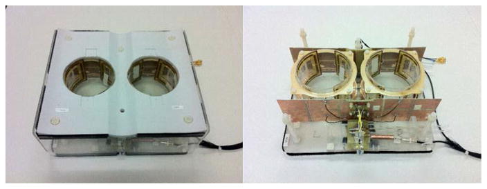
Switchable bilateral quadrature coil closed in a housing (left) and with covers removed (right) forms.
The close proximity of the two quadrature coils raised concerns of potential B1 field cancellation in the bilateral configuration. Two feeding schemes were available: with the B1 field having the same direction [see Fig. 2(a)]; with the B1 field having the opposite direction [see Fig. 2(b)]. The first arrangement provided better SNR in simulations and was chosen for the final design.
Fig. 2.

Possible quadrature B1 field arrangements (a) with the B1 fields in the same direction. (b) with the B1 fields in opposite directions. The arrangement on the left was chosen based on numerical simulations.
B. FCE and Mode Switching
The theory behind the FCE method has been presented elsewhere [20]. In brief, in a single-channel multielement array design, the elements are connected to a common voltage point (CVP) through quarter-wavelength transmission lines. The resulting current at the feed point of each element is equal despite differences in loading and mutual impedance between elements [20]. In this coil, all four elements in the two Helmholtz pairs were connected to one CVP through quarter-wavelength segments of semirigid coaxial cable, and all four elements in the two saddle pairs were connected to a second CVP using the same method.
The circuit boards for the CVP included p-i-n diode switching networks allowing unilateral/bilateral mode selection. Four operating modes were possible: Both coils activated (bilateral mode, mode 1); Left coil activated with right coil detuned (mode 2); Right coil activated with left coil detuned (mode 3); Both coils detuned (mode 4). Modes 1–3 were utilized for transmit/receive configurations, and mode 4 was included for potential future use with receive array inserts. To control mode switching of the two coils, we assembled a power supply switching device to provide two dc supply signals which can be switched between +12 and −12 V; positive polarity activates the corresponding coil, whereas negative polarity effectively disconnects and detunes the coil.
A simplified schematic of the switching circuit with coil connections is presented in Fig. 3. RF chokes on the dc bias lines and current limiting resistors are omitted for clarity.
Fig. 3.
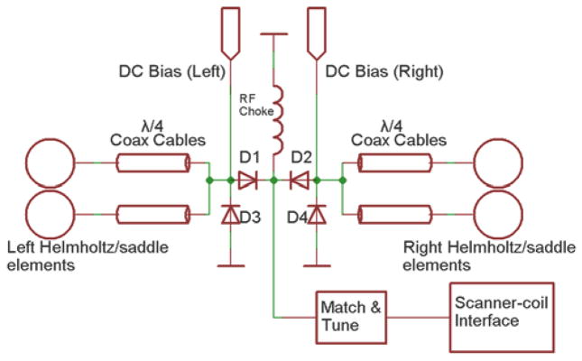
Schematic of switching network for operating mode control of the Helmholtz/saddle pairs. The same dc signals for switching are routed to the Helmholtz and saddle switching network.
The path for the RF is determined by the status of p-i-n diodes D1 and D2 (UM9415, Microsemi, Lowell, MA, USA). A +12/−12V signal forward/reverse biases D1 or D2, which connects/disconnects the corresponding coil elements to/from the RF chain. In unilateral mode, it is necessary to detune the nonactive coil. The FCE implementation provides a straightforward method to detune a coil: when D1 or D2 is reverse biased, D3 or D4 is forward biased by the same dc signal, essentially creating a short-circuit at the CVP. According to transmission line theory, the quarter-wavelength coaxial lines transform the short-circuit to an open-circuit at the feed of the coil elements, consequently detuning those elements. When D1 or D2 is forward biased, D3 or D4 is reverse biased by the same dc signal and does not affect the RF chain. The switching network is followed by a single match/tune board after which the matched coil is connected directly to one port of the scanner quadrature coil interface box, which provides the RF preamplifier and transmit/receive switching. The apparatus and signal paths shown in Fig. 3 are duplicated for the other set of coils (Helmholtz or saddles).
To summarize, by combining the FCE method and the diode switching network, equal current is forced at the coil elements within the same coil (modes 1–3), as well as the left and right coils (mode 1). In modes 2 and 3, the unused coil is detuned.
C. Shielding
Because the quarter-wavelength coaxial lines connecting the left and right elements to the CVP boards share a common ground at the boards, upon implementing the bilateral design the shields of these cables were found to support additional half-wavelength dipole modes, which degraded performance and affected left-right symmetry. These cable modes were largely mitigated by placing two identical parallel copper shields in the transverse plane, superior and inferior to the coils, spaced 1 cm from the outer conductors. Each shield has dimensions of 40.7 cm (x) × 10.3 cm (y). The shields were segmented along the x- and y-directions to mitigate the effect of eddy currents, with four evenly spaced y-directed cuts, and one central x-directed cut which skips the middle area where the switching circuit boards were mounted.
D. Electromagnetic Modeling
FDTD simulation software (Xfdtd 7.4, Remcom, State College, PA, USA) was used to perform electromagnetic simulation to calculate B1 + and specific absorption rate (SAR) generated by the coil. The phantom previously utilized in [21] was used for comparison purposes. This phantom included a cylinder consisting of breast fat material (σ = 0.033 S/m and εr = 5.54) and a rectangular block consisting muscle material (σ = 0.77 S/m and εr = 58.2). The dielectric properties of the different materials were obtained from [29]. The coil was simulated in modes 1–3. For each mode, the active coil elements were fed with high impedance (1000 Ω), 1-A steady-state current sources to simulate the FCE drive condition. 0° and 90° phase offsets were added to the Helmholtz and saddle feeds, respectively, to create quadrature excitation. The nonactive coil elements in modes 2–3 are left open-circuited at their feed points.
E. Coil Testing—Bench Measurements
The switched-mode coil B1 + efficiency was initially evaluated on the bench in all three modes. A prototype Helmholtz pair bilateral coil was also tested on bench to analyze the effect of FCE on tuning and homogeneity.
1) FCE Versus non-FCE Performance
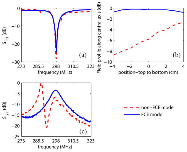
When the switched-mode coil operates in a bilateral mode, the coupling between the two closely spaced quadrature coils creates multiple modes with different relative current amplitudes and phases in the elements. This complicates the coil tuning and affects the field homogeneity. To evaluate the impact of using the FCE method in such a scenario, a prototype Helmholtz pair bilateral coil with slightly smaller dimensions (14.8 cm i.d. for each coil) was tested on the bench. FCE versus non-FCE performance was evaluated. In the non-FCE case, 3λ/8 coax cables, instead of λ/4 were used to excite the Helmholtz pair elements after the CVP. The following comparison data were collected: 1) S11 response of the bilateral coil over a 50 MHz span centered at 298 MHz, 2) Field profiles at 298 MHz along the central axis in the left coil using a shielded pickup loop, and 3) Field strength measured as the S21 response between the coil and the same pickup loop located at +1 cm on the central axis of the left coil (0 cm represents the isocenter of the coil, and positive values represent positions toward the bottom of the coil), over a 50 MHz span centered at 298 MHz.
2) Switched Mode Coil-efficiency Comparison of the Three Modes
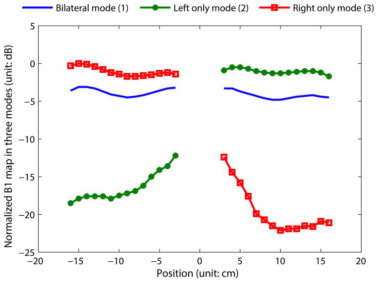
As discussed above, one potential advantage of allowing unilateral operation on the switched-mode coil is higher power efficiency over the bilateral mode. The incoming RF signal, as represented in Fig. 3, should divide evenly into the two coils in bilateral mode owing to the symmetric circuit structure. When switching from bilateral mode to unilateral mode, the input power is directed into the active coil and a 3 dB higher power efficiency is expected. To evaluate the coil efficiency in modes 1–3 (bilateral, unilateral-right only, unilateral-left only), the Helmholtz pairs and saddle pairs were tuned to 50 Ω at their feed-points and excited in quadrature mode. One-dimensional field profiles were measured along the x-axis through both coils using a measurement system dedicated for RF coil characterization [30] and a quadrature shielded pickup loop. The measurements were repeated for modes 1–3 and the B1 + profiles were plotted together to compare efficiency. To fully evaluate the coil performance under potential coupling between the multiple elements, the coil was tested unloaded where the highest quality factor was achieved. Additionally, the insertion loss of the switching circuit was measured to evaluate the effect of the diodes in the RF path. The impact of such loss on the coil was then evaluated on bench by comparing the efficiency of the coil in unilateral mode to the purely unilateral coil described earlier [21].
F. Coil Testing—MRI Experiments
The switched-mode coil performance was evaluated on a whole-body 7 T scanner (Achieva, Philips Medical Systems).
1) Phantom Imaging
The phantom was constructed out of a container shaped as a tapered cylinder, 13.4 cm diameter at the top decreasing to 10.8 cm diameter at the bottom. Two such containers were filled with canola oil to mimic lipid properties of the breast and were placed inside the two quadrature coils, with the top of the phantom container at 1 cm above the top Helmholtz loop.
Phantom images were acquired in coil modes 1–3. The coil efficiencies of modes 1–3 were compared by recording the peak transmit drive scale (DS) required to achieve a 90° tip angle over a rectangular region in the center of the phantom.
2) In Vivo Breast Imaging
To test coil performance two volunteers with different breast cup size were scanned under an Internal Review Board approved protocol and after signing an informed consent. In vivo bilateral coverage and fat suppression uniformity were tested by acquiring coronal 3-D T1-weighted fast gradient echo (THRIVE) images with and without fat suppression. Additional in vivo imaging parameters were as follows: FOV 370 mm × 285 mm × 150 mm (RL × FH × AP), resolution 1 mm × 1 mm × 1 mm (overcontiguous), TR/TE/FA: 4.0 ms/1.6 ms/8°, SPAIR with TI = 150 ms (for fat saturation), partial Fourier acquisition of 0.7 (halfscan) in the first phase encoding direction, for a total scan time of 1:22 min (no fat saturation) and 3:44 min (with fat saturation). The original coronal images were also reconstructed in the axial plane as 1-mm projections. Coil excitation homogeneity was evaluated using B1 mapping with a dual TR acquisition [31] with nominal flip angle of 50°, TR1/TR2 = 35/140 ms, and resolution 3 mm × 3 mm × 2 mm.
III. Results and Discussion
A. Electromagnetic Modeling
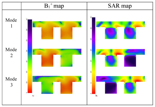
The 3-D model of the coil and breast phantom is shown in Fig. 4. B1 + field maps and 10-g averaged SAR maps at the Larmor frequency (298.03 MHz at 7 T MRI) were obtained in the central axial plane in modes 1–3, and are shown in Table I. All modes had 1 W total power applied.
Fig. 4.
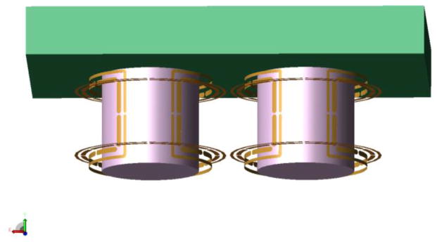
Coil and phantom model. The shields are not shown for clarity.
TABLE I.
Central Axial Plane B1 + and 10-g Averaged SAR Maps in Modes 1–3
|
The results were scaled to 1 W total input power to the coil. 0 dB corresponds to 1.97 μ T and 0.99 W/kg in the B1 + and SAR maps, respectively.
As expected, higher B1 +, as well as SAR are generated in the active coil in unilateral mode as compared to bilateral mode for the same amount of input power. The B1 + in the nonactive coil in unilateral mode is suppressed by approximately 20 dB, as compared to the active coil. In all three modes, highest SAR is observed in the chest wall.
In unilateral mode, the unused coil is detuned and does not produce significant SAR; therefore, the B1 +/sqrt(total SAR) is higher in unilateral mode. This is useful in cases where the peak power or total SAR is limited. Accordingly, the SNR is also higher in unilateral mode, by reciprocity. Of course, since the left and right coils are identical, B1 +/sqrt(maximum SAR) was found to be very close (within 0.3 dB) in the active coil for all three modes. Thus, the mode does not change peak SAR performance. Therefore, enabling the unilateral mode may be advantageous in applications like proton decoupling if the peak available power is limited.
B. Coil Testing-Bench Measurements
1) FCE Versus non-FCE Performance
The FCE versus non-FCE performance was evaluated on the prototype Helmholtz pair bilateral coil. In both cases, the coil was tuned to 50 Ω at 298 MHz—resonance frequency at 7 T. The S11 response of the bilateral coil, the field profile along the central axis of the left coil at 298 MHz measured with a pickup loop, and the S21 between the coil and the pickup loop located at +1 cm on the central axis of the left coil, was recorded and compared for the two cases, as shown in Fig. 5.
Fig. 5.
Comparison between FCE mode and non-FCE mode. (a) S11 of the bilateral coil over a 50 MHz span, good matching was achieved at the coil port for both cases. (b) Normalized field profiles along the central axis of the left coil at 298 MHz, presented in decibels. In non-FCE mode the coil exhibits field inhomogeneity even when unloaded due to capacitor tolerances in the elements, both of which are connected to a common tune capacitor. When operated in FCE mode, the coil shows much better homogeneity. (c) Normalized S21 over a 50 MHz span at +1 cm on the central axis of the left coil. When operated in FCE mode, the desired mode (equal currents) appears at 298 MHz, giving a uniform field plot. When operated in non-FCE mode, the coil shows a more complex mode structure, and does not provide equal currents in the coil elements resulting in an inhomogeneous field.
In the FCE case, presented with blue curves and symbols, the coil behaves well despite the presence of four closely coupled elements: the S11 response shows a single mode in the span (a), the field profile is uniform indicative of equal currents in the elements (b), and the response peaks at the desired frequency (c). In the non-FCE case, the S11 response indicates the presence of multiple modes. Since the coil elements are not tuned independently and equal currents are not enforced, the resulting field profile (b) is highly inhomogeneous. The 3λ/8 feedlines (non-FCE condition) did not ensure equal currents, and indeed represented a “free” voltage excitation case in which the mutual impedance between elements must be accounted for to ensure operation in the proper mode [32]. In this case, that would require more degrees of freedom in tuning the coil than just a single matching network. This behavior is reflected in the rapidly varying field intensity with frequency in the non-FCE mode shown in Fig. 5(c).
2) Switched-Mode Coil-Efficiency Comparison of the Three Modes
The B1 + profiles of the switched-mode coil operating in modes 1–3 are plotted in Fig. 6. In unilateral mode (modes 2 and 3), the inactive coil was detuned. Since the two coils were closely spaced, the active coil has some sensitivity over the region within the detuned coil. This detected residual signal decreases toward the outer edge of the detuned coil and is primarily due to the natural sensitivity of the “on” coil, as shown below.
Fig. 6.
One-dimensional B1 + profiles across the ROI, along x-direction. The data measured in modes 1–3 are normalized to a global maximum and plotted together for comparison. When operated in unilateral mode, the active coil has around 3 dB higher sensitivity than when operated in bilateral mode. The nonactive coil has much lower sensitivity (9–20 dB lower than the active coil), which indicates successful detuning.
When switching from bilateral mode to unilateral mode, a 1.8–3.5 dB increase in RF power sensitivity was observed within the activated coil, with an increase of approximately 3 dB at the central region of the coil. Enforcing equal currents in the left and right coils results in symmetric fields despite high mutual impedance between the two coils and slight differences in components and the fabrication process. When operated in unilateral mode, the nonactive coil has 9–20 dB lower sensitivity than the active coil.
The insertion loss of the switching circuit was found to be 0.6 dB at 298 MHz, which is mainly caused by the series diodes. The power efficiency of the switched-mode coil in unilateral mode was measured to be 0.6 dB (13%) worse than that of the purely unilateral coil, which does not have the diode switching circuit.
C. Coil Testing-MRI Experiments
1) Phantom Imaging
Phantom images were acquired with the switched-mode coil. All images were acquired with a same set of scan parameters and the same phantoms. Fig. 7(a)–(c) are the images acquired with the switched-mode coil in the three modes (for a discussion of the in vivo images, please see the next section). When the switched-mode coil operates in unilateral mode (modes 2–3), the residual signal received by the detuned coil was predominantly suppressed, with the maximum signal in that region only 10% of that in the active coil. This is consistent with the bench results in Fig. 6. It is evident that the inactive coil in the switched mode coil is effectively detuned by the switching network.
Fig. 7.
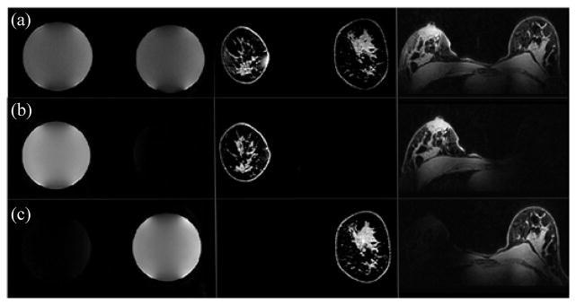
Coil mode performance as illustrated by phantom and in vivo imaging: (a, top row) switched-mode coil: bilateral mode. (b) Switched-mode coil: right only mode. (c) Switched-mode: left only mode. Original in vivo acquisition (coronal) and reconstructed (axial) images are shown in the middle and right columns, respectively. Symmetric performance is observed in the bilateral mode, while excellent signal localization is seen in the unilateral modes.
On the 7-T Philips Achieva scanner, the output voltage of the power amplifier is linearly proportional to the transmitter drive scale, so the output power is proportional to the square of the drive scale. The DS for a 90° tip angle using the switched-mode coil was recorded during the transmit gain calibration phase in modes 1–3 is shown in Table II, along with relative output power of each case, scaled to 0 dB for the bilateral mode 1. The coil was also compared on the bench by measuring the S21 between the coil and a pickup loop in the center of the active coil in all modes. In each case, the coil was tuned to 50 Ω, and the power required to obtain the same field strength at the pickup loop was recorded and scaled to the result of mode 1. The bench result is consistent with the MR measurements.
TABLE II.
Transmitter (TX) Drive Scale (DS), Transmitter Relative Output Power, and Bench Measurement of the Three Modes
| Mode | TX DS | TX Relative Output Power | Bench |
|---|---|---|---|
| Bilateral-Mode 1 | 0.512 | 0 dB | 0 dB |
| Left only-Mode 2 | 0.352 | −3.3 dB | −3.5 dB |
| Right only-Mode 3 | 0.334 | −3.7 dB | −3.2 dB |
The results in Table II demonstrate that the switched-mode coil, when in unilateral mode, is approximately twice as efficient as its bilateral mode, which may be useful for certain applications, such as chemical exchange saturation transfer or proton decoupling, that requires high-transmit field intensity.
2) In Vivo Breast Imaging
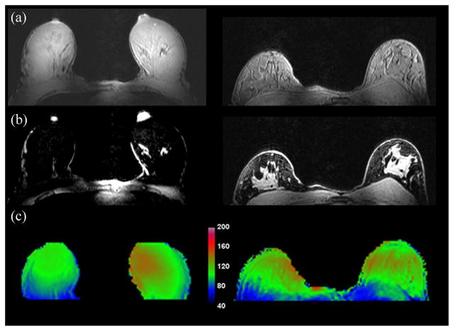
Similar to the phantom experiments, in vivo images were acquired with the switched-mode coil in all three modes (see Fig. 7). Original in vivo acquisition (coronal) and reconstructed (axial) fat-suppressed images are shown in the middle and right columns, respectively. Excellent signal localization is seen in the unilateral modes, with less than 10% of the signal being excited in the nonenabled coil. Fig. 8 shows in vivo images in bilateral mode with and without fat suppression (top and middle rows, respectively). While the volunteers presented different breast cup sizes (left: C/D, right: A/B), the bilateral mode produced uniform excitation, as seen from the images and from the B1 + field maps (bottom row). The volunteer in vivo images demonstrate good bilateral coverage and uniform fat suppression. Good coverage of the chest wall and the axilla is also seen.
Fig. 8.
(a) and (b) In vivo 3-D THRIVE images (first two rows, with and without fat suppression, respectively) in bilateral mode demonstrate coil performance for varying breast sizes. Good coverage of both breasts and the chest wall is seen, along with uniform fat suppression attesting to the transmission homogeneity of the coil. (c) Flip angle maps demonstrate sufficient homogeneous excitation over the bilateral FOV.
IV. Conclusion
At 7 T, FCE is one approach to overcome B1 inhomogeneity as demonstrated in a unilateral breast coil [21]. Since clinical breast imaging requires a bilateral coil, the FCE principle was extended to the operation of two unilateral coils simultaneously, or individually. A switched-mode coil operated at 7 T introduces significant challenges due to the high coupling between two closely spaced unilateral quadrature coils when operated simultaneously. This coupling will introduce additional unwanted modes, making it difficult to ensure operation in the desired mode and with the desired current distribution. In addition, it is desirable to have a coil that is relatively insensitive to the uneven and variable coil loading presented by the general population. By using the FCE method, the current at feed points of each coil element was forced to be equal within the same coil, as well as the left and right coils (when operated in bilateral mode). This addresses the complication in tuning a multielement coil and achieves better field homogeneity. The switched-mode performance was also evaluated. Bench measurements and MR experiments largely agreed and indicated that the switched-mode coil is around 3 dB more efficient in unilateral mode than bilateral mode. This advantage in power efficiency has the potential to facilitate high-power applications, such as proton-decoupled second-nuclei applications. In vivo breast imaging in the bilateral mode demonstrated good bilateral coverage and uniform fat suppression, which are both required for clinical research studies.
Acknowledgments
This work was supported by CPRIT under Grant RP100625 and under NIH Grant EB016394 and Grant EB015908.
Biographies
 Jiaming Cui (S’13) received the B.S. degree in electrical engineering from Shanghai Jiao Tong University, Shanghai, China, in 2011. He is currently working toward the Ph.D. degree in electrical engineering in Texas A&M University, TX, USA.
Mr. Cui is a Student Member of the International Society for Magnetic Resonance in Medicine.
 John C. Bosshard received the B.S. and Ph.D. degrees in electrical engineering from Texas A&M University, College Station, TX, USA, in 2006 and 2012, respectively.
He has a background in radio communications, working several summers at a family business. He spent the summer of 2007 working in the receive coil group in the magnetic resonance division of Siemens Medical Solutions, Erlangen, Germany, and is currently in a postdoctoral position with the Department of Electrical and Computer Engineering, Texas A&M University. His research interests include magnetic resonance systems hardware and parallel imaging.
 Joseph V. Rispoli (M’12) received the B.S. degree in electrical engineering from the University of Virginia, Charlottesville, VA, USA, in 2002.
He worked as the Development Engineer for Dell, Inc., from 2002 to 2010, and he is currently a Research Assistant and doctoral candidate in biomedical engineering at Texas A&M University, College Station, TX, USA.
 Ivan E. Dimitrov received the B.S. degree in physics from University of Oregon, Eugene, OR, USA, in 1994, and the Ph.D. degree in molecular biophysics and biochemistry from the University of Pennsylvania, Philadelphia, PA, USA, in 2000 on the topic of MRI and MRS of hyperpolarized noble gases.
He then spent a year as a postdoctoral in the lab of Alex Pines in UC Berkeley, working on polarization transfer techniques. From 2004, he joined Philips Medical Systems where he works to develop clinically relevant applications of MRI and MRI, with emphasis on ultrahigh-field breast imaging and spectroscopy, as well as advanced body applications. He contends that in vivo hyperpolarization will be commercially available within several short years.
 Sergey Cheshkov received the B.S. degree in physics from Sofia University, Sofia, Bulgaria, in 1995. He received the Ph.D. degree in physics from University of Texas at Austin, Austin, TX, USA, in 2001.
His main area of research was in advanced laser-plasma particle accelerators. Following several positions in high-tech industry, he joined UT Southwestern as a postdoc in MRI in 2004 and was promoted to Assistant Professor in 2006. He was co-PI and later PI for the MRS subcore of the UTSW Gulf War Neuro-imaging Project. His research interest include high-field MR spectroscopy (proton and multinuclear) and MRI with applications in breast cancer.
 Mary Preston McDougall (S’04–M’05) received the B.S. degree from Texas A&M University, College Station, TX, USA, in 1997, the M.S. degree from Johns Hopkins University, Baltimore, MD, USA, in 1999, and the Ph.D. degree from Texas A&M University in 2004, all in electrical engineering.
From 2004 to 2006, she was a Postdoctoral Research Assistant and then a Research Assistant Professor in the Department of Electrical and Computer Engineering at Texas A&M. In 2006, she joined the faculty of Biomedical Engineering at Texas A&M and is now an Associate Professor. She also holds a joint appointment in the Electrical and Computer Engineering Department. Her research interests include RF coil design for high field MRI and applications of dynamic and high-resolution magnetic resonance imaging and spectroscopy.
 Craig Malloy received the B.S. degree in chemistry from Stanford University, Stanford, CA, USA, and the M.D. degree from the University of California at San Francisco, San Francisco, CA, USA.
After further training in internal medicine, cardiology and biochemistry, he joined the faculty at the University of Texas Southwestern Medical Center in 1984. His research interests include the use of stable isotopes for analysis of metabolic pathways in human patients.
 Steven M. Wright (S’78–M’85–F’10) received the B.S., M.S., and Ph.D. degrees in electrical engineering from the University of Illinois, Urbana, IL, USA.
From 1984–1988, he was an Engineer/Scientist for MRI at Saint Francis Medical Center, Peoria, IL, USA. He joined the Faculty at Texas A&M University, College Station, TX, USA, in 1988, where he established the Magnetic Resonance Systems Lab. His research interests include development of instrumentation and techniques for magnetic resonance imaging and spectroscopy and in computational electromagnetics.
Dr. Wright is a Member of the IEEE Engineering in Medicine and Biology Society and is a Fellow of the International Society of Magnetic Resonance in Medicine and the American Institute for Medical and Biological Engineering.
Footnotes
Color versions of one or more of the figures in this paper are available online at http://ieeexplore.ieee.org.
Contributor Information
Jiaming Cui, Email: jm0828@tamu.edu, Texas A&M University, College Station, TX 77843 USA.
John C. Bosshard, Texas A&M University
Joseph V. Rispoli, Texas A&M University.
Ivan E. Dimitrov, University of Texas Southwestern Medical Center and also with Philips Medical Systems
Sergey Cheshkov, University of Texas Southwestern Medical Center.
Mary Preston McDougall, Texas A&M University.
Craig Malloy, University of Texas Southwestern Medical Center, and also with VA North Texas Health Care System.
Steven M. Wright, Texas A&M University.
References
- 1.Vaughan JT, et al. Whole-body imaging at 7T: Preliminary results. Magn Resonance Med. 2009;61(1):244–248. doi: 10.1002/mrm.21751. [DOI] [PMC free article] [PubMed] [Google Scholar]
- 2.Adriany G, et al. Transmit and receive transmission line arrays for 7 Tesla parallel imaging. Magn Resonance Med. 2005;53(2):434–445. doi: 10.1002/mrm.20321. [DOI] [PubMed] [Google Scholar]
- 3.Korteweg MA, et al. Feasibility of 7 Tesla breast magnetic resonance imaging determination of intrinsic sensitivity and high-resolution magnetic resonance imaging, diffusion-weighted imaging, and 1H-magnetic resonance spectroscopy of breast cancer patients receiving neoadjuvant therapy. Investigative Radiol. 2011;46(6):370–376. doi: 10.1097/RLI.0b013e31820df706. [DOI] [PubMed] [Google Scholar]
- 4.Kraff O, et al. MRI at 7 tesla and above: Demonstrated and potential capabilities. J Magn Resonance Imag. 2014;41:13–33. doi: 10.1002/jmri.24573. [DOI] [PubMed] [Google Scholar]
- 5.Wu B, et al. Shielded microstrip array for 7T human MR imaging. IEEE Trans Med Imag. 2010 Jan;29(1):179–184. doi: 10.1109/TMI.2009.2033597. [DOI] [PMC free article] [PubMed] [Google Scholar]
- 6.Dimitrov IE, et al. In vivo determination of human breast fat composition by 1H magnetic resonance spectroscopy at 7 T. Magn Resonance Med. 2012;67(1):20–26. doi: 10.1002/mrm.22993. [DOI] [PMC free article] [PubMed] [Google Scholar]
- 7.Stehouwer BL, et al. 7T versus 3T contrast-enhanced breast magnetic resonance imaging of invasive ductulolobular carcinoma: First clinical experience. Magn Resonance Imag. 2013;31(4):613–617. doi: 10.1016/j.mri.2012.09.005. [DOI] [PubMed] [Google Scholar]
- 8.Stehouwer BL, et al. Dynamic contrast-enhanced and ultra-high-resolution breast MRI at 7.0 Tesla. Eur Radiol. 2013;23(11):2961–2968. doi: 10.1007/s00330-013-2985-9. [DOI] [PubMed] [Google Scholar]
- 9.Wijnen JP, et al. Quantitative 31P magnetic resonance spectroscopy of the human breast at 7 T. Magn Resonance Med. 2012;68(2):339–348. doi: 10.1002/mrm.23249. [DOI] [PubMed] [Google Scholar]
- 10.Klomp DW, et al. 31P MRSI and 1H MRS at 7 T: Initial results in human breast cancer. NMR Biomed. 2011;24(10):1337–1342. doi: 10.1002/nbm.1696. [DOI] [PubMed] [Google Scholar]
- 11.Pinker K, et al. Clinical application of bilateral high temporal and spatial resolution dynamic contrast-enhanced magnetic resonance imaging of the breast at 7 T. Eur Radiol. 2013;24:1–8. doi: 10.1007/s00330-013-3075-8. [DOI] [PubMed] [Google Scholar]
- 12.Mao W, et al. Exploring the limits of RF shimming for high-field MRI of the human head. Magn Resonance Med. 2006;56(4):918–922. doi: 10.1002/mrm.21013. [DOI] [PMC free article] [PubMed] [Google Scholar]
- 13.Schick F. Whole-body MRI at high field: technical limits and clinical potential. Eur Radiol. 2005;15(5):946–959. doi: 10.1007/s00330-005-2678-0. [DOI] [PubMed] [Google Scholar]
- 14.de Moortele V, et al. B1 destructive interferences and spatial phase patterns at 7 T with a head transceiver array coil. Magn Resonance Med. 2005;54(6):1503–1518. doi: 10.1002/mrm.20708. [DOI] [PubMed] [Google Scholar]
- 15.Katscher U, et al. Transmit sense. Magn Resonance Med. 2003;49(1):144–150. doi: 10.1002/mrm.10353. [DOI] [PubMed] [Google Scholar]
- 16.Adriany G, et al. A geometrically adjustable 16-channel transmit/receive transmission line array for improved RF efficiency and parallel imaging performance at 7 Tesla. Magn Resonance Med. 2008;59(3):590–597. doi: 10.1002/mrm.21488. [DOI] [PubMed] [Google Scholar]
- 17.Zhu Y. Parallel excitation with an array of transmit coils. Magn Resonance Med. 2004;51(4):775–784. doi: 10.1002/mrm.20011. [DOI] [PubMed] [Google Scholar]
- 18.Feng K, et al. A 64-channel transmitter for investigating parallel transmit MRI. IEEE Trans Biomed Eng. 2012 Aug;59(8):2152–2160. doi: 10.1109/TBME.2012.2196797. [DOI] [PubMed] [Google Scholar]
- 19.Wald LL, Adalsteinsson E. Parallel transmit technology for high field MRI. MAGNETOM Flash. 2009;40(1):2009. [Google Scholar]
- 20.McDougall MP, et al. A simple approach to overcoming mutual coupling effects in some transmit array coils for magnetic resonance imaging. Proc IEEE Eng Med Biol Soc. 2008;2008:2043–6. doi: 10.1109/IEMBS.2008.4649593. [DOI] [PubMed] [Google Scholar]
- 21.McDougall MP, et al. Quadrature transmit coil for breast imaging at 7 tesla using forced current excitation for improved homogeneity. J Magn Resonance Imag. 2014;40(5):1165–1173. doi: 10.1002/jmri.24473. [DOI] [PMC free article] [PubMed] [Google Scholar]
- 22.Lehman CD, et al. MRI evaluation of the contralateral breast in women with recently diagnosed breast cancer. New Engl J Med. 2007;356(13):1295–1303. doi: 10.1056/NEJMoa065447. [DOI] [PubMed] [Google Scholar]
- 23.Friedman PD, et al. Breast MRI: The importance of bilateral imaging. Amer J Roentgenol. 2006;187(2):345–349. doi: 10.2214/AJR.05.1052. [DOI] [PubMed] [Google Scholar]
- 24.Brown R, et al. Breast MRI at 7 tesla with a bilateral coil and T1-weighted acquisition with robust fat suppression: Image evaluation and comparison with 3 Tesla. Eur Radiol. 2013;23(11):2969–2978. doi: 10.1007/s00330-013-2972-1. [DOI] [PMC free article] [PubMed] [Google Scholar]
- 25.Liberman L, et al. MR imaging findings in the contralateral breast of women with recently diagnosed breast cancer. Amer J Roentgenol. 2003;180(2):333–341. doi: 10.2214/ajr.180.2.1800333. [DOI] [PubMed] [Google Scholar]
- 26.Roig ES, et al. A double-quadrature radiofrequency coil design for proton-decoupled carbon-13 magnetic resonance spectroscopy in humans at 7T. Magn Resonance Med. 2015;73(2):894–900. doi: 10.1002/mrm.25171. [DOI] [PubMed] [Google Scholar]
- 27.Cheshkov S, et al. Proton decoupled 13C MRS of the breast at 7T. Proc. 20th Int. Soc. Magn. Reson. Med. Sci. Meeting; Melbourne, Australia. 2012. [Google Scholar]
- 28.Doddrell D, et al. Theory of nuclear overhauser enhancement and 13C–1H dipolar relaxation in proton-decoupled carbon-13 NMR spectra of macromolecules. J Chem Phys. 2003;56(7):3683–3689. [Google Scholar]
- 29.Hasgall NE, et al. “IT’IS database for thermal and electromagnetic parameters of biological tissues,” Version 2.5. 2014 Aug 1; [Online]. Available: www.itis.ethz.ch/database.
- 30.Boyer JS, et al. An automated measurement system for characterization of RF and gradient coil parameters. J Magn Resonance Imag. 1998;8(3):740–747. doi: 10.1002/jmri.1880080334. [DOI] [PubMed] [Google Scholar]
- 31.Yarnykh VL. Actual flip-angle imaging in the pulsed steady state: A method for rapid three-dimensional mapping of the transmitted radiofrequency field. Magn Resonance Med. 2007;57(1):192–200. doi: 10.1002/mrm.21120. [DOI] [PubMed] [Google Scholar]
- 32.Wright YTLSM, et al. Handbook of RF/Microwave Components and Engineering. Hoboken, NJ: New York: Wiley; 2003. Antennas IV: Microstrip antennas; pp. 775–904. [Google Scholar]


