

Abstract
We present a nonlinear lumped model that predicts the electrical input-output behavior of an ultrasonic system using CMUTs with arbitrary array/membrane/electrode geometry in different transmit-receive configurations and drive signals. The receive-only operation, where the electrical output signal of the CMUT array in response to incident pressure field is calculated, is included by modifying the boundary element based vibroacoustic formulation for a CMUT array in rigid baffle. Along with the accurate large signal transmit model, this formulation covers pitch-catch and pulse-echo operation when transmit and receive signals can be separated in time. In cases when this separation is not valid, such as CMUTs used in continuous wave transmit-receive mode, pulse-echo mode with a nearby hard or soft wall or in a bounded space such as in a microfluidic channel, an efficient formulation based on the method of images is used. Some of these particular applications and the overall modeling approach have been validated through comparison with finite element analysis on specific examples including CMUTs with multiple electrodes. To further demonstrate the capability of the model for imaging applications, the two-way response of a partial dual-ring intravascular ultrasound array is simulated using a parallel computing cluster, where the output currents of individual array elements are calculated for given input pulse and compared with experimental results. With its versatility, the presented model can be a useful tool for rapid iterative CMUT-based system design and simulation for a broad range of ultrasonic applications.
I. Introduction
Although important progress has been made in CMUT fabrication technology and system integration as many groups can build CMUT-based experimental systems [1]–[6] and first commercial 1-D CMUT imaging probes have emerged [7], CMUT design optimization is still a challenge, especially when interfaced with a system. With a broad range of ultrasonic applications, the CMUT membrane structures and device configurations show a large variety. Membranes range from circular, hexagonal, square, to rectangular in shape in the lateral dimension, and range from mass-loaded membranes, substrate-embedded springs for improving displacement profiles to multilevel membrane structures for more uniform, parallel-plate-like electrostatic pressure distribution in the thickness dimension [8], [9]. CMUTs with multiple electrodes are designed and fabricated for better controlled transmit and receive sensitivity, and for effective use of higher order vibration modes for super-resolution imaging [10]–[12]. Based on the flexibility of the microfabrication processes, multi-frequency arrays with separate or interlaced membranes with different sizes have been implemented for combined therapy and imaging applications [4]. In addition to these applications, harmonic imaging and receive-only photoacoustic imaging require CMUT simulation in a broad bandwidth well beyond the first resonance frequency [13]. In addition to imaging and sensing applications that mainly operate in an unbounded domain [14], CMUTs can also be used in confined spaces such as microfluidic channels or finite reservoirs for sensing and actuation purposes [15]–[18]. Furthermore, emerging applications such as ultrasonic power transfer applications may require large signal continuous wave transmit-receive mode operation where large signal transmission and reflections can occur simultaneously and nonlinearities cannot be ignored [19]. Nonlinear simulations are also needed for demanding applications such as tissue harmonic imaging where suppression of CMUT nonlinearity in an efficient manner requires an accurate model [20], [21]. Coupling the CMUT array model with the electronics is also important not only because CMUTs are closely integrated with front end transmit and receive electronics most of the time, but also because the nonlinear dynamic behavior of the CMUTs and the cross coupling would have important consequences for the overall behavior of the integrated system. All these applications point to a need for accurate, comprehensive, and computationally feasible nonlinear model for ultrasonic systems utilizing CMUT arrays.
Existing CMUT array models range from very accurate 3-D nonlinear finite element analysis (FEA), which is computationally prohibitive for even for very small group of CMUT elements, to computationally efficient but limited analytical approaches. The large FEA simulation domains required to capture the complex acoustic interaction between the CMUT array elements severely limits these methods to small portions of imaging arrays with symmetry assumptions that are not realistic in many practical cases, even not considering the electrical circuit interface. A small-signal equivalent circuit model for a CMUT array including the transmit and receive electronics was presented in [22]. The model is based on the parallel-plate approximation of the CMUT membranes, which is accurate only for frequencies lower than the CMUT resonance frequency and the analysis neglects acoustic crosstalk. An alternative modeling approach for nonlinear simulation of CMUT arrays is based on boundary element modeling [23]. This model is capable of modeling the large signal array dynamics, where high-order membrane modes are captured, therefore the model is accurate for a wide frequency range. Addition of series electronics to this model was furthermore demonstrated in [24]. However, because the number of required variables in the nonlinear transient problem is equal to the number of nodes in the meshed array surface and much larger than the number of membranes in the modeled array, the array sizes that can be simulated in a computationally feasible way is limited. The alternative analytic approach and description of CMUT membranes with a single lumped parameter renders the modeling strategy computationally efficient [25]. However, the assumption of fixed membrane displacement profile limits the model accuracy only in the lower frequencies in addition to the limitations set by the derivation for thin, uniform, circular membranes with a single electrode.
We recently developed and experimentally validated a nonlinear lumped model in the Matlab (The MathWorks Inc., Natick, MA, USA) environment that predicts large signal behavior of an arbitrary CMUT array with arbitrary membrane/electrode geometry in transmit mode [26]. The modeling approach combines the accuracy and flexibility of boundary element method and the computational efficiency of reduced order lumped parameter modeling. Because the lumped parameters are calculated numerically, it removes the accuracy limitations set by assumptions of membrane geometry and fixed membrane displacement profile. In terms of computational efficiency, this approach provides FEA accuracy and flexibility in terms of device and array geometry in a broad frequency range while significantly increasing the size of the CMUT arrays that can be simulated.
In this work, we significantly expand this large signal model with novel capabilities, which was summarized in [27]. These include full transmit-receive mode of operation with the addition of transmit-receive electronics and formulation of boundary element method for CMUTs in bounded media for applications such as pulse-echo operation and CMUTs in fluidic channels. We first describe the transmit mode operation with electronics and provide a brief summary of the large signal model for completeness. We implement pulse-echo operation, more specifically reflection from a hard or a soft wall, by simple modification of the Green’s function governing the acoustic wave field and use this approach to solve CMUT array problems in confined spaces. We then describe the receive-only model where the output electrical signals are calculated with a pressure field generated by another ultrasound source present in the immersion medium. Model validation is performed via COMSOL simulation comparisons for several example cases covering transmit, pulse-echo, and receive-only models. Finally, the model is used in a high-performance computing environment to calculate the overall transmit-receive performance of a particular forward-looking intravascular ultrasound imaging array, and the results are compared with experimental results.
II. Large Signal Transmit Model
A large signal lumped model to predict the output characteristics of a CMUT array operated in the conventional noncollapsed mode, based on separation of the linear structural acoustics problem and the nonlinear electrostatic force calculation, was introduced earlier [26]. By exploiting this separability, the solution of the complex acoustic behavior of an array can be incorporated into a reduced order lumped nonlinear model. In the following, we briefly describe this model for completeness and extend it to include the transmit/receive electronics.
To include the transmit/receive electronics in the model, the CMUT is considered as a linear time-varying capacitor in the electrical domain. The transmit circuitry is modeled with its output impedance assuming the interface circuit is linear within the operation range. With the addition of the source impedance, the resulting circuit is shown in Fig. 1. Given the source voltage, VS(t), the voltage acting on the CMUT capacitance, V(t), is
Fig. 1.

(Left) Electrical circuit employing the CMUT as a variable capacitor, the source impedance and the parasitic capacitance (Right) SIMULINK model for transmit mode
| (1) |
Here ℱ−1{ZS(ω)} is the inverse Fourier Transform of the source impedance, i(t) is the current flowing through the CMUT and Cp is the parasitic capacitance. The receive electronics are incorporated in a similar manner, and discussed in more detail for different biasing schemes in Section IV. The electrode on each CMUT membrane is divided into patches with coupled dynamics to account for the variable electrostatic force distribution on the membrane. The patch shapes and locations are chosen by separating the electrode into multiple displacement regions based on the modal analysis of the membrane [26]. The capacitance of each electrode patch is calculated as a function of its mean displacement using the parallel plate approximation,
| (2) |
where A is the patch area, g0 is the effective gap at rest, and U(t) is the mean displacement of the patch.
The SIMULINK model for the transmit mode is shown in Fig. 1. The model takes the electrical drive signals of each transmit electrode patch as the input vector VS(t), and outputs the electrostatic forces acting on each patch as vector F(t) and electrode patch displacements, U(t). It should be noted that every signal in the model is multiplexed and carries separate time domain signals for each electrode patch. The force vector F(t) is then postprocessed for calculation of time domain pressure at an arbitrary point in the immersion field. The lookup table in the model relates the mean displacements of individual electrode patches to the normalized electrostatic forces. In the model, every CMUT membrane in the array is driven with the same source impedance ZS and has the same parasitic capacitance Cp, which is not necessarily the case for a typical imaging scenario with CMUTs. The most general case is that every membrane in an array is terminated with separate electronics and the overall response to the transmit signal will depend on the bias and electrical termination present on all elements of the array. For cases in which transmitters and receivers are separate elements, such as dual-ring arrays [28], the model can be modified as shown in Fig. 2, where the receive elements are terminated separately with ZR, input impedance of the receive electronics. The switch in the model can be considered as a demultiplexer, connecting receivers to receive electronics and transmitters to the transmit electronics.
Fig. 2.

(Left) Electrical circuit for a receiver CMUT (Right) SIMULINK model with separate transmitter and receiver circuitry
The MIMO FIR filter block in the model represents the linear acoustic response of the CMUT array, relating the electrostatic forces and membrane displacements. This block is derived using the computationally efficient boundary element method [29], which meshes the vibrating array surface and solves system of the force balance equations for each node. For harmonic excitation with pressure distribution papp at frequency ω, the vibroacoustic response of the array is described in frequency domain as a system of linear equations:
| (3) |
Here papp is the vector composed of external pressures acting on array nodes and u(ω) is the nodal displacements. G(ω) is the force balance matrix, which is calculated from the stiffness K, mass M, and fluid coupling Zr(ω) matrices such that:
| (4) |
In cases where analytical solutions can be obtained, such as Timoshenko’s thin plate equation, K can be calculated numerically by the finite difference (FD) approximation of these solutions for the meshed membrane [29], [30]. In this work, static FEA in COMSOL is used on a single membrane to generate the stiffness matrix, K. For this purpose, FEA is implemented using the same BEM nodal locations over the area associated with the BEM mesh density. For each finite area centered on each node of the 2-D membrane surface, a uniform pressure of 1 Pa is applied, and the resulting displacements for each nodal location are calculated. Each FEA simulation produces displacement information over the entire membrane, where ui,n is the displacement of node n when unit pressure is applied to node i. After the FEA of a single membrane, the displacement matrix for the whole array is fully populated using the same sub-matrix for each membrane, and the N×N stiffness matrix is calculated as
| (5) |
Zr(ω) in (4) couples the nodal displacements through acoustic propagation by using the Green’s function of a baffled point source in semi-infinite fluid. The fluid loading on node j with coordinates (xj, yj) on the meshed array surface due to the displacement of node i with coordinates (xi, yi) can be expressed as , where
| (6) |
k is the wavenumber, ρfl is the density of the immersion fluid, S is the area of a BEM node and ri,j is the distance between node i and node j. It should be noted that Zr(ω) is symmetric. For i=j in (6), where ri,i = 0, the node is modeled as an infinitesimally small circular piston with an effective radius, , such that
| (7) |
To obtain the lumped frequency domain relationships between the total forces and mean displacements, first the vibroacoustic response of the array is calculated when each array electrode patch is excited with a uniform pressure load individually via (3). Using the distributed solution, the frequency domain relationships between the total force acting on the patch and mean displacements of every patch in the array are calculated. As this is repeated for all patches in the system, the superposition principle is used to calculate the solution to any excitation configuration. This approach reduces the number of system variables from N to the number of electrode patches, significantly improving the computational efficiency.
III. Transmit/Receive Model in the presence of a plane reflector
Pulse-echo operation, more specifically reflection from a perfect flat reflector, can be considered as a special case of transmit-receive mode where the incident field source is the mirror image of the CMUT array itself with respect to a hard wall. This mode is important because linear, reversible ultrasonic transducers, such as piezoelectric transducers can be characterized by a single voltage measurement and it can be used for simple CMUT-piezoelectric transducer comparisons [31]. Modeling of pulse-echo operation via FEA is especially computationally expensive because the immersion fluid must be meshed fine enough within the whole fluid domain to model the propagation of the transmitted and reflected wave accurately [32]. This is in contrast with transmit only case where fine meshing is needed only close to the source. Requirements for mesh size, time step, and modeling of the whole fluid domain for 2-way propagation renders FEA computationally impractical for CMUT pulse echo simulations using a desktop computer. On the other hand, pulse echo operation affects the computational load minimally for BEM as the fluid loading can be incorporated in the calculations analytically using the method of images as shown below.
Presence of a flat reflector in the immersion medium alters the boundary conditions of the vibroacoustics problem in (3). Therefore the Green’s function in (6) needs to be modified accordingly. When a perfectly parallel hard wall reflector is facing the array surface at distance Lz, the fluid coupling term between ith and jth nodes becomes
| (8) |
The formulation is based on method of images to account for the hard wall boundary condition [33]. Eq. (8) models the Green’s function for both cases where node i and node j are on the same rigid baffle (zi = zj = 0, pulse-echo mode) and the source node i and the receiver node j are facing each other (zi = Lz, zj = 0), see Fig. 3. Hence, a power transmission scenario where two CMUT arrays are facing each other can also be modeled, such as the system presented in [34] where power is delivered to a transducer in the body via ultrasound. In (8), the summation takes the multiple reflections into account where n = 0 term is the direct coupling between the nodes, n = 1 term is the first reflection, n = 2 term is the second reflection, etc. For broadband operation where the transmitted pulse is shorter than the time required for 2-way propagation, the summation can be truncated at the first reflection. In continuous wave operation, the superposition of multiple reflections must be accounted. As the amplitude of the reflections decrease with increasing order of reflections due to attenuation in the fluid medium and diffraction, the Green’s function accounting for multiple reflections in (8) converges. Additionally, for soft boundary condition at the reflecting surface (e.g., water-air interface) where the source and receiver are on the same plane, the modified Green’s function becomes
| (9) |
taking the 180° in phase change in every reflection from the soft boundary into account. The modified Green’s function can be incorporated in the BEM formulation directly by substitution in (3) and (4). Therefore, with proper BEM formulation the SIMULINK model in Fig. 2 describes the complete system in pulse-echo operation. In the case of monostatic pulse-echo operation, the transmit/receive switch in the model is used to connect different electronics to a particular array element at a desired time, transmit electronics during transmit, and receive electronics during receive.
Fig. 3.
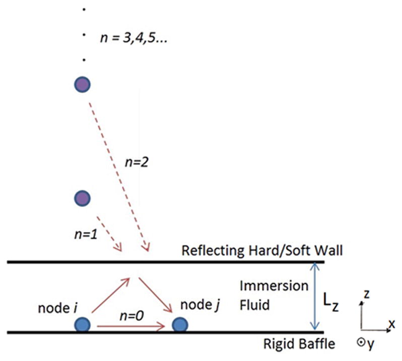
Geometry used for derivation of the modified Green’s function via method of images
As described in Appendix A, this approach can be extended to multiple hard/soft walls at different angles to simulate CMUT arrays in enclosures or finite space such as microfluidic channels, and also take advantage of different symmetry conditions in the array. In case of a hard wall boundary which may be tilted as compared with the plane containing the CMUT array, proper geometrical modifications can be made to (8). Pulse-echo directivity pattern can be obtained given that the distance between the transducer and the hard wall boundary is large enough. By investigating the time domain pressure fields propagating back and forth between the array and the hard wall, one can also evaluate the reflectivity of the CMUT array accurately for different electrical loading conditions.
IV. Receive Model
In the formulation described above, one needs to develop a BEM mesh that includes all the transmitters and receivers in the array, resulting in a large numerical problem. In case the transmitters and receivers are physically close and interacting during the transmit event such as in a phased array, this is justified. However, if there is significant distance between a reflector and the transducer for a monostatic pulse-echo operation, then one can treat the transmission, propagation, and receive phases separately, reducing the size of the BEM problem. Furthermore, when CMUTs are used in pitch-catch mode or receive-only mode such as in photoacoustic imaging applications, a separate BEM model can be used.
In receive mode operation, the critical step is the proper inclusion of the incident pressure field in the formulation. Given the mass M, stiffness K, matrices of the BEM formulation in (3), the linear acoustic response of the array can be calculated in the presence of an incident pressure field, pin. As in the case of any elastic structure, the total pressure field can be obtained as the sum of the incident and reflected fields from the perfectly rigid version of the structure, which is termed as the blocked pressure, pbl, and the radiated pressure field calculated due to the structural vibrations [35]. This leads to the following force balance equation for each node
| (10) |
Here the uj is the displacement of jth node and u is the nodal displacement vector. The third term on the left is the radiated field due to vibration of the whole array surface with nodal area, S. The pbl,j term is the blocked pressure acting on node j, and pES,j is the electrostatic pressure vector acting on the node.
It is difficult to obtain the blocked pressure for structures with irregular geometries because of diffraction effects, however for a vibrating surface on an infinite planar baffle it is simply pbl = 2pin everywhere on the surface, the usual pressure doubling condition [35]. Because the finite size BEM mesh is considered moving on an infinite rigid baffle, this assumption holds. In addition, for a small piston where ka ≪ 1 (this is the case for the nodes in the BEM mesh), the incident field on the piston can be assumed uniform, which further simplifies the derivation. Then, the time domain force balance equation governing the jth BEM node in the presence of an incident sound field becomes
| (11) |
This equation allows one to calculate the overall pressure in the field without a priori knowledge of the reflection from the array. The reflection from the array can be calculated by knowledge of the total field and the incident field. Validation of this approach is performed through a linear mechanical problem presented in Appendix B: The same transmit-receive problem is solved first as a single coupled BEM problem and then as an uncoupled transmit-propagation-receive problem where the array motion on the receiver array is obtained from the blocked pressure field generated by the transmitter. Both approaches give identical results when transmitter and receiver are far away.
The reduced order lumped modeling approach can be pursued similar to transmit modeling where the total forces and displacements of membrane patches are system variables. The total driving force acting on patch m is Fm = FES,m + 2Fin,m. Here FES,m is the total electrostatic force acting on the electrode patch and Fin,m is the total force acting on the patch due to the incident sound field, i.e.
| (12) |
where the summation is done over the mth patch.
In general, (11) is nonlinear due to the gap dependence of the electrostatic pressure; hence, the solutions for the electrostatic pressure and the incident field cannot be separated using the superposition principle. For incident fields with low amplitudes in comparison with the applied static electrostatic pressure by the dc bias, linear models around an operating point are applicable [29]. However, the linear solution is dependent on the dc bias because of the spring softening effect; therefore, the linear system must be solved for every different dc bias configuration. On the other hand, the nonlinear lumped model enables investigation of receiver nonlinearity, CMUT response to high incident pressure under difference bias levels in addition to linear receiver applications. Furthermore, because the lumped modeling approach reduces the number of variables to solve significantly, this approach would be useful even for small signal simulations at different bias levels.
The resulting SIMULINK model is shown in Fig. 4 where the total forces due to the incident field and electrostatic actuation are added for transient array simulation in receive mode. The receive circuitry is incorporated in the model with its output impedance assuming the interface circuit is linear within the operation range. Assuming a bias voltage VDC(t), the resulting circuit with the addition of the receive impedance is shown in Fig. 4, where the voltage acting on the CMUT capacitance, V(t), and the CMUT output current, i(t), are calculated as
Fig. 4.

(Left) Electrical circuit for receive operation employing the CMUT as a variable capacitor (Right) SIMULINK Model for Receive Mode
| (13) |
Another common configuration utilizing a biasing tee circuit is shown in Fig. 5. The biasing tee simply applies the dc bias to the CMUT and it lets the output current flow into the receive impedance [36]. In this case the voltage acting on the CMUT is
| (14) |
and the corresponding SIMULINK model is shown in Fig. 5.
Fig. 5.

(Left) Electrical circuit for receive operation with a bias tee circuit (Right) SIMULINK Model for Receive Mode with the bias tee circuit
In the simulations, the application of the dc bias as a sharp Heaviside function at the beginning of the simulation results in added dynamics resulting from the introduction of the dc bias as well as numerical issues regarding the sharp transition and excitation of very high frequencies. Therefore the bias Vdc(t) is defined as varying with time so smooth initializations of the dc bias is realizable and to cover dynamic dc biasing scenarios without the loss of generality [12], [37].
With the output signal available, and knowing the noise characteristics of the CMUT element and electronics through their electrical impedances, one can obtain the signal to noise ratio for given pressure input. Hence the model is useful in computing the minimum detectable pressure of the array elements considering the parameters of the integrated system.
V. Model Verification & Example CMUT Modeling Results
Different aspects of the presented models are verified by comparison to COMSOL simulations. The examples are chosen such that they also illustrate some recent concepts for nonlinearity reduction, receiver optimization and CMUTs in confined spaces. In these simulations a single circular CMUT membrane with multiple electrode elements is used in transmit, pulse-echo, and receiver modes. This shape and configuration are chosen to further demonstrate the flexibility of the model in terms of membrane shape (earlier examples used square membranes) and in terms of electrode structure. The model size is kept small to have a computationally feasible size for the FEA model as it gets computationally more expensive with increasing number of array elements. A 2-μm-thick SiNX circular CMUT element is modeled as the example device. The CMUT membrane radius is 20 μm. The device has 50 nm gap, no electrode isolation, 75% electrode coverage, and is immersed in water. The transducer has 8.5-MHz center frequency and the collapse voltage is 13 V. The membrane is separated into 3 patches based on the modal analysis of the membrane for increased accuracy and also to have the capability of simulating a dual-electrode CMUT as described below. The overall dimensions of the membrane are arbitrary and not targeted for a particular application. The meshed membrane is shown in Fig. 6.
Fig. 6.

The simulated circular CMUT membrane with 75% electrode coverage. The membrane is modeled via 3 patches with coupled dynamics.
A. Transmit Model
The modeled CMUT is first simulated in transmit mode for harmonic distortion analysis both with the presented method and COMSOL. We simulated a dualelectrode CMUT structure with separate electrodes connected to different driver circuitry to show the generality of the model. The simulated case is an example case for an harmonic reduction scenario using a series impedance feedback approach [21].
It has been reported previously that side electrode actuation of CMUTs results in reduced nonlinear behavior [38]. Because the dual-electrode CMUT structure presented in [38] makes use of leveraged bending [39], large membrane displacements can be attained while the side electrodes go under smaller displacements. Consequently, electrostatic nonlinearity is reduced as the electrode displacement is decreased for the same membrane displacement amplitude. When combined with the gap feedback method as shown in Fig. 7 (left), this property of the dual-electrode CMUT can further suppress the CMUT nonlinearity. This topology employs two feedback impedances connected in series to the side and center electrodes, driven by the same voltage source. As the CMUT is actuated and displaced, the voltages acting on both electrodes are adjusted by the resulting RC filter separately, as a function of each electrode’s individual displacement.
Fig. 7.

(Left) Dual electrode gap feedback topology (Right) Applied drive signal
This approach is implemented on the example CMUT shown in Fig. 6. The electrode patches A and B are utilized as separate center and side electrodes, respectively. The fundamental operation frequency is selected as 5 MHz, so both the fundamental and the second harmonic component at 10 MHz are within the operation band of the device as this would be a case for a typical harmonic imaging scenario. The device is actuated with an 11 V, 2.5 MHz sine wave enveloped by a 300-ns Gaussian signal and no dc bias [Fig. 7 (right)]. It should be noted that as the device is driven without dc bias, the fundamental component of the output pressure is at twice the frequency of excitation [21]. The resulting time domain mean membrane displacement and the output pressure at 20 μm away from the transducer are shown in Figs. 8(a) and 8(c) for the no feedback case. Figs. 8(b) and 8(d) shows the results for the dual electrode gap feedback implementation where the transducer is driven by amplitude doubled 22 V excitation signal and 3 MΩ and 1 MΩ feedback resistors are used as feedback components for center and side electrode, respectively. The resistance values were selected according to the gap feedback scheme presented in [21], and they apply a larger feedback gain to the center electrode, which behaves more nonlinearly compared with the side electrode. Both selected resistance values set the cutoff frequency of the resulting RC filters when the CMUT is at rest to ~1.6 MHz, which is smaller than the excitation frequency as required for gap feedback to work. The pressure spectra for the cases with and without feedback are given in Fig. 8(e). Using the dual electrode feedback topology, the 2nd harmonic magnitude is suppressed by ~12 dB, reducing the harmonics ~23 dB below the fundamental by doubling the input voltage. The results show excellent agreement with the COMSOL simulations, demonstrating the versatility and the accuracy of the model.
Fig. 8.

(a) Time domain displacement for conventional single electrode operation (b) Time domain displacement for dual electrode gap feedback operation (c) Transmitted pressure for conventional single electrode operation (d) Transmitted pressure for dual electrode gap feedback operation (e) Spectra of the transmitted pressure for conventional single electrode and dual electrode gap feedback operation.
B. Pulse-Echo Model
For the pulse-echo model verification, the example circular CMUT is placed 20 μm away from a parallel rigid wall, and the time domain the mean membrane displacement of the CMUT is calculated and compared with COMSOL simulations. It should be noted that the model is capable of simulating a plane reflector located at an arbitrary distance from the CMUT. However, 20 μm is selected to keep the FEA model size small because the fluid domain between the wall and the CMUT must be meshed fine enough to accurately model the wave propagation within the immersion medium.
The CMUT is actuated with a 25 V Gaussian pulse with 8 ns standard deviation and the source impedance, which acts as the load impedance in the receive mode, is selected as 50 kΩ in the simulations. To clarify the effect of the hard wall in the calculations, the same CMUT is also simulated when it is immersed in a semi-infinite medium and when a soft wall reflector is present 20 μm away from the CMUT. Fig. 9 presents the time and frequency domain mean membrane displacements for the same excitation signal, in semi-infinite medium, hard wall and soft wall cases. In these simulations there is no parasitic capacitance and the electrical load is same for transmit and receive states, which overlap in time. Hence, the pulse-echo model reduces to the model in Fig. 1 if the electrical load is same for transmit and receive and there are no parasitics. The main difference is that the MIMO block is derived with appropriate modified Green’s function (8) or (9) for finite immersion medium. In all cases, model results show agreement with COMSOL calculations within 1 dB for most of the spectrum up to 4 times the center frequency of the device, validating the accuracy of the presented approach. It is clear from simulations that a CMUT facing a hard wall is damped significantly, whereas a free surface results in a stronger resonance.
Fig. 9.
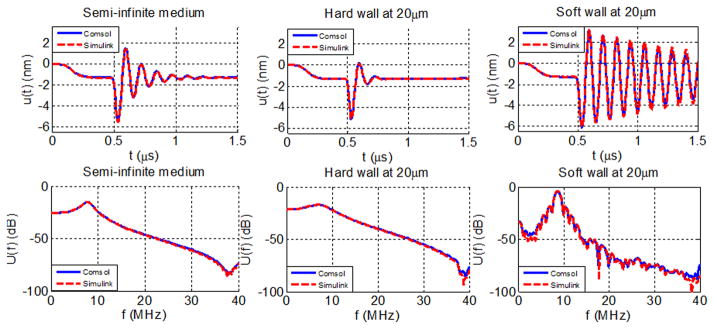
Mean membrane displacements and its spectra in semi-infinite fluid, in the presence of a hard wall 20 μm away from the transducer and in the presence of a soft wall 20 μm away when the CMUT is terminated with a 50 kΩ resistor.
C. Receive Only Model
To demonstrate the receive-only modeling capability with arbitrary electrical termination, the example circular CMUT is simulated for an incident plane wave with normal incidence when the CMUT is biased to 90% of its collapse voltage for short circuit and resistive termination cases. The resistance value, 50 kΩ, has no specific importance and is chosen to demonstrate that the presented model is capable of modeling an arbitrary chosen series resistive load with FEM accuracy. The electrical termination conditions affect the CMUT dynamics and the gain bandwidth product of a CMUT [40]. In the simulations, the incident plane wave is a Gaussian enveloped tone burst with 7 MHz center frequency and 1 kPa amplitude. The resulting mean membrane displacements averaged over the whole CMUT membrane and output currents are presented in Fig. 10, respectively, for short circuit and 50 kΩ terminations.
Fig. 10.

(a) Mean membrane displacement in receive mode for short circuit termination (b) Mean membrane displacement in receive mode when the CMUT is terminated with a 50 kΩ resistor (c) Output current for short circuit termination (d) Output current for 50 kΩ resistive termination (e) Output current spectra in receive mode for short circuit termination and when the CMUT is terminated with a 50 kΩ resistor.
It should be noted that in this case the CMUT has only one electrode, which is modeled by two patches for improved electromechanical simulation accuracy. Therefore the output current is the sum of the current outputs of both patches. The discrepancy of mean membrane displacements and the calculated output currents between the COMSOL and the SIMULINK model results is less than 1%. This small set of results show that bandwidth of the receiving CMUT is improved while the receive gain is reduced with resistive loading, indicating the possibility of optimizing the device performance with certain tradeoffs. In this case for resistive termination, higher resistance values result in broader bandwidth with decreased sensitivity.
VI. Application of the Model: Simulation of A Partial Dual-Ring Array in Pitch-Catch Operation
As an application of the model for a practical case and to provide an experimental comparison, a 25 MHz dual ring CMUT-on-CMOS array is modeled. Details of the array shown in Fig. 11 are described elsewhere [28]. Also shown in the figure is the part of the array that is modeled, with 11 transmit (outer ring) and 11 receive (inner ring) elements where each array element is composed of four 25 μm × 25 μm membranes with 80% electrode coverage.
Fig. 11.

Modeled dual-ring array for Forward Looking IVUS and applied drive signals
The experimental device has on-chip pulsers and there is no access to the electrical transmit pulse. Therefore, an approximate pulse given in Fig. 11 where the standard deviation of the Gaussian pulse is 7 ns is applied to the transmitting element in the simulations. The dc bias applied to the transmit ring is selected as 15 V and the drive pulse amplitude is selected as 25 V. These values are based on the fabricated CMUT-on-CMOS array with on-chip 25 V pulsers and 40 V dielectric breakdown voltage [28]. The collapse voltage of the CMUT is 39 V. The magnitude of the input impedance of the transimpedance amplifiers connected to the receive elements is estimated to be around 10 kΩ and the TIA gain to be 300 kV/A from circuit simulations. It should be noted that the dc bias is applied to the CMUT array using a smooth function to avoid additional membrane dynamics due application of the dc bias.
The array is modeled in water and the pulse-echo response is calculated for the water-air interface 1 cm away from the array as in the experiments. The highlighted elements in Fig. 11 are used as the transmitter and the receiver in the experiment and simulations. Fig. 12 compares the received signals from experiments and from the model. Considering the CMUT and CMOS fabrication uncertainties, unaccounted reflections from the wire-bonds and the boundary conditions of the doughnut substrate in the experiment, and the estimated excitation pulse, the results match fairly well validating the calculations.
Fig. 12.

Experimental and simulated received signals from the water-air interface 1 cm away from the CMUT array
The model is useful not only generating an output signal, but it also enables one to explore other important practical information on current levels during different phases of the transmit/receive cycle, acoustic crosstalk as well as optimization. As an example, the particular model for the dual-ring array is used for a simple optimization study where the output current of the receive element is calculated for three cases with different receive dc bias and receive termination conditions (Fig. 13). In the first case, the receive ring is biased to 95% of the collapse voltage (37 V) and the magnitude of the receive amplifier input impedance is 10 kΩ (solid, blue). In the second case the receive ring is biased to 77% of the collapse voltage (30 V) (dashed, red). As the third case (dashed, black), the receive ring is biased to 95% of the collapse voltage (37 V) and the electrical boundary termination is set as short circuit. The time domain output current signals are given in Fig. 13 for three separate cases. The output current for each case is composed of three parts as labeled in the plot. First, current flows into CMUT from the source as charge builds up on the CMUT capacitance, whereas the dc bias to the receive ring is being applied using a smooth function similar to the transmit ring, where the applied signal is shown in Fig. 11 as a function of time. Second, the receive element responds to the radiated pressure from the transmit element and outputs a signal due to the acoustic crosstalk [Fig. 13(b)]. Finally the receive element responds to the echo signal reflected from the water-air interface [Fig. 13(c)]. Fig. 13(e) presents the spectra of the received echo signals for the simulated cases. Simulation results suggest that the 2-way gain and bandwidth are both improved as the receive ring is biased close to collapse and for short circuit receive termination condition compared with the first case.
Fig. 13.
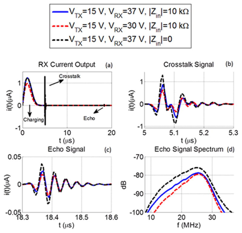
Time and frequency domain output currents of the receiving element when the modeled dual-ring array is simulated in pitch-catch operation utilizing the water-air interface 1 cm away from the array for different receive ring bias and electrical termination conditions
In these computations, the mesh size for the BEM formulation is 1.67 μm. The calculation of the model parameters up to 100 MHz with a frequency resolution of 50 kHz (20 μs time response calculation) takes approximately 5 h via parallel computing with 20 computing nodes in a high performance computing cluster each utilizing 5 processors and 48 GB physical memory in the Matlab environment. Note that the computation time is directly proportional to the number of processors and the frequency resolution required for the desired output time signal duration. After calculation of the model parameters, the time-domain SIMULINK model calculates the received signals from the water-air interface for the given drive signals for each electrode patch in the array and the electrical terminations. The simulation takes approximately 15 min to calculate the array response for 20 μs simulation time with 5 ns time step for any input signal, gap thickness, transmit/receive electronics combination using a desktop computer with an Intel i5 processor running at 3 GHz and 16 GB of RAM. Note that any change in these parameters would require a separate transient 3-D FEA of this partial array, which is practically infeasible. Therefore, this example demonstrates the potential of the modeling approach for rapid iterative optimization of CMUT arrays where FEA accuracy is achieved in a computationally efficient manner.
VII. Conclusion
A large signal transmit model for CMUT arrays is extended to simulate ultrasound system response with source and receive impedances. By interfacing the model with an electronics simulator such as SPICE, more complex driver and receiver electronics can be included for a complete system model. The extended capabilities of the model, the electrical termination for each array element in transmit mode, pulse-echo operation in the presence of a flat hard wall reflector and receive operation for a given incident field together with receive electronics, are all validated via comparisons with 3-D FEA implemented in COMSOL. The validation examples highlight the versatility of the model for different ultrasound applications such as harmonic imaging and comparison with piezoelectric transducers through pulse-echo measurements as well as CMUTs operated in confined spaces. With its computational efficiency and accuracy, the model paves the way for optimization of CMUT arrays for various applications. As an example, the system response of a particular single chip CMUT-on-CMOS IVUS imaging system is calculated on a parallel computing cluster to investigate dc bias optimization. Considering the phenomena such as CMUT nonlinearity and array crosstalk are active research topics, the modeling tool should be valuable for CMUT researchers in its present form. In addition, the presented model can form the core of a virtual design tool for CMUT-based imaging systems when coupled with commercial software tools such as COMSOL and SPICE as well as image simulators such as FIELD II.
TABLE B-I.
Used Dimensions and Material Properties
| Membrane dimensions | 30 μm × 30 μm |
| Number of nodes per membrane | 15 × 15 |
| Membrane thickness | 2 μm |
| Membrane density, ρ | 2040 kg/m3 |
| Poisson’s ratio of membrane | 0.22 |
| Young’s modulus of membrane | 110 GPa |
| Density of immersion medium | 1000 kg/m3 |
| Speed of sound in immersion medium | 1500 m/s |
APPENDIX A. BEM Formulation for CMUT Arrays with Symmetry and CMUT Arrays in Enclosures
A. Model with Half and Quarter Symmetry
The method of images technique used in Section II for pulse echo operation can be used to reduce the BEM problem size by half for half symmetry and to its quarter for quarter symmetry if the modeled array exhibits symmetry in terms of geometry and electrical excitation. Symmetry in the acoustic domain is represented by a rigid wall at the symmetry axis and method of images is utilized to modify the Green’s function to account for the boundary conditions introduced by the rigid walls [33], [41]. For half symmetry around x-axis with the symmetry axis located at x = 0 the Green’s function relating the displacement of node i and the fluid loading on node j is composed of the direct coupling term and the reflection from the rigid wall, modeled by the image source located at (−xi,yi) such that
| A1 |
Similarly, quarter symmetry is modeled by two perpendicular rigid walls located at x=0 and t=0, resulting in the modified Green’s function
| A2 |
where the images of the source node are located at (−xi, yi), (xi, −yi) and (−xi, −yi).
B. CMUT Array model in an enclosure
The vibroacoustic behavior of a CMUT array in a rectangular enclosure with hard or soft walls can also be calculated via method of images. An example scenario for such a case is a resonant fluid sensor where a CMUT array is placed in an enclosure to measure the fluid properties like mass and density, where the presence of the hard wall enclosure results in a high Q resonance of the surface waves on the CMUT array [15]. In this case the Green’s function is modified to take the multiple reflections in all three dimensions in the presence of six walls, including the rigid baffle the CMUT array is placed on. The modified Green’s function between a point source and a point receiver located in arbitrary locations (xi, yi, zi) and (xj, yj, zj) in the enclosure with dimensions (Lx, Ly, Lz) is
| A 3 |
as formulated in [41] for calculation of the reverberation properties of a small room. It should be noted that in this case CMUT membranes can be modeled on any wall of the enclosure. As discussed in the pulse-echo section, with some loss, as the number of reflections (l, m, n) go to ∓∞ the amplitude of the contributions from images decrease, hence the summation converges.
APPENDIX B. Receive-only Acoustic CMUT Array Model Verification
The linear receive-only model is validated by modeling two CMUT elements on the same rigid baffle in a semi-infinite fluid, where one CMUT element is used as a transmitter and the second element as the receiver. First, both transmitter and receiver elements are modeled together with the BEM formulation given in (3), while only the transmit membranes are excited. Because the BEM formulation handles the wave propagation, the dynamics of the receiver membranes are calculated in the coupled problem. In the second case, first, only the transmitter membranes are modeled for the same excitation signal, and then the blocked pressure field pbl is calculated using Rayleigh integral approximation on the points on the rigid surface where the nodes of the receiver array is located. Finally, using the radiated blocked field pbl as the excitation term, the response of the receiver membranes is calculated via (10), and the electrostatic pressure is omitted. The results are compared to test the validity of the approach.
The simulated geometry is shown in Appendix Figure B1 where membranes 1,2,3,4 are used to transmit and membranes 5,6,7,8 located 3 mm away from the transmitter array are used to receive the transmitted ultrasound wave. Simulated CMUT parameters are given in Table I. In the first case, all eight membranes are simulated when the transmitter membranes 1,2,3,4 are excited with uniform pressure and no excitation pressure is applied to the membranes 5,6,7,8. The BEM problem is solved up to 50 MHz with 100 kHz resolution and the applied pressure signal is 200 ns long Hann windowed 15 MHz tone with 1 MPa amplitude. The mean displacements of the receiver membranes 6 and 8 are given in Appendix Figure B2 (solid line). The arrival of the acoustic wave around 2 μs to membrane 6 and the delay between the membranes are as expected, and no effect of the receiver on the transmitter is expected until 4 μs. In this case the size of the BEM matrix is 1800 × 1800.
Fig. B1.

Simulated array geometry for validation of the linear receive model
Fig. B2.

Mean displacements of the receiver membranes 6 and 8
In the second case, first the response of the transmitter elements is calculated for the same excitation pressure. In this case the size of the BEM matrix is 900 × 900 because only four membranes are simulated. The pressure field on the receiver node locations is calculated as
| B 1 |
where ui is the complex displacement of the transmitter node i, and ri,j is the distance between the transmitter node i and the receiver node j. This is the blocked field because the model includes rigid boundary conditions except for the transmit membrane locations. Using the calculated blocked field, the response of the receiver array is calculated separately with the forcing vector pbl, again with the BEM matrix size 900 × 900. Calculated mean displacements of membranes 6 and 8 are given in Appendix Figure B2 (dashed line). The results are identical with the case where the whole problem is solved in a single step within the relevant time scale, validating the receive modeling formulation. In this example, the large separation of the transmit-receive problem enables one to separate transmit, wave propagation, and reception problems, and reduces the total computation time to one-third. However, the approach will not work when the transmit and receive elements are close to each other because the reflections from the receive element affect the transmitter response.
References
- 1.Fisher TG, Hall TJ, Panda S, Richards MS, Barbone PE, Jiang J, Resnick J, Barnes S. Volumetric elasticity imaging with a 2-D CMUT array. Ultrasound Med Biol. 2010;36(6):978–990. doi: 10.1016/j.ultrasmedbio.2010.03.019. [DOI] [PMC free article] [PubMed] [Google Scholar]
- 2.Stephens DN, O’Donnell M, Thomenius K, Dentinger A, Wildes D, Chen P, Shung KK, Cannata J, Khuri-Yakub P, Oralkan O, Mahajan A, Shivkumar K, Sahn DJ. Experimental studies with a 9F forward-looking intracardiac imaging and ablation catheter. J Ultrasound Med. 2009;28(2):207. doi: 10.7863/jum.2009.28.2.207. [DOI] [PMC free article] [PubMed] [Google Scholar]
- 3.Savoia AS, Caliano G, Pappalardo M. A CMUT probe for medical ultrasonography: From microfabrication to system integration. IEEE Trans Ultrason Ferroelectr Freq Control. 2012;59(6):1127–1138. doi: 10.1109/tuffc.2012.2303. [DOI] [PubMed] [Google Scholar]
- 4.Certon D, Senegond N, Gross D, Legros M, Boulme A, Roman B, Teston F, Ferin G. Dual mode cMUTs fabricated with LPCVD sacrificial release process. 2011 IEEE Int Ultrasonics Symp. :604–607. [Google Scholar]
- 5.Daft C, Calmes S, da Graca D, Patel K, Wagner P, Ladabaum I. Microfabricated ultrasonic transducers monolithically integrated with high voltage electronics. 2004 IEEE Ultrasonics Symp. 1:493–496. [Google Scholar]
- 6.Nikoozadeh A, Khuri-Yakub PT. CMUT with substrateembedded springs for non-flexural plate movement. 2010 IEEE Ultrasonics Symp. 2010:1510–1513. doi: 10.1109/ULTSYM.2010.5936014. [DOI] [PMC free article] [PubMed] [Google Scholar]
- 7.Hitachi-Medical-Corp. Hitachi Mappie CMUT Ultrasound Probe. 2009 Available: http://www.hitachi-medical.co.jp/tech/medix/pdf/vol51/P31-34.pdf.
- 8.Nikoozadeh A, Oralkan O, Gencel M, Choe JW, Stephens DN, de la Rama A, Chen P, Feng L, Dentinger A, Wildes D, Thomenius K, Shivkumar K, Mahajan A, Seo CH, O’Donnell M, Truong U, Sahn DJ, Khuri-Yakub PT. Forward-looking intracardiac imaging catheters using fully integrated CMUT arrays. 2010 IEEE Ultrasonics Symp. 2010:770–773. [Google Scholar]
- 9.Jeong B-G, Kim D-K, Hong S-W, Chung S-W, Shin H-J. Performance and reliability of new CMUT design with improved efficiency. Sens Actuators A Phys. 2013;199:325–333. [Google Scholar]
- 10.McLean J, Guldiken RO, Degertekin FL. CMUTs with dual electrode structure for improved transmit and receive performance. 2004 IEEE Ultrasonics Symp. 2004:501–504. doi: 10.1109/tuffc.2006.1593388. [DOI] [PubMed] [Google Scholar]
- 11.You W, Cretu E, Rohling R. Super-resolution imaging using multi-electrode CMUTs: Theoretical design and simulation using point targets. IEEE Trans Ultrason Ferroelectr Freq Control. 2013;60(11):2295–2309. doi: 10.1109/TUFFC.2013.6644734. [DOI] [PubMed] [Google Scholar]
- 12.Guldiken RO, Balantekin M, Zahorian J, Degertekin F. Characterization of dual-electrode CMUTs: Demonstration of improved receive performance and pulse echo operation with dynamic membrane shaping. IEEE Trans Ultrason Ferroelectr Freq Control. 2008;55(10):2336–2344. doi: 10.1109/TUFFC.933. [DOI] [PMC free article] [PubMed] [Google Scholar]
- 13.Vaithilingam S, Ma T-J, Furukawa Y, Wygant IO, Xuefeng Z, De La Zerda A, Oralkan O, Kamaya A, Gambhir SS, Jeffrey RB, Jr, Khuri-Yakub BT. Three-dimensional photoacoustic imaging using a two-dimensional CMUT array. IEEE Trans Ultrason Ferroelectr Freq Control. 2009;56(11):2411–2419. doi: 10.1109/TUFFc.2009.1329. [DOI] [PubMed] [Google Scholar]
- 14.Gurun G, Hochman M, Hasler P, Degertekin F. Thermalmechanical-noise-based CMUT characterization and sensing. IEEE Trans Ultrason Ferroelectr Freq Control. 2012;59(6):1267–1275. doi: 10.1109/TUFFC.2012.2317. [DOI] [PMC free article] [PubMed] [Google Scholar]
- 15.Thranhardt M, Eccardt P-C, Mooshofer H, Hauptmann P, Degertekin L. A resonant CMUT sensor for fluid applications. 2009 IEEE Sensors. :878–883. [Google Scholar]
- 16.McLean J, Degertekin FL. Interdigital capacitive micromachined ultrasonic transducers for sensing and pumping in microfluidic applications. 12th Int. Conf. on Transducers, Solid-State Sensors, Actuators and Microsystems; 2003. pp. 915–918. [Google Scholar]
- 17.Viržonis D, Kodzius R, Vanagas G. Integration of capacitive micromachined ultrasound transducers to microfluidic devices. In: Panzarella S, Maroni W, editors. Microfluidics: Control, Manipulation and Behavioral Applications. New York, NY, USA: Nova Publishers; 2013. pp. 127–150. [Google Scholar]
- 18.Khuri-Yakub BT, Degertekin FL. Google Patents. 2005. Fluidic device with integrated capacitive micromachined ultrasonic transducers. [Google Scholar]
- 19.Ozeri S, Shmilovitz D. Ultrasonic transcutaneous energy transfer for powering implanted devices. Ultrasonics. 2010;50(6):556–566. doi: 10.1016/j.ultras.2009.11.004. [DOI] [PubMed] [Google Scholar]
- 20.Legros M, Novell A, Bouakaz A, Ferin G, Dufait R, Certon D. Tissue harmonic imaging with CMUTs. 2011 IEEE Int Ultrasonics Symp. :2249–2252. [Google Scholar]
- 21.Satir S, Degertekin FL. Harmonic reduction in capacitive micromachined ultrasonic transducers by gap feedback linearization. IEEE Trans Ultrason Ferroelectr Freq Control. 2012;59(1):50–59. doi: 10.1109/TUFFC.2012.2155. [DOI] [PMC free article] [PubMed] [Google Scholar]
- 22.Matrone G, Savoia A, Terenzi M, Caliano G, Quaglia F, Magenes G. A volumetric CMUT-based ultrasound imaging system simulator with integrated reception and μ-beamforming electronics models. IEEE Trans Ultrason Ferroelectr Freq Control. 2014;61(5):792–804. doi: 10.1109/TUFFC.2014.6805693. [DOI] [PubMed] [Google Scholar]
- 23.Senegond N, Boulme A, Plag C, Teston F, Certon D. Fast time-domain modeling of fluid-coupled cMUT cells: From the single cell to the 1-D linear array element. IEEE Trans Ultrason Ferroelectr Freq Control. 2013;60(7):1505–1518. doi: 10.1109/TUFFC.2013.2723. [DOI] [PubMed] [Google Scholar]
- 24.Gross D, Boulme A, Perroteau M, Certon D, Senegond N. Control and monitoring of dynamic collapse event in cMUTs arrays for therapeutic applications. 2012 IEEE Int Ultrasonics Symp. :1830–1833. [Google Scholar]
- 25.Atalar A. Rayleigh bloch waves in CMUT arrays. IEEE Trans Ultrason Ferroelectr Freq Control. 2014;61(12):2139–2148. doi: 10.1109/TUFFC.2014.006610. [DOI] [PubMed] [Google Scholar]
- 26.Satir S, Zahorian J, Degertekin FL. A large-signal model for CMUT arrays with arbitrary membrane geometry operating in non-collapsed mode. IEEE Trans Ultrason Ferroelectr Freq Control. 2013;60(11):2426–2439. doi: 10.1109/TUFFC.2013.6644745. [DOI] [PMC free article] [PubMed] [Google Scholar]
- 27.Satir S, Degertekin FL. A computationally efficient nonlinear system model for CMUT arrays. 2014 IEEE Int Ultrasonics Symp. :313–316. [Google Scholar]
- 28.Gurun G, Tekes C, Zahorian J, Xu T, Satir S, Karaman M, Hasler J, Degertekin FL. Single-chip CMUT-on-CMOS frontend system for real-time volumetric IVUS and ICE imaging. IEEE Trans Ultrason Ferroelectr Freq Control. 2014;61(2):239–250. doi: 10.1109/TUFFC.2014.6722610. [DOI] [PMC free article] [PubMed] [Google Scholar]
- 29.Meynier C, Teston F, Certon D. A multiscale model for array of capacitive micromachined ultrasonic transducers. J Acoustical Soc Am. 2010;128(5):2549–2561. doi: 10.1121/1.3493433. [DOI] [PubMed] [Google Scholar]
- 30.Timoshenko S. Theory of Plates and Shells 2E. New York, NY, USA: McGraw-Hill; 1959. [Google Scholar]
- 31.Carstensen EL. Self-reciprocity calibration of electroacoustic transducers. J Acoust Soc Am. 1947;19(6):961–965. [Google Scholar]
- 32.Courant R, Friedrichs K, Lewy H. On the partial difference equations of mathematical physics. IBM J Res Develop. 1967;11:215–234. [Google Scholar]
- 33.Kinsler LE, Frey AR, Coppens AB, Sanders JV. Fundamentals of Acoustics. New York, NY, USA: Wiley; 1999. [Google Scholar]
- 34.Lee KL, Lau C-P, Tse H-F, Echt DS, Heaven D, Smith W. First human demonstration of cardiac stimulation with transcutaneous ultrasound energy delivery implications for wireless pacing with implantable devices. J Am Coll Cardiol. 2007;50:877–883. doi: 10.1016/j.jacc.2007.04.081. [DOI] [PubMed] [Google Scholar]
- 35.Fahy FJ, Gardonio P. Sound and Structural Vibration: Radiation, Transmission and Response. New York, NY, USA: Elsevier Science; 2007. [Google Scholar]
- 36.Ergun AS, Yaralioglu GG, Khuri-Yakub BT. Capacitive micromachined ultrasonic transducers: Theory and technology. J Aerosp Eng. 2003;16(2):76–84. [Google Scholar]
- 37.Barnes S, Bolorforosh M, Phelps R. Bias control of electrostatic transducers. 6795374 B2. US Patent US. 2004 Sep 21;
- 38.Guldiken RO, McLean J, Degertekin FL. CMUTS with dual electrode structure for improved transmit and receive performance. IEEE Trans Ultrason Ferroelectr Freq Control. 2006;53(2):483–491. doi: 10.1109/tuffc.2006.1593388. [DOI] [PubMed] [Google Scholar]
- 39.Hung ES, Senturia SD. Extending the travel range of analog-tuned electrostatic actuators. J Microelectromechanical Systems. 1999;8(4):497–505. [Google Scholar]
- 40.Olcum S, Senlik MN, Atalar A. Optimization of the gainbandwidth product of capacitive micromachined ultrasonic transducers. IEEE Trans Ultrason Ferroelectr Freq Control. 2005;52(12):2211–2219. doi: 10.1109/tuffc.2005.1563264. [DOI] [PubMed] [Google Scholar]
- 41.Allen JB, Berkley DA. Image method for efficiently simulating small-room acoustics. J Acoust Soc Am. 1979;65(4):943–950. [Google Scholar]