Abstract
The objective of the present study was the development and clinical testing of a three-dimensional (3D) reconstruction method of teeth and a bone tissue of the jaw on the basis of CT images of the maxillofacial region. 3D reconstruction was performed using the specially designed original software based on watershed transformation. Computed tomograms in digital imaging and communications in medicine format obtained on multispiral CT and CBCT scanners were used for creation of 3D models of teeth and the jaws. The processing algorithm is realized in the stepwise threshold image segmentation with the placement of markers in the mode of a multiplanar projection in areas relating to the teeth and a bone tissue. The developed software initially creates coarse 3D models of the entire dentition and the jaw. Then, certain procedures specify the model of the jaw and cut the dentition into separate teeth. The proper selection of the segmentation threshold is very important for CBCT images having a low contrast and high noise level. The developed semi-automatic algorithm of multispiral and cone beam computed tomogram processing allows 3D models of teeth to be created separating them from a bone tissue of the jaws. The software is easy to install in a dentist's workplace, has an intuitive interface and takes little time in processing. The obtained 3D models can be used for solving a wide range of scientific and clinical tasks.
Keywords: cone beam computed tomography, spiral computed tomography, computer-assisted image processing, 3D dental model, digital dentistry
Introduction
The use of X-ray radiation is an integral part of dental practice at different clinical stages such as the determination of disease presence and severity, planning of treatment, monitoring of disease progression, assessment of treatment efficacy etc.
The arrival of CT, which allows dentists to receive extensive information, was an important step towards improving the diagnostics in dentistry. However, before the advent of CBCT, the use of tomography in dentistry had been limited because of large radiation exposures, high prices and the large size of equipment. In dentistry, CBCT is mainly used as it is devoid of the above-mentioned drawbacks.
The process of CBCT image production consists of the following four key components: image acquisition configuration (current and voltage parameters, the parameters of resolution and field of view), registration (determined by the type of scanner detector), reconstruction and image display on the monitor.1 The stages of registration and reconstruction are not visible to a dentist and are determined by the technical parameters of the scanner. While working with CT images, the doctor spends most of the time analysing the final image on a computer monitor. The most important criteria for dentists in comparing and choosing different CBCT scanners are the possibilities for information presentation and the availability of different functions for the final image processing.
The standard viewing function package usually includes zoom, brightness, switching between windows, and interactive capabilities of linear and angular measurements without distortion. The work with flat images (two-dimensional images) on CT scanners is often realized in the form of multiplanar reconstruction, which represents windows displaying sections in multiplanar orthogonal planes and displaying sections in planes orthogonal to a pseudopanoramic reconstruction.
As each orthogonal series of sections contains a large amount of information about anatomical objects and therefore complicates the perception of a spatial interposition of organs and tissues by a dentist, various three-dimensional (3D) volume-rendering methods of computed tomograms have been developed to display the adjacent voxels. There are two groups of volume-rendering methods: direct and indirect. The first group is simpler for clinical use and requires less computer resources. Indirect 3D rendering is a complex process, which groups some voxels together and separates them from the rest of the data based on the differences in their intensity and density. This process is called segmentation. This procedure is technically difficult and requires considerable computer resources and a special software. During segmentation, the surface volume models of objects are obtained.
3D reconstruction can be carried out for crowns of teeth as well as for the entire teeth including roots. The creation of dental arches is quite promising in orthodontics and can replace or supplement scanning of models and impressions in the future.2,3 A volume reconstruction of each tooth individually, including roots, with the creation of a 3D model of the entire dentition is much more challenging. Some authors propose to use, for this purpose, the data obtained by different methods of examination.4 This approach allows more accurate 3D models to be obtained, but it requires a significant investment of time and resources.
Most manufacturers of CT scanners declare 3D capabilities of image reconstruction of the dental system. However, in reality, the image obtained when you work with the standard software does not allow separating the contours of teeth and a bone tissue of the jaws, since it is most often retrieved using a direct volume reconstruction method. For that reason, the doctor still needs to use the planar images in multiplanar projection mode for a detailed assessment of organs and tissues. Therefore, the majority of doctors who are accustomed to using planar images (intraoral or panoramic) in their practice do not see the benefits of current 3D reconstruction software functionalities.
The complexity of 3D reconstruction of the dental system and in the segmentation of objects is caused by several factors. The best modern CBCT scanners have a resolution of about 0.1 mm, whereas the multispiral CT scanners have a resolution >0.2 mm. However, the width of the periodontal ligament in the middle third of the root can be <0.1 mm, so the boundary between the alveolar bone proper and the cement of the tooth root is poorly visible on the radiograph.5,6 Simple technical increase in the resolution of CT would lead to a significant increase in the radiation dose to the patient, which will limit the use of the method in dentistry. The higher the resolution, the more the image noise, which also has a negative impact on the possibilities of segmentation. In addition, the similarity of the optical structure of the tooth cement and the bone tissue together with the absence of the periodontal ligament results in conjugation of the tooth and jaw contours. Approximal contacts and, when scanning with closed teeth, occlusal contacts with antagonists significantly complicate segmentation of individual teeth within the dentition. The separation of these organs into individual elements using standard image-processing algorithms delivered with CT scanners is not always possible. Spiral CT scanners have lower spatial resolution than do CBCT scanners, but the segmentation of the teeth and jaws in images of spiral CT is simpler because of higher contrast resolution, although the obtained 3D objects will have more distortion in size.7
In recent years, segmentation techniques using different processing algorithms are being actively developed.8,9 In addition to segmentation methods, the automatic teeth classification approach is quite promising.10 Unfortunately, most of these methods are still purely theoretical and cannot be widely used in dental practice.
All dental scanners have a function to export image data in the form of a set of files (tomograms) in digital imaging and communications in medicine 3 format. This format represents two-dimensional layers of a 3D image. It opens for the dentists, a possibility to use third party image-processing tools. However, existing software products are mostly designed for medical images obtained by spiral CT, as well as for the study of internal organs, where there is a high contrast of tissues. Therefore, it is necessary to develop a method and dedicated software product capable of processing computed tomograms of the maxillofacial region. A full 3D model of the dental system can be used for solving a wide range of diagnostic problems in dentistry.
Methods and materials
To fulfil research objectives, we have developed an algorithm and software that allows dentists to efficiently process computed tomograms exported from different CT scanners as digital imaging and communications in medicine or RAW files. User interface module was implemented using open source library Qt by Nokia (Espoo, Finland). It is free and supported on many platforms, including Windows® (Microsoft Corporation, Redmond, WA), Linux and Mac OS (Apple Inc., Cupertino, CA), which allows the creation of easily portable software. This library also supports creation of plug-ins, making it easy to expand and scale software. C++ was used as the main programming language. Mapping procedures were optimized by using OpenGL acceleration tools (Khronos Group, Beaverton, OR). Contrast and brightness correction as well as visualization of radiographic models were built using open GL shading language (GLSL).
Results
The processing of dental system images obtained during CT, and the creation of digital 3D models of the teeth and jaws is quite challenging. Unlike most of the internal organs, the developed algorithm of teeth and jaw segmentation is performed in five steps:
Step 1. Scanning patients with CT (multispiral CT or CBCT)
As a result of CT scanning, a set of digital imaging and communications in medicine files (tomograms) is stored and delivered to a workstation with the installed software. A dentist just selects the set of tomograms belonging to a patient and loads it into the application. The series of images of the upper and lower jaws in various spiral and CBCT scanners may be arranged in the form of separate sections or in the form of one file.
Step 2. Source data pre-processing
After a series of tomograms have been read, a 3D array (volume) is built by stacking up the loaded tomograms one by one. This volume is referred to as the source image or projection data. The brightness of each voxel of the source image represents the density of the corresponding point of the scanned tissue. To reduce image noisiness and to highlight bone structures, dentists can apply some kind of filtration at this step.
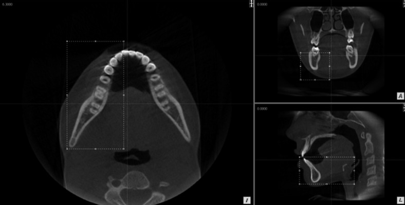
The work with 3D objects requires considerable computer resources, so it is necessary to select the area of interest for segmentation from the total set of data; it can be the entire jaw or its specific area (Figure 1). Most clinical cases in dental practice require a 3D model of a certain segment, which speeds up processing time as compared with full dentition. The separation of the teeth of the upper and lower jaws before segmentation significantly simplifies the process of 3D rendering. Therefore, the image with an open mouth is preferable. Otherwise, if the teeth are occluded, when selecting one of the jaws as the area of interest, the form of the occlusal surfaces will be partially distorted during reconstruction.
Figure 1.
Selection of the area of interest (left part of the mandible, including teeth from 32 to 38) on the original image for three-dimensional reconstruction. A, anterior (front view); I, inferior (bottom view); L, left (left view).
Step 3. Coarse segmentation
At this step, the dentist has to separate the jawbones, teeth and soft tissue from each other with the creation of two volume objects: the model of the entire dentition, which includes all teeth with roots and crowns from the selected area of interest; and the initial rough model of the jaw.
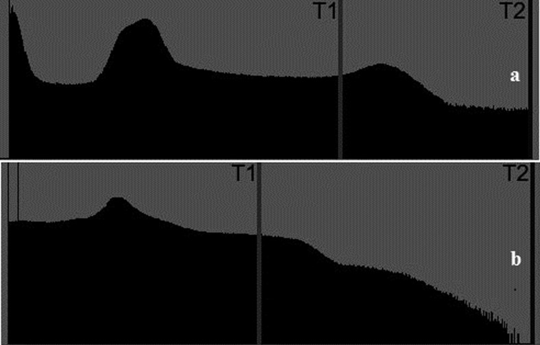
As brightness of each tomogram point depends on radio-opacity of the organ or tissue, it is possible to separate the segments of the image with the same radio-opacity by setting proper brightness threshold values. For this, the set of voxels of a manually selected area of interest is partitioned into the two classes they belong to: the objects and the background, using threshold-based segmentation technique. This technique uses two threshold levels between which voxels belong to object and others belong to background (Figure 2). Threshold selection process is carried out using voxel brightness histograms. The lower threshold value for segmentation is chosen by dentists so that voxels with intensity above an established threshold belong to the most optically dense part of the image points of the dental system: teeth and a compact jawbone tissue. High threshold is limited by the maximum value of volume voxels. As a result, the object contains the densest voxels (teeth and the most dense bone), whereas the background has soft tissue along with the rest of the bone and is excluded from further processes.
Figure 2.
Lower threshold selection on histogram for coarse segmentation (T1, lower threshold; T2, high threshold). (a) Histogram of multispiral CT image with pronounced peak of dense tissue (between T1 and T2); (b) histogram of CBCT image with smooth shift of optical density.
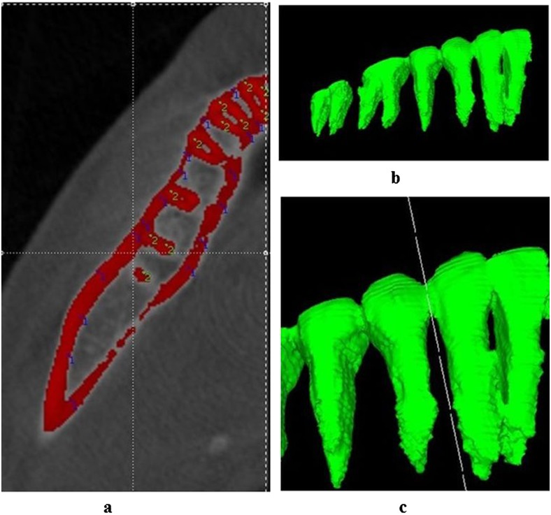
The coarse model of the jaw and teeth resulting from the previous stage needs to be further adjusted separating the teeth and jaws from each other. The teeth are separated from the jaws by a semi-automated technique using watershed transform.11 Unfortunately, it is impossible to fully automate the segmentation process; therefore, the markers corresponding to each object (the jaw and the teeth) should be placed on the original image. Dentists mark locally the brightest voxels of the jaws with Marker 1 and locally the brightest voxels of the teeth with Marker 2 (Figure 3a). To facilitate the recognition of individual objects, it is recommended to place markers on different slices of computed tomogram images in the multiplanar projection mode. The more markers placed, the higher the quality of 3D models obtained. Then, watershed transformation algorithm separates the jaws from the teeth using the markers. As a result, the algorithm creates two volume objects, corresponding to the positions of the markers—“Dentition” and “Coarse jaw” objects.
Figure 3.
(a) Placement of markers on the original image after threshold segmentation (blue 1, a jaw; green 2, teeth); (b) volume object “Dentition” after coarse segmentation; (c) the separation of the “Dentition” volume object into individual teeth with “virtual scissors”.
The image segmentation on high brightness threshold allows creating 3D models of teeth, dividing the root cement and alveolar bone proper (Figure 3b). If the obtained 3D teeth models are not of sufficient quality in the subjective evaluation, the program allows dentists to replace markers or change the threshold of segmentation and repeat the segmentation process again.
All artefacts significantly impede image segmentation, especially when there are metallic inclusions. Therefore, to simplify segmentation, the scanning technique must be strictly observed and several iterations of threshold segmentation selection on the histogram should be performed.
Step 4: Creation of “Jaw” volume object
The aim of the previous stage of segmentation is to create an accurate 3D model of the teeth. Since the density of the bone tissue in some regions may be quite low, certain parts of the jaw (especially the maxilla) with low mineralization are not included in creating 3D “Coarse jaw” objects.12 Therefore, to select the entire bone tissue and to determine the true size of the jaw, the expansion of its initial coarse model is necessary. For this, it is suggested to repeat all procedures of Step 3 with lower threshold of segmentation on histogram adjusted to a smaller value. Dentists should add new markers on the segmented image, corresponding only to the extended bone tissue of the jaw. The program reclassifies different sections of the original image and completes the creation of the 3D jaw object without changing the Dentition object. The use of two-stage segmentation with different thresholds for image processing greatly improves accuracy in reconstructing jawbones and teeth models.
Step 5. The cutting of Dentition object into individual “tooth_XX” objects
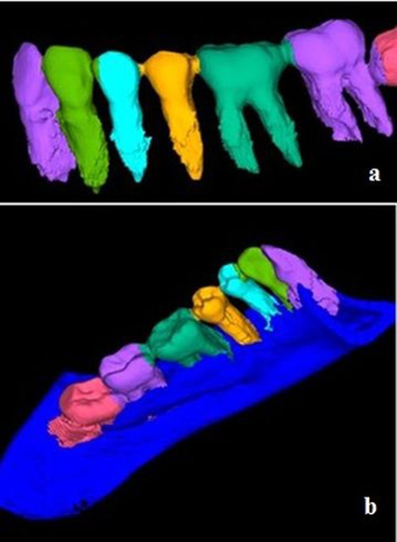
The threshold segmentation creates two volume objects: Dentition and Jaw. The bone tissue no longer needs to be adjusted. The Dentition object may include almost all teeth of the jaw or several teeth; it depends on which area of interest has been selected for processing from the amount of data. Since teeth normally contact at the proximal surfaces, the Dentition object on the processed tomograms represents a single surface without the separation of teeth into individual volume models. Therefore, the next stage of the program is the cutting of 3D Dentition object into individual teeth. The teeth are cut-off by a special program function “virtual scissor” on the contact surfaces (Figure 3c). Before separating, dentists should display a 3D model of Dentition in such a way that the cutting line does not intersect crowns and roots of other teeth. As a result of teeth separation from each other, each tooth will be represented by a different volume object, which can be examined and analysed. It is possible to assign each tooth a number corresponding to the international classification and change the colour for better visualization (Figure 4a). In addition, this mode of cutting can be used to properly remove artefacts caused by the similar density of root cement and alveolar bone from the teeth surface.
Figure 4.
Three-dimensional model of the lower jaw segment. (a) Separated teeth from 32 to 38; (b) separated teeth with jaw.
By completing all image-processing steps of the developed algorithm, it is possible to obtain a 3D model consisting of separate upper or lower jaw and teeth (Figure 4b). The received separate models of teeth can be examined on the monitor by a doctor.
To quantify the 3D reconstruction and to validate the algorithm, we are preparing, in our opinion, the most objective study. It involves the construction of 3D models of individual teeth as a part of dentition in submitted software. Then the teeth, which on certain indications had to be extracted, are being scanned in 3D scanners. Obtained models will be compared with volume objects after program reconstruction. Differences will be used as an ultimate metric for algorithm reliability. At the moment of writing this article, we did not have enough data for a reliable assessment of the results. These will be published in due time. Interim results are quite encouraging.
Conclusion
The developed algorithm for image segmentation of computed tomograms allows separating 3D models of jaws and individual teeth, which significantly increases the diagnostic possibilities of this method of examination. The developed algorithm and the program were tested during image processing of spiral CT and CBCT scanners of different manufacturers with different resolutions and fields of view. The highest quality-rendering results are obtained during image processing by spiral CT, which are explained by higher contrast resolution and lower noise of these images. However, the 3D models of teeth, which are obtained by spiral CT scanners, have a ribbed surface compared with CBCT scanners because of lower spatial resolution. At the same time, a modern level of CBCT scanner development does not allow creation of perfect models of individual teeth without distortion. The CBCT technology development in future will improve the quality of source dental system images and will contribute to creation of exact 3D models of teeth and jaws.
The time required for segmentation strongly depends on the type of CT (multislice or cone beam), the kind of jaw (upper or lower) and the type of scanner. On average, the segmentation time (all steps) in the developed software for multispiral CT of the lower jaw with a full dental arch is about 10–15 min, and up to 20 min for CBCT, while for the upper jaw, processing takes 5–10 min more. This time includes several iterations for the selection of the optimal threshold segmentation.
The proposed software does not require specific skills in information technology and can be easily installed and operated by a dentist themselves immediately at his/her workplace. The developed algorithm and the software can be successfully used with the images obtained from different CT scanners, and the obtained models give the dentist more opportunities at various stages of diagnosis and planning of patients' treatment. For example, they can be of much help for implant shape and size personalization, endodontic treatment optimization and periodontal surgery. Also, the created 3D models can then be used for biomechanical analysis.
Further improvement of 3D segmentation of the teeth and jaws will be carried out by the development of new and by the improvement of old image-processing algorithms as well as by the improvement of X-ray scanners. This primarily concerns noise reduction of images, which were obtained during the CBCT, and by increasing the resolution without increasing the radiation dose.
References
- 1.Scarfe WC, Farman AG. What is cone-beam CT and how does it work? Dent Clin North Am 2008; 52: 707–30. doi: 10.1016/j.cden.2008.05.005 [DOI] [PubMed] [Google Scholar]
- 2.Al-Rawi B, Hassan B, Vandenberge B, Jacobs R. Accuracy assessment of three-dimensional surface reconstructions of teeth from cone beam computed tomography scans. J Oral Rehabil 2010; 37: 352–8. doi: 10.1111/j.1365-2842.2010.02065.x [DOI] [PubMed] [Google Scholar]
- 3.Beers AC, Choi W, Pavlovskaia E. Computer-assisted treatment planning and analysis. Orthod Craniofac Res 2003; 6: 117–25. [DOI] [PubMed] [Google Scholar]
- 4.Barone S, Paoli A, Razionale AV. Creation of 3D multi-body orthodontic models by using independent imaging sensors. Sensors (Basel) 2013; 13: 2033–50. doi: 10.3390/s130202033 [DOI] [PMC free article] [PubMed] [Google Scholar]
- 5.Gao H, Chae O. Individual tooth segmentation from CT images using level set method with shape and intensity prior. Pattern Recognit 2010; 43: 2406–17. [Google Scholar]
- 6.Ji DX, Ong SH, Foong KW. A level-set based approach for anterior teeth segmentation in cone beam computed tomography images. Comput Biol Med 2014; 50: 116–28. doi: 10.1016/j.compbiomed.2014.04.006 [DOI] [PubMed] [Google Scholar]
- 7.Hosntalab M, Aghaeizadeh Zoroofi R, Abbaspour Tehrani-Fard A, Shirani G. Classification and numbering of teeth in multi-slice CT images using wavelet-Fourier descriptor. Int J Comput Assist Radiol Surg 2010; 5: 237–49. doi: 10.1007/s11548-009-0389-8 [DOI] [PubMed] [Google Scholar]
- 8.Yanagisawa R, Sugaya Y, Kasahara S, Omachi S. Tooth shape reconstruction from dental CT images with the region-growing method. Dentomaxillofac Radiol 2014; 43: 20140080. doi: 10.1259/dmfr.20140080 [DOI] [PMC free article] [PubMed] [Google Scholar]
- 9.Liu X, Shi F, Zhang J. Teeth segmentation from CBCT images using deformable triangle mesh model. [In Chinese.] Zhongguo Yi Liao Qi Xie Za Zhi 2011; 35: 414–17. [PubMed] [Google Scholar]
- 10.Duy NT, Lamecker H, Kainmueller D, Zachow S. Automatic detection and classification of teeth in CT data. Med Image Comput Comput Assist Interv 2012; 15: 609–16. [DOI] [PubMed] [Google Scholar]
- 11.Goncharenko V, Tuzikov A. Watershed segmentation with chamfer metric. Lect Notes Comput Sci 2006; 4245: 518–29. [Google Scholar]
- 12.Lloréns R, Naranjo V, López F, Alcañiz M. Jaw tissues segmentation in dental 3D CT images using fuzzy-connectedness and morphological processing. Comput Methods Programs Biomed 2012; 108: 832–43. doi: 10.1016/j.cmpb.2012.05.014 [DOI] [PubMed] [Google Scholar]


