Optical imaging devices have become ubiquitous in our society, and a trend toward their miniaturization has been inexorable. In addition to facilitating portability, miniaturization can enable imaging of targets that are difficult to access. For example, in the biomedical field, miniaturized endoscopes can provide microscopic images of subsurface structures within tissue [1]. Such imaging is generally based on the use of miniaturized lenses, though for extreme miniaturization lensless strategies may be required [2]. One such strategy involves imaging through a single, bare optical fiber by treating it as deterministic mode scrambler [3, 4, 5, 6, 7, 8]. This strategy requires laser illumination and is highly sensitive to fiber bending. We demonstrate an alternative strategy based on a principle of spread-spectrum encoding borrowed from wireless communications [9]. Our strategy enables the imaging of self-luminous (i.e. incoherent) objects with throughput independent of pixel number. Moreover, it is insensitive to fiber bending, contains no moving parts, and is amenable to extreme miniaturization.
The transmission of spatial information through an optical fiber can be achieved in many ways [10, 11]. One example is by modal multiplexing where different spatial distributions of light are coupled to different spatial modes of a multimode fiber. Propagation through the fiber scrambles these modes, but these can be unscrambled if the transmission matrix of the fiber is measured a priori [12, 13]. Such spatio-spatial encoding can lead to high information capacity [14] but suffers from the problem that the transmission matrix is not robust. Any motion or bending of the fiber requires a full recalibration of this matrix [6, 7], which is problematic while imaging. A promising alternative is spatio-spectral encoding, since the spectrum of light propagating through a fiber is relatively insensitive to fiber motion or bending. Moreover, such encoding presumes that the light incident on the fiber is spectrally diverse, or broadband, which is fully compatible with our goal here of imaging self-luminous sources.
Techniques already exist to convert spatial information into spectral information. For example, a prism or grating maps different directions of a light rays into different colors. By placing a miniature grating and lens in front of an optical fiber, directional (spatial) information can be converted into color (spectral) information, and launched into the fiber. Such a technique has been used to perform 1D imaging of transmitting or reflecting [11, 15, 16, 17] or even self-luminous [18, 19] objects, where 2D imaging is then obtained by a mechanism of physical scanning along the orthogonal axis. Alternatively, scanningless 2D imaging with no moving parts has been performed by angle-wavelength encoding [11] or fully spectral encoding using a combination of gratings [20] or a grating and a virtual image phased array (VIPA) [21, 22]. These 2D techniques have only been applied to non-self-luminous objects. Such techniques of spectral encoding using a grating have been implemented in clinical endoscope configurations only recently. To our knowledge, the smallest diameter of such an endoscope is 350μm, partly limited by the requirement of a miniature lens in the endoscope [23].
A property of prisms or gratings is that they spread different colors into different directions. For example, in the case of spectrally encoded endoscopy [17], broadband light from a fiber is collimated by a lens and then spread by a grating into many rays traveling in different directions. Such a spreading of directions defines the field of view of the endoscope. If we consider the inverse problem of detecting broadband light from a self-luminous source using the same grating/lens configuration, we find that because of this property of directional spreading only a fraction of the spectral power from the source is channeled by the grating into the fiber. The rest of the power physically misses the fiber entrance, which plays the role of a spectral slit, and becomes lost. Indeed, if the field of view is divided into M resolvable directions (object pixels), then at best only the fraction 1/M of the power from each pixel is detected. Such a scaling law is inefficient and prevents the scaling of this spectral encoding mechanism to many pixels (a similar problem occurs when using a randomly scattering medium instead of a grating [24, 25]). Given that the power from self-luminous sources is generally limited, then certainly it is desirable to not throw away most of this power.
Our solution to this problem involves using a spectral encoder that 1) does not spread the direction of an incoming ray, 2) imprints a code onto the ray spectrum depending on the ray direction, and 3) this code occupies the full bandwidth of the spectrum. As a result of these properties, the fraction of power that can be detected from any given object pixel is roughly fixed and does not decrease as 1/M. We call our encoder a spread-spectrum encoder (SSE). Indeed, there is a close analogy with strategies used in wireless communication [9]. While the spectral encoding techniques described above that involve gratings perform the equivalent of wavelength-division multiplexing, our technique performs the equivalent of code-division multiplexing (or CDMA).
To minimize the spreading of ray directions, we must identify where this spreading comes from. In the case of a grating it comes from lateral features in the grating structure. A SSE, therefore, should be essentially devoid of lateral features and as translationally invariant as possible. On the other hand, to impart spectral codes, in must produce wavelength-dependent time delays. An example of a SSE that satisfies these conditions is a low finesse Fabry-Perot etalon (FPE). This is translationally invariant and thus does not alter ray directions. Moreover, different wavelengths travelling through the etalon experience different, multiple time delays owing to multiple reflections. These time delays also depend on ray direction, providing the possibility of angle-wavelength encoding. It is important to note that losses through such a device are in the axial (backward) direction only, as opposed to lateral directions. Hence, there is no slit effect as in the case of a grating, meaning that the full spectrum can be utilized for encoding, and losses can be kept to a minimum independent of pixel number. This advantage is akin to the Jacquinot advantage in interferometric spectroscopy [26] (also called the étendue advantage).
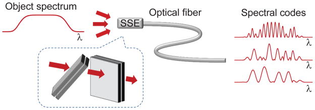
A schematic of our setup is shown in Fig. 1 and described in more detail in Methods and Fig. S1. To simulate an arbitrary angular distribution of self-luminous sources, we made use of a spatial light modulator (SLM) and a lens. The SLM was trans-illuminated by white light from a lamp and the lens’s only purpose was to convert spatial coordinates at the SLM to angular coordinates at the SSE entrance. The SSE here consisted of two FPEs in tandem, each tilted off axis so as to eliminate angular encoding degeneracies about the main optical axis (note: such tilting still preserves translational invariance). In this manner, each 2D ray direction within an angle spanning about 160 mrad, corresponding to our field of view, was encoded into a unique spectral pattern which was then launched into a multimode fiber of larger numerical aperture. The light spectrum at the proximal end of the fiber was then measured with a spectrograph and sent to a computer for interpretation.
Figure 1.

Schematic of method: A self-luminous object with an extended spatial distribution produces light with a broad spectrum. Different spatial portions (pixels) of this object are incident on the entrance of an optical fiber from different directions. A spread-spectrum encoder (SSE) imparts a unique spectral code to each light direction in a power efficient manner. The resulting total spectrum at the output of the fiber is detected by a spectrograph, and image reconstruction is performed by numerical decoding. An example of a SSE is shown in the inset, consisting of two low finesse Fabry-Perot etalons of different free-spectral ranges, tilted perpendicular to each other to encode light directions in 2D.
In our lensless configuration, the optical angular resolution defined by the fiber core diameter was about 3 mrad, which was better (smaller) than the minimum angular pixel size (12 mrad) used to encode our objects. Moreover, these minimum object pixel sizes were large enough to be spatially incoherent, meaning that the spectral signals produced by the pixels could be considered as independent of one another, thus reducing SSE to a linear system. Specifically, for M input pixel elements (ray directions Am), and N output spectral detection elements (Bn), the SSE process can be written in matrix form as B = MA, where each column in M corresponds to the spectral code for its associated object pixel. These spectral codes must be measured in advance prior to any imaging experiment; however, once measured, they are insensitive to fiber motion or bending.
In practice, a distribution of self-luminous sources (object pixels) leads to a superposition of spectral codes weighted according to their respective pixel intensities. A retrieval of this distribution (A) from a measurement of the total output spectrum (B), is formally given by A = M+B, where M+ is the pseudo-inverse of M (see Methods). The reliability and immunity to noise of this inversion depends on the condition of M. Representative spectral codes and singular values of M are shown in Fig. S2. Ideally, the singular values should be as evenly distributed as possible, indicating highly orthogonal spectral codes. In our case, condition numbers of M were on the order of a few hundred, suggesting that our SSEs were not ideal and could be significantly improved in future designs. Nevertheless, despite these high condition numbers, we were able to retrieve 2D images up to 49 pixels in size (see Figs. 2,3, and S3), with weak pixel brightnesses roughly corresponding to that of a dimly lit room.
Figure 2.
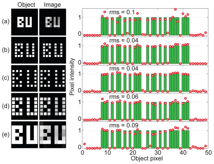
Spatially incoherent, white-light objects in the shape of “BU”, consisting of 49 pixels (7 × 7), are sent through a SSE and launched into a fiber (see Methods). The reconstructed images and pixel values, along with associated rms errors, are displayed for different pixel layouts. In rows (a)–(c), the pixel sizes (powers) are the same, but their separation is increased, leading to better reconstruction (lower rms error). In rows (c)–(e) the pixel separations are the same, but their size is increased until the pixels are juxtaposed. The corresponding increase in pixel power is counterbalanced by a decrease in the contrast of associated spectral codes (due to increased angular diversity per pixel), leading to a net decrease in reconstruction quality (higher rms). The reconstructions were verified to be stable and insensitive to fiber movement or bending (see Fig. S4).
In summary, we have demonstrated a technique to perform imaging of self-luminous objects through a single optical fiber. The technique is based on encoding spatial information into spectral information that is immune to fiber motion or bending. A key novelty of our technique is that encoding is performed over the full spectral bandwidth of the system, meaning that high throughput is maintained independent of the number of resolvable image pixels (as opposed to wavelength-division encoding), facilitating the imaging of self-luminous objects. Encoding is performed by passive optical elements, which, in principle, can be miniaturized to the size of the fiber itself (see Supplementary Information). Applications of this technique include fluorescence or chemiluminescence microendoscopy deep within tissue and with minimal surgical damage. Alternatively, it can be used for ultra-miniaturized imaging of self-luminous or white-light illuminated scenes for remote sensing or surveillance applications.
Methods
Optical layout
The principle of our layout is shown in Fig. 1, and presented in more detail in Fig. S1. An incoherent (e.g. self-luminous) object was simulated by sending collimated white light from a lamp through an intensity transmission spatial light modulator (Holoeye LC2002) with computer-controllable binary pixels. A lens (fθ) converted pixel positions into ray directions, which were then sent through the SSE and directed into an optical fiber (200 μm diameter, 0.39NA). The spectrum at the proximal end of the fiber was recorded with a spectrograph (Horiba CP140-103) featuring a spectral resolution of 2.5 nm as limited by the core diameter of a secondary relay fiber.
SSE construction
Our SSE’s were made of two low finesse FPEs tilted about 45° relative to the optical axis in orthogonal directions relative to each other. The FPEs were made by evaporating thin layers of silver of thickness typically 17 nm onto standard microscope coverslips, manually pressing these together to obtain air gaps of several microns, and glueing with optical cement near the edges of the coverslips.
Calibration and image retrieval
To determine the SSE matrix M prior to imaging, we cycled through each object pixel one by one and recorded the associated spectra (columns of M). Recordings were averaged over 20 measurements with 800 ms spectrograph exposure times. Actual imaging was performed with single spectrograph recordings of B with 800 ms exposure times. Corresponding image pixels Am were reconstructed by least-squares fitting with a non-negativity prior, given by , where Am ≥ 0 ∀m, as provided by the Matlab function lsqnonneg. We note that a baseline background spectrum obtained when all SLM pixels are off was systematically subtracted from all spectral measurements to correct for the limited on/off contrast (about 100:1) of the SLM.
Supplementary Material
Figure 3.
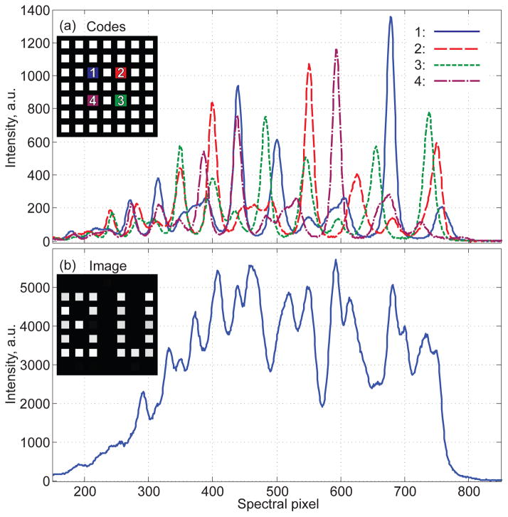
Spectral codes and output spectrum associated with Fig. 2c. (a) Representative spectral codes (columns of M) for four object pixels near center (highlighted by different colors in the inset). (b) The total output spectrum (B) resulting from the weighted sum of spectra from all object pixels, here in the shape of “BU” shown in the inset.
Acknowledgments
We are grateful for financial support from the NIH and from the Boston University Photonics Center.
Footnotes
Author contributions
J.M. and R.B. conceived and designed the experiments. R.B. performed the experiments and analyzed the data. J.M. and R.B. wrote the paper.
Competing financial interests
The authors declare no competing financial interests.
References
- 1.Flusberg BA, Cocker ED, Piyawattanametha W, Jung JC, Cheung ELM, Schnitzer MJ. Fiber-optic fluorescence imaging. Nat Meth. 2005;2:941–950. doi: 10.1038/nmeth820. [DOI] [PMC free article] [PubMed] [Google Scholar]
- 2.Gill PR, Lee C, Lee D-G, Wang A, Molnar A. A microscale camera using direct Fourier-domain scene capture. Opt Lett. 2011;36:2949–2951. doi: 10.1364/OL.36.002949. [DOI] [PubMed] [Google Scholar]
- 3.Di Leonardo R, Bianchi S. Hologram transmission through multimode optical fibers. Opt Express. 2011;19:247–254. doi: 10.1364/OE.19.000247. [DOI] [PubMed] [Google Scholar]
- 4.C̆iz̆már T, Dholakia K. Exploiting multimode waveguides for pure fibre-based imaging. Nat Commun. 2012;3:1027. doi: 10.1038/ncomms2024. [DOI] [PMC free article] [PubMed] [Google Scholar]
- 5.Choi Y, Yoon C, Kim M, Yang T, Fang-Yen C, Dasari R, Lee K, Choi W. Scanner-free and wide-field endoscopic imaging by using a single multimode optical fiber. Phys Rev Lett. 2012;109:203901. doi: 10.1103/PhysRevLett.109.203901. [DOI] [PMC free article] [PubMed] [Google Scholar]
- 6.Papadopoulos IN, Farahi S, Moser C, Psaltis D. Focusing and scanning light through a multimode optical fiber using digital phase conjugation. Opt Express. 2012;20:10583–10590. doi: 10.1364/OE.20.010583. [DOI] [PubMed] [Google Scholar]
- 7.Caravaca-Aguirre AM, Niv E, Conkey DB, Piestun R. Real-time resilient focusing through a bending multimode fiber. Opt Express. 2013;21:12881–12887. doi: 10.1364/OE.21.012881. [DOI] [PubMed] [Google Scholar]
- 8.Mahalati RN, Gu RY, Kahn JM. Resolution limits for imaging through multimode fiber. Opt Express. 2013;21:1656–1668. doi: 10.1364/OE.21.001656. [DOI] [PubMed] [Google Scholar]
- 9.Sklar B. Digital Communications: Fundamentals and Applications. 2. Prentice Hall; 2001. [Google Scholar]
- 10.Yariv A. Three-dimensional pictorial transmission in optical fibers. Appl Phys Lett. 1976;28:88–89. [Google Scholar]
- 11.Friesem AA, Levy U, Silberberg Y. Parallel transmission of images through single optical fibers. Proc IEEE. 1983;71:208–221. [Google Scholar]
- 12.Vellekoop IM, Mosk AP. Focusing coherent light through opaque strongly scattering media. Opt Lett. 2007;32:2309–2311. doi: 10.1364/ol.32.002309. [DOI] [PubMed] [Google Scholar]
- 13.Popoff SM, Lerosey G, Carminati R, Fink M, Boccara AC, Gigan S. Measuring the transmission matrix in optics: an approach to the study and control of light propagation in disordered media. Phys Rev Lett. 2010;104:100601. doi: 10.1103/PhysRevLett.104.100601. [DOI] [PubMed] [Google Scholar]
- 14.Stuart HR. Dispersive multiplexing in multimode optical fiber. Science. 2000;289:281–283. doi: 10.1126/science.289.5477.281. [DOI] [PubMed] [Google Scholar]
- 15.Kartashev AL. Optical systems with enhanced resolving power. Opt Spectrosc. 1960;9:204–206. [Google Scholar]
- 16.Bartelt HO. Wavelength multiplexing for information transmission. Opt Commun. 1978;27:365–368. [Google Scholar]
- 17.Tearney GJ, Webb RH, Bouma BE. Spectrally encoded confocal microscopy. Opt Lett. 1998;23:1152–1154. doi: 10.1364/ol.23.001152. [DOI] [PubMed] [Google Scholar]
- 18.Tai AM. Two dimensional image transmission through a single optical fiber by wavelength-time multiplexing. Appl Opt. 1983;22:3826–3832. doi: 10.1364/ao.22.003826. [DOI] [PubMed] [Google Scholar]
- 19.Abramov A, Minai L, Yelin D. Multiple-channel spectrally encoded imaging. Opt Express. 2010;18:14745–14751. doi: 10.1364/OE.18.014745. [DOI] [PubMed] [Google Scholar]
- 20.Mendlovic D, Garcia J, Zalevsky Z, Marom E, Mas D, Ferreira C, Lohmann AW. Wavelength-multiplexing system for single-mode image transmission. Appl Opt. 1997;36:8474–8480. doi: 10.1364/ao.36.008474. [DOI] [PubMed] [Google Scholar]
- 21.Xiao S, Weiner AM. 2-D wavelength demultiplexer with potential for ≥ 1000 channels in the c-band. Opt Express. 2004;12:2895–2902. doi: 10.1364/opex.12.002895. [DOI] [PubMed] [Google Scholar]
- 22.Goda K, Tsia KK, Jalali B. Serial time-encoded amplified imaging for real-time observation of fast dynamic phenomena. Nature. 2009;458:1145–1149. doi: 10.1038/nature07980. [DOI] [PubMed] [Google Scholar]
- 23.Yelin D, Rizvi I, White WM, Motz JT, Hasan T, Bouma BE, Tearney GJ. Three-dimensional miniature endoscopy. Nature. 2006;443:765. doi: 10.1038/443765a. [DOI] [PubMed] [Google Scholar]
- 24.Kohlgraf-Owens T, Dogariu A. Transmission matrices of random media: means for spectral polarimetric measurements. Opt Lett. 2010;35:2236–2238. doi: 10.1364/OL.35.002236. [DOI] [PubMed] [Google Scholar]
- 25.Redding B, Liew SF, Sarma R, Cao H. Compact spectrometer based on a disordered photonic chip. Nat Photon. 2013;7:746–751. [Google Scholar]
- 26.Jacquinot P. New developments in interference spectroscopy. Rep Prog Phys. 1960;23:267–312. [Google Scholar]
Associated Data
This section collects any data citations, data availability statements, or supplementary materials included in this article.


