

Abstract
Background. The aims of this study were to investigate the ridge contour anterior to the nasopalatine canal, and the difference between the incidences of the nasopalatine canal perforation in dentate and partially edentulous patients by cone-beam computed tomography.
Methods. Cone-beam computed tomography scan images from 72 patients were selected from database and divided into dentate and partially edentulous groups. The configuration of the ridge anterior to the canal including palatal concavity depth, palatal concavity height, palatal concavity angle, bone height coronal to the incisive foramen, and bone width anterior to the canal was measured. A virtual implant placement procedure was used, and the incidences of perforation were evaluated after implant placement in the cingulum position with the long axis along with the designed crown.
Results. Comparing with variable values from dentate patients, the palatal concavity depth and angle were greater by 0.9 mm and 4°, and bone height was shorter by 1.1 mm in partially edentulous patients, respectively. Bone width in edentulous patients was narrower than in dentate patients by 1.2 mm at incisive foramen level and 0.9 mm at 8 mm subcrestal level, respectively. After 72 virtual cylindrical implants (4.1 × 12 mm) were placed, a total of 12 sites (16.7%) showed a perforation and three-fourths occurred in partially edentulous patients. After replacing with 72 tapered implants (4.3 × 13 mm), only 6 implants (8.3%) broke into the canal in the partially edentulous patient group.
Conclusions. The nasopalatine canal may get close to the implant site and the bone width anterior to the canal decreases after the central incisor extraction. The incidence of nasopalatine canal perforation may occur more commonly during delayed implant placement in central incisor missing patients.
Keywords: Alveolar bone, Anterior maxilla, Dental implants, Nasopalatine canal, Cone-beam computed tomography
Introduction
Dental implant restoration has become a very common treatment in dental practices (Chung et al., 2009; Fugazzotto, Vlassis & Butler, 2004; Scheller et al., 1998). In the esthetic zone, the primary goal of implant treatment is to re-establish both esthetics and function (Buser & Von Arx, 2000). As generally accepted, the implant placement is always based on a restorative-driven philosophy (Garber & Belser, 1995). According to this concept, the three-dimensional ideal implant position has been described (Buser, Martin & Belser, 2004; Funato et al., 2007; Grunder, Gracis & Capelli, 2005; Su et al., 2010; Tarnow, Cho & Wallace, 2000). Mesio-distally, a single implant should be at least 1.5 mm away from adjacent root surface (Buser, Martin & Belser, 2004; Grunder, Gracis & Capelli, 2005). Apico-coronally, the implant platform is supposed to be placed 2–4 mm apically to the designed mid-facial gingival margin (Buser, Martin & Belser, 2004; Funato et al., 2007). Bucco-lingually, the implant should be positioned slightly palatal to the incisal edge and 2 mm of buccal bone is recommended (Funato et al., 2007; Grunder, Gracis & Capelli, 2005). Regarding the optimal implant orientation, placement of an implant axis in alignment with the designed crown is recommended in order to fabricate a screw-retained implant crown and prevent from excessive off-axis loading (Chan et al., 2014).
However, in both immediate and delayed implant therapy, the nasopalatine canal (NPC) is often an anatomical limitation for a maxillary central incisor implant placement in an ideal position according to the restorative-driven philosophy. The NPC is a bony channel located posterior to the maxillary central incisors and connects the nasal floor with the oral cavity. The NPC contains the nasopalatine nerve, the terminal branch of descending nasopalatine artery, fibrous connective tissue, fat, and small salivary glands (Keith, 1979; Liang et al., 2009). The relative location of the NPC in the maxilla was previously described by assessing the dimension of the buccal bone plate anterior to this canal in some studies, and a proximity of the NPC to the implant surgical site after tooth extraction was reported (Bornstein et al., 2011; Mardinger et al., 2008; Tözüm et al., 2012). Moreover, placement of implants with invading into the NPC may lead to direct contact of the implant with connective tissue and cause a series of complications, including hemorrhage during operation, short term sensory disturbance postoperatively, non-osseointegration of implant and nasopalatine duct cyst formation (Casado et al., 2008; McCrea, 2014; Mraiwa et al., 2004; Peñarrocha et al., 2014; Takeshita et al., 2013). When the NPC interrupts the central incisor implant placement, more complicated surgical procedure is required and the risk of complications increases.
Through examination of computerized tomography images of 30 American patients, Kraut & Boyden (1998) studied the volumes of the NPC and bone anterior to the canal and reported that approximately 4% NPC will be detrimental to the implant placement. However, the incidence of perforation into the NPC is associated with not only the anatomic morphology, but also the feature of the implant and the three-dimensional implant position. The incidence of perforation into the NPC when a central incisor implant is placed in an ideal position following an optimal axis was not well known yet. In addition, the change of the ridge morphology caused by tooth loss may increase the incidence of perforation has not been assessed. Besides, the feature of the exposure and the risk factors of the perforation have never been analyzed. Whether a tapered implant or a minor adjustment of implant angulation could be beneficial for avoidance of perforation was also not well known.
Cone-beam computed tomography (CBCT) has been widely used in clinical evaluation before implant surgery because of the capability of accurate three-dimension imaging, relative low radiation dose and costs (White, 2008). Moreover, virtual implant placement in CBCT scan images could provide an overall evaluation of implant position and the proximity of the implant to the surrounding anatomic structure (Fortin et al., 2003; Katsoulis, Pazera & Mericske-Stern, 2009). The accuracy of computer-guided template-based implant dentistry was analyzed in previous literature (Schneider et al., 2009). The results showed that the mean horizontal deviation was approximately 1 mm at the entry point and approximately 1.6 mm at the apex. Although the reliability may be insufficient to perform a “blind” implant surgery considering the fine anatomic structure around the implant site, CBCT is still one of the most valuable imaging tools in dentistry. Reasonable accurate three-dimensional anatomic information and the relationship between implant and surrounding anatomical structures can be evaluated thoroughly by observing CBCT scans, and the likelihood of complications could reduce afterwards. The aims of this study were to investigate the ridge contour anterior to the NPC and the difference between the incidences of NPC perforation in dentate and partially edentulous patients by CBCT.
Materials and Methods
Patient selection
This study was approved by the Biomedical Ethics Committee of Peking University School of Stomatology (approval ID PKUSSIRB-201519006). The pre-existing CBCT (Vatech CT, Korea) data selected for this study were performed from January 2011 to July 2014 for treatment planning of implant procedures. Appropriate methodology and sample size were determined by a pilot study and power analysis. The sample size was calculated with α = 0.05 and power = 0.90. It was determined that a sample size of 36 specimens per group (for a total sample of 72) was needed to represent a clinically significant difference in bone width anterior to the NPC.
Patients and images selected for this study had to fulfill the following inclusion criteria: (1) Chinese adults with either full teeth of anterior maxillary sextant or missing one maxillary central incisor in this sextant; (2) the present maxillary anterior teeth without obvious crowding or spacing; (3) no deep (>3 mm) overbite or increased (>3 mm) overjet in the anterior teeth area; (4) at least two pairs of posterior teeth which could be retained with occlusal contact on each side; (5) complete CBCT scanning of premaxilla and NPC with clear images without scattering artifacts. Patients and images were excluded if: (1) both maxillary central incisor were present but the amount of alveolar bone loss exceeded one third of root length; (2) unhealed extraction sockets and the period after extraction was within 6 months; (3) any socket preservation procedures were performed in the missing maxillary central incisor sites; (4) both maxillary central incisors were missing; (5) alveolar ridge height of implant site was less than 14 mm or the ridge width was less than 3.5 mm at the level of 2 mm below the bone crest. Images were assigned into two groups: dentate and partially edentulous groups. When anterior maxillary sextant presented was classified as dentate group, while the edentulous ridge of missing one maxillary central incisor was classified as partially edentulous group. The distributions of age, gender, NPC shape on sagittal slice (Mardinger et al., 2008) and implant site were well matched between two groups, respectively.
Data reconstruction
All images were obtained using a CBCT machine (Vatech CT, Gyeonggi-do, Korea) with standardized routine procedures in the Peking University School of Stomatology by experienced radiologists. The imaging parameters were set at 90 kVp, 7.0 mAs, scan time 24 s, resolution 0.15 mm and a field of view that varied based on the region scanned. The scans included in this study were selected from the database and processed with a measurement software program (Ez3D2009 Premium Ver. 1.2.1.0) in a password-protected computer. The observer examined CBCT images using monitor at a 1,280 × 1,024 screen resolution under room lighting. The distance between display and the observer was approximately 30 cm. The scans were re-oriented so that the premaxilla was bilaterally symmetric and the long axis of the sagittal CBCT slice was determined following the long axis of the designed crown (connecting the bucco-lingual midpoint at the cemento-enamel junction and the point at the incisal edge) of the maxillary central incisor. The data were reconstructed with slices at an interval of 0.5 mm. The luminance and grayscale were adjusted to obtain clear CBCT views.
Configuration of ridge anterior to the NPC
The palatal concavity of the alveolar ridge anterior to the NPC was analyzed by examining the sagittal slices (Fig. 1A) and measuring:
Figure 1. Configuration of ridge anterior to the NPC.

(A) a, the palatal concavity depth (PCD); b, the palatal concavity height (PCH); c, the palatal concavity angulation (PCA); d, the height of the alveolar bone coronal to the NPC (BH). (B) The arrow stands for minimum bone width anterior to the NPC (BW), measured at incisive foramen level, 8 mm and 14 mm below bone crest level, respectively.
-
(1)
The palatal concavity depth (PCD), the distance between the deepest point of the buccal plate on the palatal side and a reference line parallel to the sagittal long axis of the central incisor crown and passing through the labial opening of incisive foramen.
-
(2)
The palatal concavity height (PCH), the distance between the deepest point of the buccal plate on the lingual side and a reference line perpendicular to the sagittal long axis of the central incisor crown and passing through the alveolar bone crest.
-
(3)
The palatal concavity angulation (PCA), the angulation between the line connecting the deepest point of the palatal concavity and the labial opening of incisive foramen and the line parallel to the long axis of the central incisor crown and passing through the deepest point of the palatal concavity.
In addition, the height of the alveolar bone coronal to the NPC (BH) was also recorded by measuring the vertical distance between the alveolar bone crest and the line perpendicular to the sagittal long axis of the central incisor crown and passing through the labial opening of incisive foramen in the midsagittal plane of the NPC (Fig. 1A).
The minimum width of buccal bone plate anterior to the NPC (BW) was measured in the axial view images at three levels: incisive foramen level, 8 mm subcrestal level and 14 mm subcrestal level (Fig. 1B).
Relative location of the NPC and the virtual implant
Seventy-two cylindrical implants (Straumann Bone-Level Implant, 4.1 × 12 mm, Fig. 2) and 72 tapered implants (Nobel Replace Tapered Implant 4.3 × 13 mm, Fig. 2) were placed virtually in the selected maxillary central incisor sites sequentially.
Figure 2. Features of the selected implants.
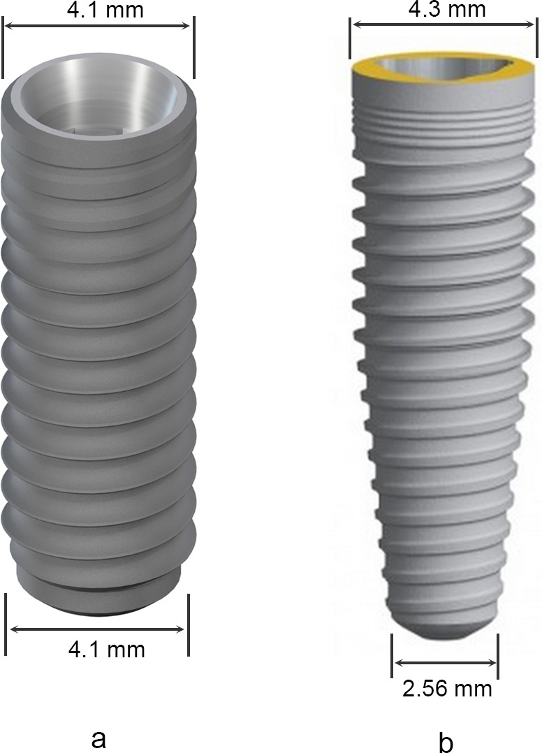
(A) Straumann Bone-Level Implant 4.1 × 12 mm; (B) Nobel Replace Tapered Implant 4.3 × 13 mm.
In the dentate group, each implant was placed in the midsagittal plane of selected maxillary central incisor mesio-distally. Bucco-lingually, the most lingual point of the implant platform was located at the cingulum of the central incisor. Apico-coronally, the implant platform was placed 2 mm below the crestal level. The sagittal long axis of the implant was parallel to the central incisor crown (Figs. 3A–3C).
Figure 3. Three-dimensional location of virtual implant in dentate patients (A–C) and partially edentulous patients (D–F).

(A) and (D) mesio-distal location in dentate and partially edentulous group; (B) and (E) bucco-lingually, the implant platform was placed at the cingulum of the future restoration in both dentate and partially edentulous group; (C) and (F) apico-coronally, the implant platform was located 2 mm below the alveolar bone crest in both groups.
In the partially edentulous group, each implant was placed in the center of the edentulous site mesio-distally. Bucco-lingually, the implant platform was also placed at the cingulum region (Chan et al., 2014). The details were present as follows: connecting the most prominent points of the two lateral incisors or the two canines on their palatal side to draw a reference line and measuring the distance between the cingulum of the natural contralateral central incisor at its most palatal point and the reference line, and then the most palatal point of the implant platform was placed labial to the reference line by the same distance. Apico-coronally, the location of the implant platform was the same as that of the dentate group. The sagittal long axis of the implant was parallel to the contralateral central incisor crown (Figs. 3D–3F).
After each virtual implant was placed, whether the implant penetrating through the interior wall of the NPC was assessed in the sagittal and axial views slice by slice. For the NPC perforation cases caused by cylindrical implants, the position of the implant platform was kept unchanged and the embedded direction was rotated distally and labially by a minor angulation (5°and 10°), respectively. The size and the location of each perforation were measured in the sagittal and axial view images, which included its length, depth, area and the distance between the most coronal point of the perforation and the alveolar bone crest (Fig. 4).
Figure 4. Description of nasopalatine canal (NPC) perforation in both sagittal slice and axial slice.

a, length of exposure; b, distance between the alveolar crest and the perforation (location of perforation); c, the depth of the exposure; d, the area of the exposure.
All measurements were conducted by two examiners (XJ and WH). The inter- and intraexaminer agreement was determined by comparing two repeated measurements at 20 randomly chosen sites taken 1-week apart.
Statistical analysis
All statistical analysis was performed using a statistical package (IBM, SPSS Statistics 19.0). The inter- and intraexaminer agreement was determined using a t test. All measurements were presented as means ± standard deviations (SDs). The occurrence of the NPC perforation was expressed as the number of sites and the percentage of the number of sites divided by the total number of sites. The PCD, PCH, PCA, BH and BW were compared between dentate group and partially edentulous group by Mann–Whitney U test. The chi-square test was used to compare the incidences of perforation between groups, genders and sides. Univariate and multivariate logistic regression analyses were performed to identify risk factors associated with the NPC perforation with the significance level at α = 0.05.
Results
A total of 703 subjects were screened and 72 subjects (54 males and 18 females) were selected for this study. The mean age was 45.6 years, with a range of 28–64 years of age. Each group consisted of 36 subjects. The age, gender and implant site were well matched between the dentate group and the partially edentulous group, respectively. The distribution of NPC shape recorded on sagittal plane did not show statistically significant differences between groups (Table 1). The intra-examiner and inter-examiner agreements were 0.94 and 0.87, respectively (p > 0.05).
Table 1. General characteristics of tested subjects.
| Total (n = 72) | Dentate group (n = 36) | Partially edentulous group (n = 36) | p value | |
|---|---|---|---|---|
| Age (mean ± SD) | 45.6 ± 8.8 | 45.5 ± 9.0 | 45.6 ± 8.8 | 0.906 |
| Gender (n) | ||||
| Male | 54 | 27 | 27 | |
| Female | 18 | 9 | 9 | 1.000 |
| Implant site (n) | ||||
| Right central incisor | 30 | 15 | 15 | |
| Left central incisor | 42 | 21 | 21 | 1.000 |
| Canal shapes (n) | ||||
| Cylindrical | 29 | 17 | 12 | |
| Funnel-like | 17 | 6 | 11 | |
| Hourglass-like | 15 | 9 | 6 | |
| Banana-like | 11 | 4 | 7 | 0.290 |
The measuring results of configuration of ridge anterior to the NPC are shown in Table 2. A total of 54 ridges (75.0%) showed a palatal concavity in sagittal views. The mean and SD of PCD, PCH and PCA values were 1.8 ± 1.7 mm, 14.3 ± 7.3 mm and 8.6 ± 6.5°, respectively. The incisive foramen was located at 5.9 ± 2.3 mm below the alveolar bone crest. The mean and SD values of BWs at the incisive foramen level, 8 mm and 14 mm related to the subcrestal level were 6.0 ± 1.7 mm, 6.3 ± 1.5 mm and 6.9 ± 1.9 mm, respectively. Results of comparisons of ridge configuration between the dentate group and the partially edentulous group were also listed in Table 2 and shown in Fig. 5. There was statistically significant difference between the mean PCD values of the dentate group and the partially edentulous group (1.4 ± 1.4 mm vs. 2.3 ± 1.9 mm, p = 0.036). In addition, the mean PCA values of the dentate group and the partially edentulous group were 6.6° and 10.6°, respectively (p = 0.022). The distance between the incisive foramen and the bone crest was significant closer in the partially edentulous group than in the dentate group by 1.1 mm approximately (p = 0.022). At the incisive foramen level, the mean BW was statistically significantly thinner in the partially edentulous group than the dentate group, 5.4 ± 2.5 mm and 6.6 ± 1.1 mm, respectively (p = 0.013). Furthermore, the mean BW values measured at 8 mm subcrestal level of the dentate group and the partially edentulous group were 6.7 mm and 5.8 mm, respectively (p = 0.028). There was no statistically significant difference between groups of the PCH and BW values at 14 mm subcrestal level (p > 0.05).
Table 2. Ridge configuration and comparison results (mean ± SD).
| Variable | Dental status | Gender | |||||
|---|---|---|---|---|---|---|---|
| Total (n = 72) | Dentate (n = 36) | Partially edentulous (n = 36) | p | Male (n = 54) | Female (n = 18) | p | |
| Palatal concavity | |||||||
| PCD (mm) | 1.8 ± 1.7 | 1.4 ± 1.4 | 2.3 ± 1.9 | 0.036 | 1.9 ± 1.7 | 1.6 ± 1.8 | 0.349 |
| PCH (mm) | 14.3 ± 7.3 | 13.9 ± 7.8 | 14.8 ± 6.8 | 0.539 | 14.9 ± 7.7 | 12.6 ± 5.8 | 0.275 |
| PCA (°) | 8.6 ± 6.5 | 6.6 ± 5.9 | 10.6 ± 6.5 | 0.022 | 8.4 ± 6.3 | 9.1 ± 7.2 | 0.758 |
| BH (mm) | 5.9 ± 2.3 | 6.5 ± 1.9 | 5.4 ± 2.5 | 0.022 | 5.9 ± 2.4 | 5.8 ± 1.7 | 0.958 |
| BW (mm) | |||||||
| Incisive foramen level | 6.0 ± 1.7 | 6.6 ± 1.1 | 5.4 ± 2.0 | 0.013 | 6.2 ± 1.7 | 5.4 ± 1.6 | 0.040 |
| 8 mm subcrestal level | 6.3 ± 1.5 | 6.7 ± 1.2 | 5.8 ± 1.6 | 0.028 | 6.5 ± 1.4 | 5.5 ± 1.4 | 0.004 |
| 14 mm subcrestal level | 6.9 ± 1.9 | 7.0 ± 1.6 | 6.7 ± 2.1 | 0.401 | 7.1 ± 2.0 | 6.4 ± 1.3 | 0.141 |
Notes.
- PCD
- palatal concavity depth
- PCH
- palatal concavity height
- PCA
- palatal concavity angulation
- BH
- bone height coronal to the canal
- BW
- bone width anterior to the canal
Figure 5. Comparison of ridge configuration anterior to the nasopalatine canal (NPC) between dentate and partially edentulous patients.

The red line stands for the ridge contour of partially edentulous patients.
Table 2 also illustrated the comparison results between genders. At the incisive foramen level, the mean BW was statistically significantly greater in male subjects compared with female subjects by 0.8 mm (p = 0.040). In addition, the mean BWs measured at 8 mm subcrestal level of the male and the female subjects were 6.5 mm and 5.5 mm, respectively (p = 0.004). The PCD, PCH, BH values were greater in male subjects, although the statistically significant difference did not exist (p > 0.05). When virtual cylindrical implants (4.1 × 12 mm) were placed, a total of 12 sites (16.7%) showed invading and perforation (Table 3). Three cases of them occurred in the dentate group (8.3%) while other nine cases occurred in the partially edentulous group (25.0%). The incidence of perforation was much higher in the partially edentulous group, although the statistically significant difference did not exist (p = 0.058). With respect to the implant site, the incidence of perforation was statistically significantly higher in the right central incisor site than in the left central incisor site, 33.3% and 4.8%, respectively (p = 0.001). The occurrence of perforation did not show statistically significant differences between genders (p > 0.05). In the axial view images, all the perforations were located at the mesio-palatal site of the virtual implant. Furthermore, the depth and the area of exposure were 0.7 ± 0.6 mm (range = 0.2–2.1 mm) and 1.0 ± 1.3 mm2 (range = 0.2–4.7 mm2), respectively. In the sagittal view images, the exposure located at 8.5 ± 3.5 mm below the alveolar bone crest, with a range of 2.3 mm–12.1 mm, and the length of the exposure was 5.1 ± 3.4 mm, with a range of 1.6 mm–12.0 mm.
Table 3. Frequency distribution of perforation with different implant type.
| Group | Implants (number) | Number of perforations (number and percent) | |
|---|---|---|---|
| Cylindrical 4.1 × 12 mm | Tapered 4.3 × 13 mm | ||
| Dental status | |||
| Dentate group | 36 | 3 (8.3%) | 0 (0.0%)** |
| Partially edentulous group | 36 | 9 (25.0%) | 6 (16.7%)** |
| Implant site | |||
| Right central incisor site | 30 | 10 (33.3%)* | 5 (16.7%)*** |
| Left central incisor site | 42 | 2 (4.8%)* | 1 (2.4%)*** |
| Gender | |||
| Male | 54 | 7 (13.0%) | 3 (5.6%) |
| Female | 18 | 5 (27.8%) | 3 (16.7%) |
| Total | 72 | 12 (16.7%) | 6 (8.3%) |
Notes.
Statistically significant difference exists between implant sites with cylindrical implant (p = 0.001).
Statistically significant difference exists between dentate and partially edentulous groups with tapered implant (p = 0.011).
Statistically significant difference exists between implant sites with tapered implant (p = 0.031).
After replacing the cylindrical implants with the tapered implants (4.3 × 13 mm), a total of 6 implants (8.3%) entered into the NPC, which all belonged to the partially edentulous group (Table 3). The incidence of perforation with the selected tapered implant was statistically significantly different between the dentate and partially edentulous groups (p = 0.011). Besides, five out of six perforations occurred in the right central incisor sites, and the statistically significant difference existed between different sides (p = 0.031). The location of the exposure was at the 6.2 ± 3.2 mm below the alveolar bone crest. The length, depth and area of the exposure were 5.4 ± 3.1 mm, 0.8 ± 0.6 mm and 1.3 ± 1.7 mm2, respectively.
The numbers of perforation sites was reduced to 4 (5.6%) and 2 (2.8%) by tilting the embedded direction of the cylindrical implant distal-apically by 5° and 10°, respectively. After the embedded direction was rotated labial-apically by the same degrees (5° and 10°), the incidence of perforation decreased to 8.3% and 4.2%, respectively. The changes of incidences of perforation, as well as the features of exposure after a minor adjustment of cylindrical implant angulation, were presented in Table 4.
Table 4. Incidence of perforation after implant angulation adjustment.
| Embedded direction | Number (%) | Location (mm) | Length (mm) | Depth (mm) | Area (mm2) |
|---|---|---|---|---|---|
| Axis of restoration | 12 (16.7%) | 8.5 ± 3.5 | 5.1 ± 3.4 | 0.7 ± 0.6 | 1.0 ± 1.3 |
| Distal by 5° | 4 (5.6%) | 5.4 ± 3.7 | 5.5 ± 2.0 | 0.8 ± 0.4 | 3.9 ± 4.9 |
| Distal by 10° | 2 (2.8%) | 2.4 ± 0.1 | 6.6 ± 2.1 | 1.1 ± 0.2 | 2.3 ± 0.7 |
| Labial by 5° | 6 (8.3%) | 6.8 ± 3.7 | 5.9 ± 3.9 | 0.9 ± 0.7 | 1.5 ± 1.9 |
| Labial by 10° | 3 (4.2%) | 5.3 ± 4.9 | 8.2 ± 5.1 | 1.2 ± 0.9 | 2.4 ± 2.4 |
The multivariate logistic regression analysis revealed that the PCD was a statistically significant risk factor of perforation (OR 4.332; 95% CI [1.596–11.760]; p = 0.004). Implant placement in the left central incisor site (OR 0.087; 95% CI [0.010–0.783]; p = 0.029) and BW measured at 8 mm below the alveolar bone crest (OR 0.273; 95% CI [0.111–0.671]; p = 0.005) were two protective factors appeared in the last model (Table 5).
Table 5. Multivariate logistic regression of factors affecting the NPC perforation.
| Variables | β | OR | 95% CI | p value |
|---|---|---|---|---|
| Left central incisor implant site | −2.446 | 0.087 | 0.010–0.783 | 0.029 |
| BW measured at 8 mm below crest | −1.299 | 0.273 | 0.111–0.671 | 0.005 |
| PCD | 1.466 | 4.332 | 1.596–11.760 | 0.004 |
| Constant | 1.974 | 7.200 | 0.329 |
Notes.
- NPC
- nasopalatine canal
- BW
- bone weight anterior to the canal
- PCD
- palatal concavity depth
Discussion
Chan and colleagues (2014) used CBCT imaging technique and found that a buccal concavity of ridge always existed anterior to the maxillary central incisor. The mean value of buccal concavity depth was reported to have mean of 3.42 mm, and it was associated with the occurrence of buccal plate fenestration. However, few studies have provided information regarding the palatal concavity and its relationship with the NPC during implant placement procedure. In the present study, the perforations of the NPC by the virtual implants were located at the labia-distal side only. Therefore, with an obvious palatal concavity, that means the NPC is located relatively at the labial side, may increase the risk of implant entering and damaging the neurovascular bundles within the NPC. In this study, 75% of ridges were present with a palatal concavity. More importantly, the palatal concavity depth was a statistically significant risk factor of NPC perforation. Therefore, not only the location of the incisive foramen, but also the trend of the NPC configuration should be carefully evaluated by CBCT during diagnostic procedure and treatment plan for implant therapy.
Bone dimensions anterior to the NPC are important factors for successful implant placement. In previous studies, bone dimensions were measured at crestal, middle, and (or) the most apical point of the canal in the midsagittal plane of the NPC with the reference line perpendicular to the maxillary plane or the sagittal long axis of the canal (Bornstein et al., 2011; Tözüm et al., 2012). A mean bone width of 7.17 ± 1.49 mm has been reported in a multicenter study (Tözüm et al., 2012). However, the implant is rarely placed in the midsagittal plane of the NPC, and also not involving the nasal part of the canal. In addition, the embedded direction may be different from the direction of measurement mentioned above. As a result, the data obtained by previous measuring methods might not reflect the implant condition accurately. In this study, the bone width anterior to the NPC was first measured in the axial view images at three levels: the incisive foramen level, 8 mm below the alveolar bone crestal level, and 14 mm below the crestal level. The incisive foramen level is where the NPC prevents the implant from placement procedure at the early beginning. The 8 mm and 14 mm below the bone crestal levels may represent the middle level and the apex level of the virtual implant selected in this study, respectively. In addition, the measuring direction was perpendicular to embedded direction of implant, that is, the sagittal long axis of the restoration. As a result, the measuring results of the present study would reflect the real implant condition with better accuracy. In the present study, the mean bone width anterior to the NPC was 6.0 and 6.3 mm at the incisive foramen level and 8 mm below the alveolar crest level, respectively. The results were slightly narrower than the bone width (7.17 mm) reported by Tözüm et al. (2012).
The incidence of NPC perforation during the maxillary central incisor implant procedure was evaluated using virtual implant placements in CBCT images. Using a cylindrical central incisor implant (4.1 × 12 mm) placed in the cingulum position with the long axis following that of its restoration, the incidence of NPC perforation was revealed to be 16.7% and significant higher than a previous study reported in using computerized tomography scanning images of American patients (Kraut & Boyden, 1998). The increased versatility of both latest CBCT and software could provide a more accurate and precise measurement of the relationship between implant and anatomical structures. Considering that the incidence of NPC perforation is associated with not only the anatomic morphology, but also the feature of implant and the three-dimensional implant position, the results present in this study may reflect the clinical implant condition more accurately. In addition, different racial sampling may have some effects on the skeletal development. Another study of our research team showed that the mean closest distance between the NPC and the apex of the central incisor root were 3.88 mm in axial CBCT images (X Jia et al., 2015, unpublished data), much closer than the mean distance of 5.22 mm reported by Chatriyanuyoke et al. (2012). The relatively lower values of the closest distances implied that insertion of implants into the NPC might be more likely to occur in Chinese patients.
The absence of maxillary central incisors affected some dimension changes of bony structure and incidences of NPC perforation. The results of comparison between the dentate and partially edentulous group revealed that, the PCD and PCA were statistically significantly greater in the partially edentulous group by 0.9 mm and 4°, respectively, although the distribution of NPC shape recorded on sagittal plane did not show statistically significant differences between groups. Mardinger et al. (2008) also found that the bucco-lingual NPC diameter was wider along the degree of ridge resorption. In the present study, it is implied that a closer proximity of NPC to implant site might be presented after tooth loss for a while with wound healed. In addition, bone width anterior to the canal and the bone height coronal to the canal were greater in dentate subjects in the present study by 1.2 mm and 1.1 mm respectively, mainly due to the alveolar bone remodeling after tooth loss (Araújo & Lindhe, 2005; Schropp et al., 2003). Other studies reported similar results regarding the change of bone width after tooth loss as the present study (Mardinger et al., 2008; Tözüm et al., 2012). Considering the ridge modeling after tooth loss, including the change of PCD, PCA, BH and BW as mentioned before, it would be no surprise that the incidence of NPC perforation was significantly higher in the partially edentulous group than the dentate group (25.0% and 8.3% after cylindrical implant placement; 16.7% and 0.0% after tapered implant placement). It is indicated that delayed implant placement in the maxillary central incisor site may require more care to avoid NPC perforation (Table 3). Another thing to keep in mind is that, in this study, one maxillary central incisor was present in the partially edentulous group for reference. Considering that loss of both central incisors may affect the ridge resorption, the potential of NPC perforation during delayed implant placement might increase in patients without both maxillary central incisors.
The results showed that the gender influenced the alveolar bone dimensions anterior to the NPC (Table 2). The mean BW values measured at the incisive foramen level and at 8 mm subcrestal level were significantly greater in men compared with women by 0.8 mm and 1.0 mm, respectively (p < 0.05). Our results correlates well with some other studies. Güncü et al. (2013) reported that buccal bone thickness were greater in male subjects. Chatriyanuyoke et al. (2012) also found that men had larger amounts of bone between the NPC and the MCIR sockets than women. Considering the results of comparisons of anatomic structures between genders, it would not be a surprise that insertion of implants into the NPC was more likely to occur in women, although the difference of incidence was not statistically significant, maybe due to insufficient sample size.
Another interesting finding was that the perforation usually occurred in the right central incisor site. The multivariate logistic regression analysis also revealed that the implant site was associated with the occurrence of NPC perforation (Table 5). This corresponds with the results of our preliminary study about the location of the NPC leaning on the right side at both the incisive foramen level and the apical level (X Jia et al., 2015, unpublished data).
The location, length, depth, and area of perforation are important information for implant placement. In the axial view images, all the perforations were located at the mesio-palatal side of the implant. However, in the sagittal view images, the perforation could occur at any part of implant (2.3–12.1 mm below the bone crest). The mean distance between the exposure and the crest was 8.5 mm in the present study, which meant that the perforation usually occurred at the mid-root level of the implant. A mean length of exposure of 5.1 mm indicated that the NPC perforation could not be ignored. However, on the other hand, the depth of exposure was only 0.7 mm on average, which meant that a tapered implant or a minor adjustment of implant angulation might be beneficial to prevent NPC from being invaded. In this study, tapered implant platform (4.3 × 13 mm) was selected and larger than the cylindrical implant in diameter by 0.2 mm. However, the diameter of the tapered implant will be narrowed to 4.1 mm at about 3.4 mm below the implant platform level, and only proximately 2.56 mm in diameter at the implant apical level, narrower than the cylindrical implant by approximately 1.5 mm (Fig. 2). Considering the relative shallow depth of exposure after cylindrical implant placement, a significant decrease of the incidence of perforation from 16.7% to 8.3% will be achieved if a cylindrical implant is replaced with a tapered implant (4.3 × 13 mm). A minor change of embedded direction was also beneficial for decreasing NPC perforation percentage from 16.7% down to 8.3% to 2.8% (Table 4). However, before the adjustment of implant angulation, practitioners should keep the proximity of adjacent lateral incisor to the implant site and the existing buccal concavity in mind. The distance between the implant apex and the adjacent root surface should not be too close and should not be less than 1.5 mm separation after rotating the implant to the distal, while the buccal plate fenestration is always the major factor to be considered during rotating the implant to the labial.
However, neither selected a tapered implant nor a minor adjustment (less than 10°) of implant angulation can avoid NPC perforation successfully in some cases. Therefore, it is recommended to take full analysis of the NPC using CBCT at the time of implant treatment planning with consideration of individual differences. The results in this study suggested that other appropriate features of implant, for example a shorter implant or a narrower implant, or a greater embedded angle that departed from the axis of the restoration might be selected to avoid perforation in some cases. For the cases that the implant may invade into the NPC inevitably, the debridement or the displacement of the neurovascular bundle in conjunction with the guided bone regeneration were proposed to prevent direct contact of implant surface with the neurovascular bundle and to provide adequate bone (Artzi et al., 2000; Peñarrocha et al., 2014; Rosenquist & Nyström, 1992; Verardi & Pastagia, 2012). These methods could significantly improve the condition of implant placement, but more long-term studies with large samples are necessary.
The limitation of this study is that the results are based on virtual analysis. When taking the findings of this study for reference, the practitioners should keep some consideration in mind, including the accuracy of CBCT scans, the features of the implant, and the surgical experience. Further clinical trial is required to clarify this issue. In addition, unassisted socket healing cases were adopted in the present study, although alveolar ridge preservation has become a key component of contemporary clinical dentistry (Avila-Ortiz et al., 2014). However, the effects of socket grafting and preservation procedures on the contour changes of the NPC are almost unknown. There is a need to evaluate the impact of specific alveolar ridge preservation procedures on the contour changes of the NPC and perforation incidences during implant placement in future.
Conclusions
Within the limits of this study, it can be concluded that the NPC may get close to the implant site after the central incisor extraction, and the bone width anterior to the canal may also reduce. The NPC perforations may occur more commonly in partially edentulous patients for delayed implant placement and in the right central incisor site. The right central incisor site with narrower bone width measured at 8 mm below the crest and a deep palatal concavity are associated with the common occurrence of NPC perforation during implant placement. A minor adjustment of implant angulation or using a tapered implant may be beneficial for preventing from NPC perforation.
Supplemental Information
Funding Statement
This study was supported by key program of clinical specialty, National Ministry of Health (2010–2012), and Capital Medical Development and Research Fund, PRC (2011-4025-04). The funders had no role in study design, data collection and analysis, decision to publish, or preparation of the manuscript.
Additional Information and Declarations
Competing Interests
The authors declare there are no competing interests.
Author Contributions
Xueting Jia, Wenjie Hu and Huanxin Meng conceived and designed the experiments, performed the experiments, analyzed the data, contributed reagents/materials/analysis tools, wrote the paper, prepared figures and/or tables, reviewed drafts of the paper.
Human Ethics
The following information was supplied relating to ethical approvals (i.e., approving body and any reference numbers):
Biomedical Ethics Committee of Peking University School of Stomatology (approval ID PKUSSIRB-201519006).
References
- Araújo & Lindhe (2005).Araújo MG, Lindhe J. Dimensional ridge alterations following tooth extraction. An experimental study in the dog. Journal of Clinical Periodontology. 2005;32:212–218. doi: 10.1111/j.1600-051X.2005.00642.x. [DOI] [PubMed] [Google Scholar]
- Artzi et al. (2000).Artzi Z, Nemcovsky CE, Bitlitum I, Segal P. Displacement of the incisive foramen in conjunction with implant placement in the anterior maxilla without jeopardizing vitality of nasopalatine nerve and vessels: a novel surgical approach. Clinical Oral Implants Research. 2000;11:505–510. doi: 10.1034/j.1600-0501.2000.011005505.x. [DOI] [PubMed] [Google Scholar]
- Avila-Ortiz et al. (2014).Avila-Ortiz G, Elangovan S, Kramer KW, Blanchette D, Dawson DV. Effect of alveolar ridge preservation after tooth extraction: a systematic review and meta-analysis. Journal of Dental Research. 2014;93:950–958. doi: 10.1177/0022034514541127. [DOI] [PMC free article] [PubMed] [Google Scholar]
- Bornstein et al. (2011).Bornstein MM, Balsiger R, Sendi P, von Arx T. Morphology of the nasopalatine canal and dental implant surgery: a radiographic analysis of 100 consecutive patients using limited cone-beam computed tomography. Clinical Oral Implants Research. 2011;22:295–301. doi: 10.1111/j.1600-0501.2010.02010.x. [DOI] [PubMed] [Google Scholar]
- Buser, Martin & Belser (2004).Buser D, Martin W, Belser UC. Optimizing esthetics for implant restorations in the anterior maxilla: anatomic and surgical considerations. The International Journal of Oral & Maxillofacial Implants. 2004;19(Suppl):43–61. [PubMed] [Google Scholar]
- Buser & Von Arx (2000).Buser D, Von Arx T. Surgical procedures in partially edentulous patients with ITI implants. Clinical Oral Implants Research. 2000;11(Suppl 1):83–100. doi: 10.1034/j.1600-0501.2000.011S1083.x. [DOI] [PubMed] [Google Scholar]
- Casado et al. (2008).Casado PL, Donner M, Pascarelli B, Derocy C, Duarte ME, Barboza EP. Immediate dental implant failure associated with nasopalatine duct cyst. Implant Dentistry. 2008;17:169–175. doi: 10.1097/ID.0b013e3181776c52. [DOI] [PubMed] [Google Scholar]
- Chan et al. (2014).Chan HL, Garaicoa-Pazmino C, Suarez F, Monje A, Benavides E, Oh TJ, Wang HL. Incidence of implant buccal plate fenestration in the esthetic zone: a cone beam computed tomography study. International Journal of Oral and Maxillofacial Implants. 2014;29:171–177. doi: 10.11607/jomi.3397. [DOI] [PubMed] [Google Scholar]
- Chatriyanuyoke et al. (2012).Chatriyanuyoke P, Lu CI, Suzuki Y, Lozada JL, Rungcharassaeng K, Kan JY, Goodacre CJ. Nasopalatine canal position relative to the maxillary central incisors: a cone beam computed tomography assessment. Journal of Oral Implantology. 2012;38:713–717. doi: 10.1563/AAID-JOI-D-10-00106. [DOI] [PubMed] [Google Scholar]
- Chung et al. (2009).Chung WE, Rubenstein JE, Phillips KM, Raigrodski AJ. Outcomes assessment of patients treated with osseointegrated dental implants at the University of Washington Graduate Prosthodontic Program, 1988 to 2000. The International Journal of Oral & Maxillofacial Implants. 2009;24:927–935. [PubMed] [Google Scholar]
- Fortin et al. (2003).Fortin T, Bosson JL, Coudert JL, Isidori M. Reliability of preoperative planning of an image-guided system for oral implant placement based on 3-dimensional images: an in vivo study. The International Journal of Oral & Maxillofacial Implants. 2003;18:886–893. [PubMed] [Google Scholar]
- Fugazzotto, Vlassis & Butler (2004).Fugazzotto PA, Vlassis J, Butler B. ITI implant use in private practice: clinical results with 5,526 implants followed up to 72+ months in function. The International Journal of Oral & Maxillofacial Implants. 2004;19:408–412. [PubMed] [Google Scholar]
- Funato et al. (2007).Funato A, Salama MA, Ishikawa T, Garber DA, Salama H. Timing, positioning, and sequential staging in esthetic implant therapy: a four-dimensional perspective. International Journal of Periodontics & Restorative Dentistry. 2007;27:313–323. [PubMed] [Google Scholar]
- Garber & Belser (1995).Garber DA, Belser UC. Restoration-driven implant placement with restoration-generated site development. Compendium of Continuing Education in Dentistry. 1995;16 796, 798–802. 804. [PubMed] [Google Scholar]
- Grunder, Gracis & Capelli (2005).Grunder U, Gracis S, Capelli M. Influence of the 3-D bone-to-implant relationship on esthetics. International Journal of Periodontics & Restorative Dentistry. 2005;25:113–119. [PubMed] [Google Scholar]
- Güncü et al. (2013).Güncü GN, Yıldırım YD, Yılmaz HG, Galindo-Moreno P, Velasco-Torres M, Al-Hezaimi K, Al-Shawaf R, Karabulut E, Wang HL, Tözüm TF. Is there a gender difference in anatomic features of incisive canal and maxillary environmental bone? Clinical Oral Implants Research. 2013;24:1023–1026. doi: 10.1111/j.1600-0501.2012.02493.x. [DOI] [PubMed] [Google Scholar]
- Katsoulis, Pazera & Mericske-Stern (2009).Katsoulis J, Pazera P, Mericske-Stern R. Prosthetically driven, computer-guided implant planning for the edentulous maxilla: a model study. Clinical Implant Dentistry and Related Research. 2009;11:238–245. doi: 10.1111/j.1708-8208.2008.00110.x. [DOI] [PubMed] [Google Scholar]
- Keith (1979).Keith DA. Phenomenon of mucous retention in the incisive canal. Journal of Oral Surgery. 1979;37:832–834. [PubMed] [Google Scholar]
- Kraut & Boyden (1998).Kraut RA, Boyden DK. Location of incisive canal in relation to central incisor implants. Implant Dentistry. 1998;7:221–225. doi: 10.1097/00008505-199807030-00010. [DOI] [PubMed] [Google Scholar]
- Liang et al. (2009).Liang X, Jacobs R, Martens W, Hu Y, Adriaensens P, Quirynen M, Lambrichts I. Macro- and micro-anatomical, histological and computed tomography scan characterization of the nasopalatine canal. Journal of Clinical Periodontology. 2009;36:598–603. doi: 10.1111/j.1600-051X.2009.01429.x. [DOI] [PubMed] [Google Scholar]
- Mardinger et al. (2008).Mardinger O, Namani-Sadan N, Chaushu G, Schwartz-Arad D. Morphologic changes of the nasopalatine canal related to dental implantation: a radiologic study in different degrees of absorbed maxillae. Journal of Periodontology. 2008;79:1659–1662. doi: 10.1902/jop.2008.080043. [DOI] [PubMed] [Google Scholar]
- McCrea (2014).McCrea SJ. Nasopalatine duct cyst, a delayed complication to successful dental implant placement: diagnosis and surgical management. Journal of Oral Implantology. 2014;40:189–195. doi: 10.1563/AAID-JOI-D-12-00011. [DOI] [PubMed] [Google Scholar]
- Mraiwa et al. (2004).Mraiwa N, Jacobs R, Van Cleynenbreugel J, Sanderink G, Schutyser F, Suetens P, Van Steenberghe D, Quirynen M. The nasopalatine canal revisited using 2D and 3D CT imaging. Dentomaxillofac Radiol. 2004;33:396–402. doi: 10.1259/dmfr/53801969. [DOI] [PubMed] [Google Scholar]
- Peñarrocha et al. (2014).Peñarrocha D, Candel E, Guirado JL, Canullo L, Peñarrocha M. Implants placed in the nasopalatine canal to rehabilitate severely atrophic maxillae: a retrospective study with long follow-up. Journal of Oral Implantology. 2014;40:699–706. doi: 10.1563/AAID-JOI-D-12-00145. [DOI] [PubMed] [Google Scholar]
- Rosenquist & Nyström (1992).Rosenquist JB, Nyström E. Occlusion of the incisal canal with bone chips. A procedure to facilitate insertion of implants in the anterior maxilla. International Journal of Oral and Maxillofacial Surgery. 1992;21:210–211. doi: 10.1016/S0901-5027(05)80220-6. [DOI] [PubMed] [Google Scholar]
- Scheller et al. (1998).Scheller H, Urgell JP, Kultje C, Klineberg I, Goldberg PV, Stevenson-Moore P, Alonso JM, Schaller M, Corria RM, Engquist B, Toreskog S, Kastenbaum F, Smith CR. A 5-year multicenter study on implant-supported single crown restorations. The International Journal of Oral & Maxillofacial Implants. 1998;13:212–218. [PubMed] [Google Scholar]
- Schneider et al. (2009).Schneider D, Marquardt P, Zwahlen M, Jung RE. A systematic review on the accuracy and the clinical outcome of computer-guided template-based implant dentistry. Clinical Oral Implants Research. 2009;20(Suppl 4):73–86. doi: 10.1111/j.1600-0501.2009.01788.x. [DOI] [PubMed] [Google Scholar]
- Schropp et al. (2003).Schropp L, Wenzel A, Kostopoulos L, Karring T. Bone healing and soft tissue contour changes following single-tooth extraction: a clinical and radiographic 12-month prospective study. International Journal of Periodontics & Restorative Dentistry. 2003;23:313–323. [PubMed] [Google Scholar]
- Su et al. (2010).Su H, Gonzalez-Martin O, Weisgold A, Lee E. Considerations of implant abutment and crown contour: critical contour and subcritical contour. International Journal of Periodontics & Restorative Dentistry. 2010;30:335–343. [PubMed] [Google Scholar]
- Takeshita et al. (2013).Takeshita K, Funaki K, Jimbo R, Takahashi T. Nasopalatine duct cyst developed in association with dental implant treatment: a case report and histopathological observation. Journal of Oral and Maxillofacial Pathology. 2013;17(2):319. doi: 10.4103/0973-029X.119761. [DOI] [PMC free article] [PubMed] [Google Scholar]
- Tarnow, Cho & Wallace (2000).Tarnow DP, Cho SC, Wallace SS. The effect of inter-implant distance on the height of inter-implant bone crest. Journal of Periodontology. 2000;71:546–549. doi: 10.1902/jop.2000.71.4.546. [DOI] [PubMed] [Google Scholar]
- Tözüm et al. (2012).Tözüm TF, Güncü GN, Yıldırım YD, Yılmaz HG, Galindo-Moreno P, Velasco-Torres M, Al-Hezaimi K, Al-Sadhan R, Karabulut E, Wang HL. Evaluation of maxillary incisive canal characteristics related to dental implant treatment with computerized tomography: a clinical multicenter study. Journal of Periodontology. 2012;83:337–343. doi: 10.1902/jop.2011.110326. [DOI] [PubMed] [Google Scholar]
- Verardi & Pastagia (2012).Verardi S, Pastagia J. Obliteration of the nasopalatine canal in conjunction with horizontal ridge augmentation. Compendium of Continuing Education in Dentistry. 2012;33:116–120. 122. [PubMed] [Google Scholar]
- White (2008).White SC. Cone-beam imaging in dentistry. Health Physics. 2008;95:628–637. doi: 10.1097/01.HP.0000326340.81581.1a. [DOI] [PubMed] [Google Scholar]
Associated Data
This section collects any data citations, data availability statements, or supplementary materials included in this article.