Abstract
Background:
Several factors are known to influence osseous union of femoral neck fractures. Numerous clinical studies have reported different results, hence with different recommendations regarding treatment of Pauwels III fractures: femoral neck fractures with a more vertically oriented fracture line. The current study aimed to analyze biomechanically whether this fracture poses a higher risk of nonunion.
Objectives:
To analyze the influence of one designated factor, authors believe that a computerized fracture model, using a finite element Finite Element Method (FEM), may be essential to negate the influence of other factors. The current study aimed to investigate a single factor, i.e. orientation of the fracture line toward a horizontal line, represented by Pauwels classification. It was hypothesized that a model with a vertically oriented fracture line maintaining parity of all other related factors has a higher stress at the fracture site, which would delay fracture healing. This result can be applicable to other types of pinning.
Patients and Methods:
The finite element models were constructed from computed tomography data of the femur. Three fracture models, treated with pinning, were constructed based on Pauwels classification: Type I, 30° between the fracture line and a horizontal line; Type II, 50°; and Type III, 70°. All other factors were matched between the models. The Von Mises stress and principal stress distribution were examined along with the fracture line in each model.
Results:
The peak Von Mises stresses at the medial femoral neck of the fracture site were 35, 50 and 130 MPa in Pauwels type I, II, and III fractures, respectively. Additionally, the peak Von Mises stresses along with the fracture site at the lateral femoral neck were 140, 16, and 8 MPa in Pauwels type I, II, and III fractures, respectively. The principal stress on the medial femoral neck in Pauwels type III fracture was identified as a traction stress, whereas the principal stress on the lateral femoral neck in Pauwels type I fracture was a compression stress.
Conclusions:
The most relevant finding was that hook pinning in Pauwels type III fracture may result in delayed union or nonunion due to significantly increased stress of a traction force at the fracture site that works to displace the fracture. However, in a Pauwels type I fracture, increased compression stress contributes to stabilize it. Surgeons are recommended not to treat Pauwels type III femoral neck fractures by pinning.
Keywords: Femoral Neck Fractures, Finite Element Analysis, Vertical
1. Background
Femoral neck fractures are a major health problem in aging societies such as Japan. Minimally displaced fractures are usually managed with internal fixation to hasten early rehabilitation. Despite good clinical results with fracture healing, high rates of delayed union or nonunion are reported (1). Therefore, it is necessary to determine the factors causing this complication.
Multiple factors that have the potential for delayed union or nonunion, such as fracture displacement, osteoporosis, age of the patient at injury, vertically oriented fracture line towards a horizontal line (Pauwels type III), experience of the surgeon, number of screws (two or three), parallelism of the screws, the presence of screws in each “quadrant” of the femoral head, reduction gap at the fracture site, and alignment after reduction of the fracture, were previously reported (2). Consequently, since a number of factors seem to be involved, it may be difficult to prove by a clinical study whether a single factor is a critical cause. Previous clinical studies revealed a wide range of results regarding the influence of Pauwels type III on fracture healing (3, 4).
2. Objectives
To analyze the influence of one designated factor, authors believe that a computerized fracture model, using a Finite Element Method (FEM), may be essential to negate the influence of other factors.
The current study aimed to investigate a single factor, i.e. orientation of the fracture line toward a horizontal line, represented by Pauwels classification. It was hypothesized that a model with a vertically oriented fracture line maintaining parity of all other related factors has a higher stress at the fracture site, which would delay fracture healing. This result can be applicable to other types of pinning.
3. Patients and Methods
3.1. Finite Element Method
Finite element models were constructed by computed tomography (CT) data consisting of femoral cortical and cancellous bone maps obtained from a healthy individual without any femoral impairment (female; age 90 years). The patient was informed that data from the case would be submitted for publication, and she signed a letter of consent. Axial CT images at intervals of 0.6mm were taken in the neutral unloaded position. To simplify calculations, all soft tissues, including capsules and ligaments, were excluded. The models were converted to digital imaging and communications in medicine files (DICOM; Pro/Engineer Wildfire v2.0; Parametric Technology Corporation, Waltham, MA) and constructed. dimensions of Hansson pins (Stryker Osteosynthesis, Selzach, Switzerland) were manually measured. The computer models were subsequently imported into ANSYS v12.0 (ANSYS Inc., Canonsburg, PA), engineering simulation software. All materials were assumed to be homogeneous, isotropic, and linear elastic. The mechanical properties of Young’s modulus and Poisson’s ratio were obtained from the literature (5) (Table 1). Young’s moduli for cortical bone, cancellous bone, and the implant were 13.3, 0.44 and 110 GPa, respectively. Moduli for cancellous bone varied in accordance with the location on the femur; namely head, neck, or shaft. Poisson’s ratio was assigned as 0.3 for both cortical and cancellous bones. A weight-bearing force of 1500 N was applied to the hemispherical surface of the femoral head. An abductor muscle force of 1000 N was exerted to the insertion of the abductor musculature on the lateral and superior surfaces of the greater trochanter.
Table 1. Material Properties: Young’s Modulus and Poisson’s Ratio.
| Component | Young R, GPa | Poisson R | Density, Kg/m3 |
|---|---|---|---|
| Cortex | 13.3 | 0.3 | 1880 |
| Cancellous | 0.3 | 500 | |
| Head | 0.44 | ||
| Neck | 0.32 | ||
| Shaft | 0.15 | ||
| Hook ping | 110 | 0.3 | 4620 |
The FE models, with approximately 128,000 elements and 29,000 nodes, were created using ANSYS Academic Research v11.0 Workbench (ANSYS Inc.). Linear (quadratic ansatz) structural solids with tetrahedral shapes were used. The distal end of the bone was constrained in all directions (6° of freedom). The femoral neck fractures to be studied were osteotomized virtually without creating a gap between fracture fragments.
To accurately capture the stresses and strains at the interface of the bone and implant, all contacts between the two fracture fragments and the implant were considered. The coefficient of friction was zero for pairing bone-bone, and 0.1 for implant-bone (5).
3.2. Computation
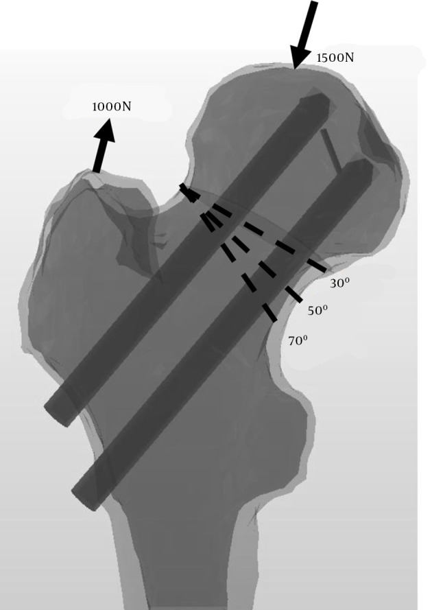
Three 3D fracture models with different fracture line angles based on Pauwels classification were constructed as follows: type I, 30° between the fracture line and a horizontal line; type II, 50°; and type III, 70° as vertical oriented fracture line (Figure 1). Computations were performed and analyzed by a commercial nonlinear finite element code, ABAQUS 6.11-2 (Simulia Inc., Vélizy-Villacoublay Cedex, France).
Figure 1. Fimite Element Method (FEM) Construction of Three Fracture Models.

A, Type I, 30° between the fracture line and the horizontal line; B, Type II, 50°; and C, Type III, 70°. An abductor muscle force and a weight-bearing force were exerted.
The FE models provided a means to solve clinical problems by predicting stress distribution throughout the structures of interest. The Von Mises stress distribution along with the fracture line was analyzed to identify the location and magnitude of the maximum stress in each model. Since the traction to be prone caused treatment failure (6), the principal stress was analyzed to predict whether the stress at the fracture site was due to compression or traction.
4. Results
Stress distribution on the whole proximal femur including cortex and cancellous bone, and implants were examined. Authors focused on stress along with the fracture line of the femoral neck region, medially calcar bone and laterally femoral neck, considering the influence on fracture healing.
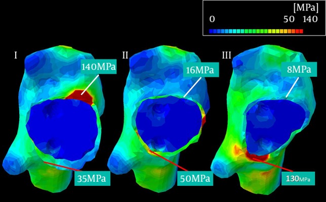
The peak Von Mises stresses along with the fracture site at the medial femoral neck were 35 MPa, 50 MPa, and 130 MPa in Pauwels type I, II, and III fractures, respectively (Figure 2). The peak Von Mises stresses along with the fracture site at the lateral femoral neck were 140 MPa, 16 MPa, and 8 MPa in Pauwels type I, II, and III fractures, respectively.
Figure 2. Viewed From the Top After Removal of the Femoral Head, Showing the Von Mises Stress Distribution.

The peak stresses at the medial cortex (red lines) were 35, 50 and 130 MPa in Pauwels type I, II, and III fractures, respectively.
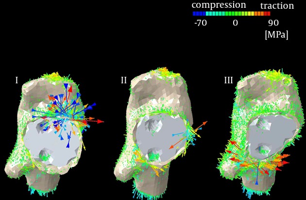
The principal stress was analyzed to clarify the type of stress observed in peak levels of Von Mises stress distribution, especially in significantly elevated spots of the peak Von Mises stresses. This result demonstrated that a traction stress at the medial femoral neck in Pauwels type III fracture causes displacement, or delayed healing of fractures, whereas a compression stress at the lateral femoral neck in Pauwels type I fracture helps to stabilize the fracture and accelerate fracture healing (Figure 3). This may contradict the belief that the single leg standing condition generates tensile stresses in the lateral femur and compressive stresses in the medial femur (7).
Figure 3. Illustrating the Principal Stresses.

In Pauwels type I fracture, compression stress was elevated, contributing to stabilization of the fracture (multiple blue arrows). In Pauwels type III fracture, traction stress resulted in displacement of the fracture (multiple red arrows).
5. Discussion
Simulation studies are helpful to predict and demonstrate the influence of specific factors in a given system. Since clinical studies may be influenced by several controlled and uncontrolled variables, FE models can effectively focus on a single factor, at the same time negate the effects of other variables.
The most important finding of the current study was that hook pinning in Pauwels type III fracture results in significantly increased stress at the fracture site, which may result in delayed union or nonunion. Several articles regarding the high risk of delayed union or nonunion in Pauwels type III fractures are reported. Liporace et al. (8) reported 19% nonunion postoperatively, and Stankewich et al. (9) concluded that pinning was not recommended in Pauwels type III fracture in their cadaver study. However, Yang et al. (10) conducted a statistical study on femoral neck fracture healing rates and found no significant relationship between the fracture angle and the occurrence of nonunion or late segmental collapse, which many surgeons agree with (3, 4, 11). There are several reasons for these conflicting results. First, factors relevant to nonunion are multifactorial, factors such as individual differences between bone structure, fracture reduction, precise positioning of the pins among the femoral neck or head, fracture impaction, osteoporosis, two parallel pins, and vertical angle of the fracture line (2, 12). Second, the Pauwels type III fracture pattern is rarely encountered, making it difficult to obtain a statistically significant conclusion (8). Third, surgeons may misinterpret radiographs between types II and III fractures (13). To address these problems, authors conducted a biomechanical study that equalized all parameters except for the fracture line angle towards the horizontal line, based on Pauwels classification.
The current study results revealed the occurrence of elevated stress at the medial femoral neck in Pauwels type III fracture. The principal stress causing displacement in a Pauwels type III fracture was a traction force. On the other hand, increased stress on the lateral side of the fracture line in a Pauwels type I fracture consisted of stress compression, contribution to stabilize the fracture and promotion of higher screw purchase strength. A possible explanation of the traction stress in Pauwels type III fracture may be that the calcar region failed to effectively serve as a fulcrum during loading, since this region is located proximally beyond the fracture line. Thus, the constructs may have consistently failed due to proximal fragment shifting or tilting into a varus position (14). This would coincide with the idea that a more vertically oriented fracture surface (thus a greater angle) would lose stability, and vice versa.
The current study had its limitations. First, soft tissues such as the joint capsule, ligaments, and periosteum were excluded from the analysis. Second, simulation of static loading was only in one direction, which may not sufficiently substitute for complex loading that may occur in activities such as walking (8). Third, a particular limitation of the bone model is that the actual macroscopic property of cancellous bone, which is orthotropic, was not taken into account (i.e. isotropic and heterogeneous properties were assumed both for cortical and cancellous bones).
The current biomechanical study was not a panacea. However, the present study clarified that the types of Pauwels fractures should be treated with hook pins. In the current FEM study, Pauwels type I or II fractures could be sufficiently treated with them. In contrast, since Pauwels type III fractures demonstrated a high risk of displacement in the current FEM study, treatment with them is not recommended. Authors believe that the obtained result can be applicable to other types of pinning, like three cannulated screws. Hence, further comparative studies with biomechanical models are required to identify appropriate implants for Pauwels type III fractures (15).
Footnotes
Authors’ Contributions:Mitsuaki Noda organized the whole research program. Masayasu Takahashi also conducted the biomechanical study. Yasuhiro Saegusa, with abundant knowledge for hip, contributed to give comments. Daichi Tezuka, Kazuhiko Adachi and Kazuya Naoi from department of mechanical engineering, performed biomechanical analysis.
References
- 1.Estrada LS, Volgas DA, Stannard JP, Alonso JE. Fixation failure in femoral neck fractures. Clin Orthop Relat Res. 2002;(399):110–8. doi: 10.1097/00003086-200206000-00013. [DOI] [PubMed] [Google Scholar]
- 2.Toh EM, Sahni V, Acharya A, Denton JS. Management of intracapsular femoral neck fractures in the elderly; is it time to rethink our strategy? Injury. 2004;35(2):125–9. doi: 10.1016/s0020-1383(02)00422-9. [DOI] [PubMed] [Google Scholar]
- 3.Parker MJ, Dynan Y. Is Pauwels classification still valid? Injury. 1998;29(7):521–3. doi: 10.1016/s0020-1383(98)00118-1. [DOI] [PubMed] [Google Scholar]
- 4.van Embden D, Roukema GR, Rhemrev SJ, Genelin F, Meylaerts SA. The Pauwels classification for intracapsular hip fractures: is it reliable? Injury. 2011;42(11):1238–40. doi: 10.1016/j.injury.2010.11.053. [DOI] [PubMed] [Google Scholar]
- 5.Simpson DJ, Brown CJ, Yettram AL, Procter P, Andrew GJ. Finite element analysis of intramedullary devices: the effect of the gap between the implant and the bone. Proc Inst Mech Eng H. 2008;222(3):333–45. doi: 10.1243/09544119JEIM337. [DOI] [PubMed] [Google Scholar]
- 6.Schwarzkopf R, Dong NN, Fetto JF. Finite element analysis of femoral neck stress in relation to pelvic width. Bull NYU Hosp Jt Dis. 2011;69(4):292–7. [PubMed] [Google Scholar]
- 7.Fox MJ, Scarvell JM, Smith PN, Kalyanasundaram S, Stachurski ZH. Lateral drill holes decrease strength of the femur: an observational study using finite element and experimental analyses. J Orthop Surg Res. 2013;8:29. doi: 10.1186/1749-799X-8-29. [DOI] [PMC free article] [PubMed] [Google Scholar]
- 8.Liporace F, Gaines R, Collinge C, Haidukewych GJ. Results of internal fixation of Pauwels type-3 vertical femoral neck fractures. J Bone Joint Surg Am. 2008;90(8):1654–9. doi: 10.2106/JBJS.G.01353. [DOI] [PubMed] [Google Scholar]
- 9.Stankewich CJ, Chapman J, Muthusamy R, Quaid G, Schemitsch E, Tencer AF, et al. Relationship of mechanical factors to the strength of proximal femur fractures fixed with cancellous screws. J Orthop Trauma. 1996;10(4):248–57. doi: 10.1097/00005131-199605000-00005. [DOI] [PubMed] [Google Scholar]
- 10.Yang JJ, Lin LC, Chao KH, Chuang SY, Wu CC, Yeh TT, et al. Risk factors for nonunion in patients with intracapsular femoral neck fractures treated with three cannulated screws placed in either a triangle or an inverted triangle configuration. J Bone Joint Surg Am. 2013;95(1):61–9. doi: 10.2106/JBJS.K.01081. [DOI] [PubMed] [Google Scholar]
- 11.Weinrobe M, Stankewich CJ, Mueller B, Tencer AF. Predicting the mechanical outcome of femoral neck fractures fixed with cancellous screws: an in vivo study. J Orthop Trauma. 1998;12(1):27–36. doi: 10.1097/00005131-199801000-00005. discussion 36-7. [DOI] [PubMed] [Google Scholar]
- 12.Schipper IB, Bresina S, Wahl D, Linke B, Van Vugt AB, Schneider E. Biomechanical evaluation of the proximal femoral nail. Clin Orthop Relat Res. 2002;(405):277–86. doi: 10.1097/00003086-200212000-00035. [DOI] [PubMed] [Google Scholar]
- 13.Bartonicek J. Pauwels' classification of femoral neck fractures: correct interpretation of the original. J Orthop Trauma. 2001;15(5):358–60. doi: 10.1097/00005131-200106000-00009. [DOI] [PubMed] [Google Scholar]
- 14.Tan V, Wong KL, Born CT, Harten R, DeLong WJ. Two-screw femoral neck fracture fixation: a biomechanical analysis of 2 different configurations. Am J Orthop (Belle Mead NJ). 2007;36(9):481–5. [PubMed] [Google Scholar]
- 15.Aminian A, Gao F, Fedoriw WW, Zhang LQ, Kalainov DM, Merk BR. Vertically oriented femoral neck fractures: mechanical analysis of four fixation techniques. J Orthop Trauma. 2007;21(8):544–8. doi: 10.1097/BOT.0b013e31814b822e. [DOI] [PubMed] [Google Scholar]


