Abstract
The purpose of this study was to determine whether cone beam digital models are as accurate as OrthoCAD (Cadent, Inc, Carlstadt, NJ) digital models for the purposes of orthodontic diagnosis and treatment planning. Digital records of 30 subjects were retrospectively reviewed, and the digital models were obtained as OrthoCAD and InVivoDental (San Jose, CA) digital models. Seven parameters indicating linear measurements from predetermined landmarks were measured and analyzed. The analysis of variance and Bland and Altman Analysis were used to compare and evaluate measurements made from the study models generated from cone beam computed tomography (CBCT) and InVivoDental software. The mean difference between the maxillary InVivoDental models and the maxillary OrthoCAD models ranged from −0.57 to 0.44 mm. The analysis of variance for repeated measures (P < 0.001) was applied to all data obtained from the CBCT and OrthoCAD models. The results indicated a mean score of 35.12 and 35.12 mm, respectively. The mean difference of all values was −7.93 × 10⁻³ mm. The range of these values at the 95% confidence interval was −0.14 and 0.12 mm for the lower and upper limits, respectively. The results were not statistically significant for both groups. The Bland and Altman analysis was also applied to the data. In the maxilla, the results indicated that the mean difference between InVivoDental and OrthoCAD was −0.01 ± 1.24 mm. The range of the analysis indicated a spread of −2.40 mm and +2.40 mm. In the mandible, the results indicated that the mean difference between InVivoDental and OrthoCAD was −0.01 ± 1.21 mm. The range of the analysis indicated a spread of −2.36 mm and +2.37 mm. The results showed that the linear measurements obtained from CBCT image casts indicated a good level of accuracy when compared with OrthoCAD models. The accuracy was considered adequate for initial diagnosis and treatment planning in orthodontics.
High-quality orthodontic records are necessary for accurate orthodontic diagnosis. Each orthodontist has a preference for certain records that they deem most informative, but most clinicians would agree that the minimum records include extraoral and intraoral photographs, dental models, intraoral and/or panoramic radiographs, and cephalometric radiographs.1 Combining these records with a clinical examination provides diagnostic information to properly diagnose and treatment plan an orthodontic malocclusion. As with all aspects of the orthodontic profession, technological advances have led to vast improvements in these diagnostics tools, the most recent of which is the advent of digital technology.2,3
As many aspects of people’s personal lives are converting to digital, there has been a move for orthodontic offices to do so as well. More and more clinical practices are transitioning to electronic dental records. Everything from medical histories and progress notes to radiographs and models are now available in a digital format.4,5 This format is particularly advantageous when considering the huge storage space required for traditional plaster casts. Digital models eliminate the need for large storage rooms and their associated expenses.4–8
The predominant method for obtaining digital models is by taking an impression. Some examples of models created from impressions are OrthoCAD (Cadent, Inc, Carlstadt, NJ) and e-Models (Geodigm, Inc, Chanhassen, MN). The impressions are taken at the orthodontist’s office with a high-quality alginate or polyvinyl siloxane material and mailed to the company. The impressions are then poured to produce a plaster equivalent, which is scanned with a proprietary camera or laser into a computer. The resulting digital model is then available for download by the orthodontist from the company’s Web site. Each company provides the orthodontist with proprietary software for viewing and evaluating the models.4,5,7,8
Recently, enhancements in technology have led to digital models being created from cone beam computerized tomography (CBCT) scans. In most instances, the orthodontist uploads the CBCT file (Digital Imaging and Communications in Medicine, DICOM file) through a company’s Web site. Technicians then generate the digital model with their proprietary software and “post” the model file for download. The orthodontist can analyze the models with viewing software. With this technology, the models are embedded in the CBCT image, so all anatomical structures captured during the scan are visible, for example the roots of the teeth, the temporomandibular joints, bone heights, and impacted teeth. The orthodontist can also examine just the teeth without the other structures and evaluate them with or without model bases.9
Cone beam technology is the latest advancement in dental radiography, so that generating models from CBCT scans is the logical next step in the digitization of orthodontic offices.10 Obviously, digital models can replace plaster models only if they are shown to be as accurate for the purposes of orthodontic diagnosis. Many studies addressing the accuracy of digital models from impressions have been performed. The most recent study showed that OrthoCAD digital models are as accurate as traditional plaster models for the purposes of orthodontic diagnosis.11
The purpose of the present study was to determine if cone beam digital models are as accurate as OrthoCAD digital models for the purposes of orthodontic diagnosis and treatment planning.
Materials and Methods
Subjects
The digital records of 30 subjects were retrospectively reviewed, and the digital models were obtained.
The inclusion criteria included the following:
OrthoCAD models obtained by impressions at the initial examination as part of the routine records appointment;
baseline CBCT images captured at the University of Texas Dental Branch—Houston Orthodontic Department as part of the routine records appointment; and
all permanent dentition had to be present.
Imaging Device
The CBCT device used was the Sirona Galileos (Bensheim, Germany). The Galileos X-ray detector receives cone-shaped Conebeam radiation beams, which result in 200 individual exposures from a 14-second cycle in 220° segment. Volume dimensions of 15 × 15 × 15 cm3 capture an image at a high level of detail. The technology also allows for small region close-up views at double the detail without an additional scan. The large dental volume ranges from the bridge of the nose to the tip of the chin and the mandibular joints. The voxel size ranged from 0.15 to 0.30 mm. The image reconstruction time is approximately 4.5 minutes.
InVivoDental Digital Models
The CBCT images were uploaded to commercially available software, InVivoDental by Anatomage (Anatomage, San Jose, CA) via the company’s Web site. Each CBCT image underwent a process of digital reformatting which included volume rendering and image conversion. After the images were converted to 3D digital models by their computer technicians, the models were posted on their Web site for download.
Digital Models from Impressions
To obtain the OrthoCAD models, upper and lower impressions were taken with Identic (Dux Dental USA) alginate, and bite registrations were recorded with poly vinyl siloxane material (Blue Moose, Parkell, Inc, Edgewood, NY). Impressions with bite registrations were then disinfected, placed in a sealed plastic bag, and mailed via next day airmail to OrthoCAD Corporation (Cadent, Inc, Carlstadt, NJ). Once received, OrthoCAD created the digital models and posted them on their Web site for download.
Parameters Measured
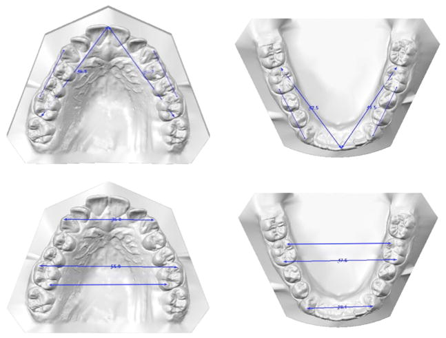
To objectively compare the dimensions of the models from the 2 companies (InVivoDental and OrthoCAD), 7 measurements were taken on each upper and lower model. The digital models by Anatomage were measured with the use of their proprietary software, InVivoDental, and the OrthoCAD models were measured by the use of the OrthoCAD proprietary software, OrthoCAD. Measurements were made in millimeters and the exact anatomical landmarks are outlined in Figure 1 and Table 1.
Figure 1.
Diagrammatic representation of linear measurements from landmark points.
Table 1.
Landmark Definitions on Digital Casts
| Maxillary cast measurements | |
| URDML6 | Distal of the upper right first molar at the central groove to the midline at the level of the mesioincisal line angle of the upper right central incisor |
| ULDML6 | Distal of the upper left first molar at the central groove to the midline at the level of the mesioincisal line angle of the upper left central incisor |
| UR3R6 | Cusp tip of the upper right cuspid to the mesiobuccal cusp tip of the upper right first molar |
| UL3L6 | Cusp tip of the upper left cuspid to the mesiobuccal cusp tip of the upper left first molar |
| U66MB | Mesiobuccal cusp tip of the upper right first molar to the same point on the upper left first molar |
| U66DL | Distolingual cusp tip of the upper right first molar to the same point on the upper left first molar |
| U33 | Cusp tip of the upper right cuspid to the same point on the upper left cuspid |
| Mandibular cast measurements | |
| LRDML6 | Distal of the lower right first molar at the central groove to the midline at the level of the mesioincisal line angle of the lower right central incisor |
| LLDML6 | Distal of the lower left first molar at the central groove to the midline at the level of the mesioincisal line angle of the lower left central incisor |
| LR3R6 | Cusp tip of the lower right cuspid to the mesiobuccal cusp tip of the lower right first molar |
| LL3L6 | Cusp tip of the lower left cuspid to the mesiobuccal cusp tip of the lower left first molar |
| L66MB | Mesiobuccal cusp tip of the lower right first molar to the same point on the lower left first molar |
| L66DL | Distolingual cusp tip of the lower right first molar to the same point on the lower left first molar |
| L33 | Cusp tip of the lower right cuspid to the same point on the lower left cuspid |
The following linear measurements were made:
from the distal of the upper and lower first molars at the central groove to the midline at the level of the mesioincisal line angle of the central incisor on the ipsilateral side;
from the cusp tip of the upper and lower cuspids to the mesiobuccal cusp tip of the ipsilateral first molars on both the right and left sides;
from the mesiobuccal cusp tip of the upper and lower first molars to the same point on the contralateral first molars;
from the distolingual cusp tip of the upper and lower first molars to the same point on the contralateral first molars; and
from the cusp tip of the upper and lower cuspids to the same point on the contralateral cuspids. Figure 1 depicts the linear measurements.
Measurements were carried out by 2 operators in this study. Ten study models measured were compared and the mean differences of the measurements were tabulated with a paired t test. The results of the 2 operators were not significantly different (P < 0.05).
Statistical Analysis
Analysis of variance (ANOVA) for repeated measures was used and within-subjects contrasts were computed. The assumptions of the ANOVA for repeated measures model were evaluated and not violated. The within-subject factors were the 7 measurements (listed previously and shown in Table 1), 2 imaging modalities (InVivoDental and OrthCAD), and 2 jaws (maxilla and mandible). If the within-subject contrasts showed no statistically significant difference, Bland and Altman’s method was used to assess measurement agreement obtained from the 2 software platforms (InVivoDental and OrthoCAD).12
Results
The following results were obtained and presented in Tables 2 and 3.
Table 2.
Mean Differences of the Paired Parameters for Maxillary Model Measurements in Millimeters
| Differences Between Pairs | Mean | SD Deviation | 95% Confidence Interval of the Difference
|
|
|---|---|---|---|---|
| Lower | Upper | |||
| InvURDML6—OrtURDML6 | −0.06 | 0.41 | −0.21 | 0.09 |
| InvULDML6—OrtULDML6 | 0.25 | 0.70 | −0.01 | 0.51 |
| InvUR3R6—OrtUR3R6 | −0.12 | 0.75 | −0.40 | 0.16 |
| InvUL3L6—OrtUL3L6 | 0.03 | 0.61 | −0.20 | 0.25 |
| InvU66MB—OrtU66MB | 0.44 | 2.05 | −0.32 | 1.21 |
| InvU66DL—OrtU66DL | −0.57 | 2.02 | −1.33 | 0.18 |
| InvU33—OrtU33 | −0.01 | 0.75 | −0.29 | 0.27 |
Table 3.
Mean Differences of the Paired Parameters for Mandibular Model Measurements in mm
| Differences Between Pairs | Mean | SD | 95% Confidence Interval of the Difference
|
|
|---|---|---|---|---|
| Lower | Upper | |||
| InvLRDML6—OrtLRDML6 | 0.13 | 0.71 | −0.13 | 0.40 |
| InvLLDML6—OrtLLDML6 | 0.22 | 0.76 | −0.06 | 0.51 |
| InvLR3R6—OrtLR3R6 | 0.03 | 1.45 | −0.51 | 0.57 |
| InvLL3L6—OrtLL3L6 | 0.08 | 1.013 | −0.29 | 0.46 |
| InvL66MB—OrtL66MB | 0.28 | 1.06 | −0.12 | 0.68 |
| InvL66DL—OrtL66DL | −0.62 | 1.58 | −1.21 | −0.03 |
| InvL33—OrtL33 | −0.20 | 1.48 | −0.76 | 0.35 |
Inv, InVivodent; Ort, OrthoCad.
Maxillary and Mandibular Cast Measurements
The mean difference between the InVivoDental models and the OrthoCAD models ranged from −0.57 to 0.44 mm. The mean difference between the InVivoDental models and the OrthoCAD models ranged from −0.62 to 0.22 mm.
ANOVA Analysis for Repeated Measures
The ANOVA for repeated measures (P < 0.001) was applied to all data obtained from the maxillary and mandibular InVivoDental and OrthoCAD models. In both the maxilla and mandible, the results indicated a mean score of 35.12 mm and 35.12 mm for InVivoDental and OrthoCAD, respectively. The mean difference of all values was −7.93 × 10⁻³ mm. The range of these values at the 95% confidence interval was −0.14 and 0.12 mm for the lower and upper limits, respectively. The results were not statistically significant for both groups.
Bland and Altman’s Analysis
The mean differences of all data in the maxillary and mandibular models from the InViVoDental and OrthoCAD models were analyzed using the Bland and Altman’s Analysis. This was done to determine if a good statistical correlation existed between the study models measurements obtained from the 2 digital formats.
In the maxilla, the results indicated that the mean difference between InVivoDental and OrthoCAD was −0.01 ± 1.24 mm. The range of the analysis indicated a spread of −2.40 mm and +2.40 mm. In the mandible, the results indicated that the mean difference between InVivoDental and OrthoCAD was −0.01 ± 1.21 mm. The range of the analysis indicated a spread of −2.36 mm and +2.37 mm.
Discussion
The results of this study indicated that digital models from CBCT images can be as accurate as digital models from impressions when linear dimensions are considered. The overall mean scores of the study casts measurements were less than 0.5 mm in all measurements except one. This measurement occurred in the transverse dimension in the lower arch. A closer analysis with use of the Bland Altman Method showed that the data sets of the 2 study models indicated that the model accuracy to within 2 mm of the aforementioned mean when rounded off to the nearest mm.
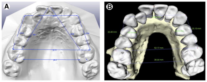
The discrepancy observed at the distolingual cusps on the lower first molars is attributable to the anatomical reconstruction of the occlusal surfaces from the CBCT scan. The models are constructed from a normal CBCT scan when the patient’s teeth are in occlusion. Therefore, there is some overlap of the upper occlusal surfaces with the lower occlusal surfaces. The technicians at Anatomage extrapolate these data with their software to generate the best occlusal surface rendering possible. OrthoCAD uses an impression of the teeth that captures the occlusal surfaces with no interference from any other structures, so the occlusal anatomy is better (Fig 2).
Figure 2.
Linear measurements of a subject’s OrthoCad digital casts (A) and InVivoDental (B).
When visually comparing the models from the 2 imaging modalities, the anterior teeth have more similar anatomy than the posterior teeth. This might be because there is less occlusal overlap in the anterior region than in the posterior region when the teeth are in occlusion. This would depend on the patient and the particular malocclusion present, but the assertion that more occlusal overlap translates to more occlusal anatomy distortion holds when evaluating cone beam generated models. In this study, the most complex occlusal anatomy was on the first molars which are also usually in occlusion during a CBCT scan. Therefore, it is not surprising that any measurement based on these structures would be significantly different from one based on first molars without occlusal distortion. This statistical difference, however, does not represent a clinical significance. All pertinent diagnostic information can be gathered from the models despite the statistical difference present. For example, extraction decisions would probably not be altered because of a small discrepancy that is not discernable clinically by the orthodontist.
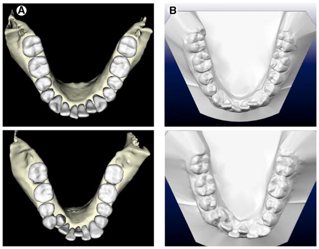
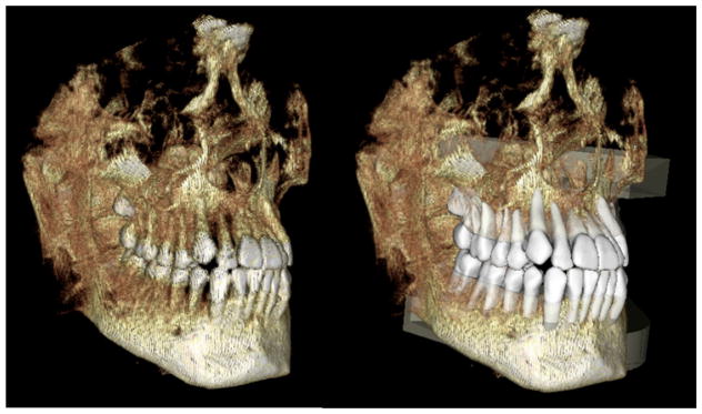
However, not all CBCT generated digital models have the same amount of occlusal distortion. The quality of the scan is very important because Anatomage constructs the models directly from the CBCT data that is present. Limitations within a CBCT machine scan intensity/ dosage settings, the presence of dental restorations, and patient movement can all contribute to model distortion. Higher quality scans allow for the creation of higher quality models. Figure 3 shows OrthoCAD models with their corresponding Anatomage models. The occlusal detail can be variable but in general is adequate for diagnostic information. In addition, the occlusion is also well recorded for buccal segments of the molars and canines (Fig 4).
Figure 3.
Two examples of digital casts and occlusal surface quality from an InVivoDental (A) and OrthoCAD (B) sets.
Figure 4.
The volume rendered CBCT image showing the occlusion and study model with bases superimposed onto CBCT image.
The one limitation in the present study was that the measurements used were linear ones measured between anatomical points rather than of the physical size of the teeth measured in 3 dimensions. A volume comparison in which the OrthoCAD model overlays the CBCT model would be a more accurate comparison of the models in all 3 dimensions. This requires the generation of volume rendered STL file (.stl) from each manufacturer. Unfortunately, this was not available at the time of this study. However, even an STL volume overlay would not be a perfect comparison because it would only be relevant down to the free gingival margin of the teeth. Because OrthoCAD models are generated from an impression, they record the gingiva. Anatomage models are generated from CBCT scans, so they record alveolar bone heights. This is a most important difference to consider if a comparison of the vertical dimension of the models is desired.
Despite the one significantly different measurement found in the present study, the authors consider that cone-beam-generated models from Anatomage are as accurate as OrthoCAD models for the purposes of orthodontic diagnosis. Perhaps the deficiency in occlusal anatomy makes it a poor choice for an indirect bonding set up, but it is considered that the benefits far outweigh this deficiency. The CBCT models offer diagnostic information, such as bone levels, root positions, and temporomandibular joint status that is not present on OrthoCAD models. The elimination of an impression for diagnostic casts is a benefit for both the orthodontist and the patient. If the orthodontist desires an indirect bonding set up, an impression must be taken for that purpose. This would, however, still require an additional impression in an office that employs the OrthoCAD system unless the orthodontist chooses to have OrthoCAD create indirect bonding trays from the original diagnostic impressions sent to them. For the orthodontist who simply wants a digital model for diagnostic purposes and the freedom to fabricate their own indirect bonding set up in their office, Anatomage offers a viable solution.
The idea of gathering all diagnostic records from a single CBCT scan is most intriguing to the orthodontic profession. As computer technology improves, the occlusal distortion in the CBCT models should also improve. Perhaps a thin bite registration device could be placed in the patient’s mouth during the CBCT scan that would record the anatomy of the opposing occlusal surfaces more accurately without opening the bite sufficiently to alter the occlusal relationships. With the constantly improving CBCT technology, the ability to gather all diagnostic records from a single CBCT scan seems imminent.
Conclusions
The following conclusions can be drawn from the present study:
Linear measurements obtained from CBCT image cast indicated a similar level of accuracy when compared with OrthoCAD models.
The accuracy was sufficiently adequate for initial diagnosis and treatment planning in clinical orthodontics.
Further studies need to be carried out to determine the accuracy of the volume of the teeth and the surface of the anatomical crowns for indirect bonding.
References
- 1.Han UK, Vig KWL, Weintraub JA, et al. Consistency of orthodontic treatment decisions relative to diagnostic records. Am J Orthod Dentofac Orthop. 1991;100:212–219. doi: 10.1016/0889-5406(91)70058-5. [DOI] [PubMed] [Google Scholar]
- 2.Garino F, Garino B. From digital casts to digital occlusal set-up: an enhanced diagnostic Tool. World J Orthod. 2003;4:162–166. [Google Scholar]
- 3.Garino B, Garino F. Comparison of dental arch measurements between stone and digital casts. World J Orthod. 2002;3:250–254. [Google Scholar]
- 4.Quimby ML, Vig KW, Rashid RG, et al. The accuracy and reliability of measurements made on computer-based digital models. Angle Orthod. 2004;74:298–303. doi: 10.1043/0003-3219(2004)074<0298:TAAROM>2.0.CO;2. [DOI] [PubMed] [Google Scholar]
- 5.Rheude B, Sadowsky PL, Ferriera A, et al. An Evaluation of the use of digital study models in orthodontic diagnosis and treatment planning. Angle Orthod. 2005;75:300–304. doi: 10.1043/0003-3219(2005)75[300:AEOTUO]2.0.CO;2. [DOI] [PubMed] [Google Scholar]
- 6.Bell A, Ayoub AF, Siebert P. Assessment of the accuracy of a three-dimensional imaging system for archiving dental study models. J Orthod. 2003;30:219–223. doi: 10.1093/ortho/30.3.219. [DOI] [PubMed] [Google Scholar]
- 7.Joffe L. OrthoCAD: digital models for a digital era. J Orthod. 2004;31:344–347. doi: 10.1179/146531204225026679. [DOI] [PubMed] [Google Scholar]
- 8.Mayers M, Firestone AR, Rashid R, et al. Comparison of peer assessment rating (PAR) index scores of plaster and computer-based digital models. Am J Orthod Dentofac Orthop. 2005;128:431–434. doi: 10.1016/j.ajodo.2004.04.035. [DOI] [PubMed] [Google Scholar]
- 9.Mah J. The evolution of digital study models. J Clin Orthod. 2007;41:557–561. [PubMed] [Google Scholar]
- 10.Kau CH, Richmond S. Three-dimensional cone beam computerized tomography in orthodontics. J Orthod. 2005;32:282–293. doi: 10.1179/146531205225021285. [DOI] [PubMed] [Google Scholar]
- 11.Shambarger JH, English JD, Darsey D, et al. Thesis. University of Texas, Dental Branch; Houston: 2007. The Accuracy of OrthoCAD Digital Models Compared to Plaster Models. [Google Scholar]
- 12.Bland JM, Altman DG. Statistical methods for assessing agreement between two methods of clinical measurement. Lancet. 1986;8:307–310. [PubMed] [Google Scholar]


