Abstract
We present a simple 3D event position-estimation method using raw list-mode acquisition and maximum-likelihood estimation in a modular gamma camera with a thick (25mm) monolithic scintillation crystal. This method involves measuring 2D calibration scans with a well-collimated 511 keV source and fitting each point to a simple depth-dependent light distribution model. Preliminary results show that angled collimated beams appear properly reconstructed.
Index Terms: Depth of interaction (DOI), Emission tomography, PET, SPECT, gamma ray, gamma camera, monolithic scintillation crystal, maximum likelihood
I. Introduction
Parallax errors due to uncertainly in depth of interaction (DOI) limit the obtainable resolution in many emission tomography imaging systems. A critical improvement would be the ability to detect the gamma-ray interaction location in all three dimensions. Many different methods for detecting the DOI have been studied. Examples include using an additional detector for depth [1], layers of differing crystal types (phoswich) [2] and using offset segmented crystal arrays [3].
We are interested in DOI estimation in modular gamma cameras with monolithic scintillation crystals [4]. Prior work has shown that analytical forms for the light distribution as a function of depth can be found, and the effect of crystal surface treatments on this function can be described [5]. Recent work treats DOI as a statistical-classification problem for different segmentations in depth [6].
In this work, we demonstrate that 2D calibration data, acquired with a well-collimated beam of gamma rays normal to the face, can be combined with a simple 3D solid-angle model to permit maximum-likelihood (ML) estimation of 3D event-interaction location.
II. Gamma Camera
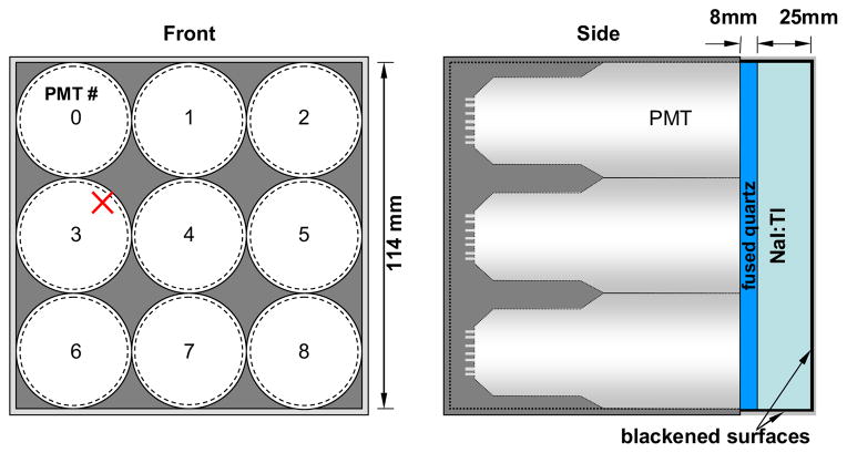
Our gamma camera is composed of thick monolithic NaI:Tl scintillation crystal (114 × 144 × 25 mm) coupled with a 8-mm thick quartz light guide to a 3 × 3 array of photomultiplier tubes (PMT) (Figure 1). Both the crystal face and sides are blackened to increase the depth dependence of the light output.
Fig. 1.
Diagram of modular camera. Note: the red mark is the location used for producing results in later figures (x = 27 mm, y = 45 mm).
III. Acquisition Hardware
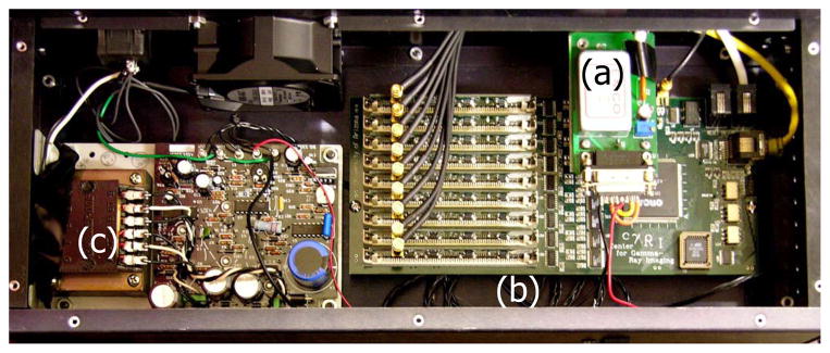
Electronics developed at CGRI were used with the following properties (Figure 2):
Fig. 2.
Picture of acquisition hardware. (a) high voltage supply (b) front-end acquisition electronics. (c) low-voltage supply.
Analog shaping amplifiers with bipolar response
Free-running A/D converters at 33 MHz
Programmable A/D gains for fine control
Pipe-lined event detection in FPGA
List-mode data including all 9 PMT signals
IV. Calibration Process
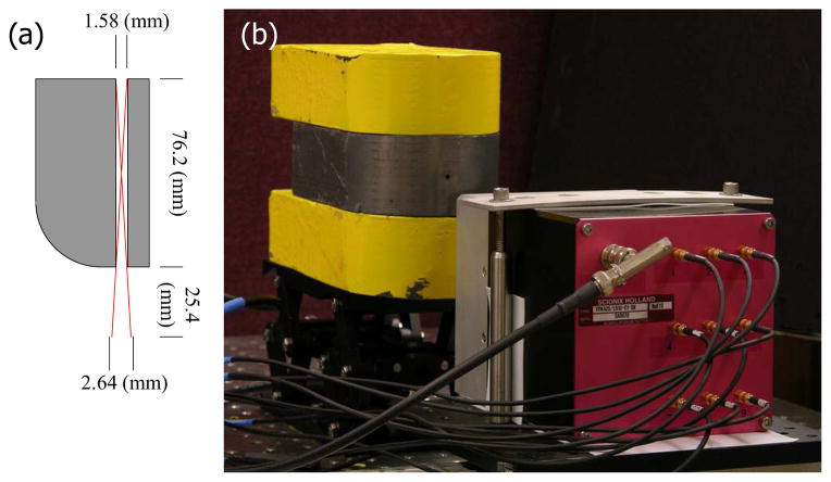
A 152 × 101 × 152 mm (H × W × D) lead collimator with a 1.59 mm bore diameter and a 76.2 mm bore length was used to produce a finely collimated beam from a syringe of fluorine-18. This collimated source was scanned in a plane parallel to the front surface of the camera on a 3 × 3 mm 2D grid while list-mode event data were collected (Figure 3). Each list-mode data packet contains the peak amplitude for all nine PMTs of the pulse resulting from a single event. This lead collimator was also used to acquire event data for beams incident at various angles to the camera face.
Fig. 3.
(a) A diagram of the collimator and geometrically constrained beam spread. (b) A picture of camera calibration in progress.
V. Maximum Likelihood Position Estimation
Since we collect list-mode data with all nine PMT signals for each event, we can estimate the 3D interaction position and energy of that event using maximum likelihood estimation [7]. We assume that the energy of the interaction is known and that the statistics that describe the number of primary photoelectrons (Ni) generated by a given PMT i from a scintillation event at a given location are Poisson:
Because the distribution is Poisson, it can be characterized fully by its mean ( ) which we will refer to as the mean detector response function (MDRF). Since we measure voltages, Ni is approximated by the rounded result of the voltage output of PMT i divided by the gain of that PMT (Ni = Round [Vi/Gi]).
Because we cannot restrict scintillation events to a given 3D interaction location, we cannot measure the 3D MDRF directly. By describing the acquired 2D calibration data at each point and for each PMT as the marginalization of the distribution in depth (z), we obtain:
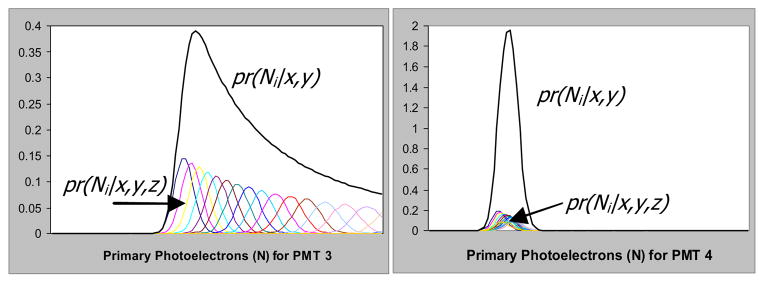
where L is the thickness of the crystal and pr (z) is the probability density function for a gamma-ray interaction at depth z. Assuming that this probability function in depth follows Beer’s law of absorption, we can estimate the 3D MDRF by modeling the forward problem and comparing it to the 2D calibration data. Figure 4 shows both pr (Ni | x, y, z) weighted by the prior and the resultant pr (Ni | x, y) calculated from a summation of the conditional probabilities.
Fig. 4.
Two example reconstructions of pr(Ni|x,y) from pr(Ni|x,y,z) calculated from a possible 3D MDRF for the location indicated in Fig 1.
VI. A Simplified Approach to the 3D MDRF
This simple approach proposes that the largest factor determining the depth dependence of the MDRF for a given PMT is the variation in the solid angle subtended by that PMT as other light paths are suppressed by the blackened surface treatments of the crystal [7].
In this model, we describe the 3D MDRF for a given PMT i as the product of a 2D light response function (LRFi) for each PMT and a normalized solid-angle function:
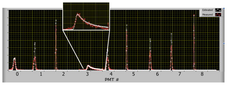
Here Ωi is the solid angle for PMT i for an event at location x, y, z and can be determined analytically. The LRF is found using a non-linear least squares algorithm to fit the marginalized distribution from the 3D MDRF to the measured distribution for a single point. Results of this fitting process for a single x, y location are shown in Figure 5. The MDRF in depth for all nine PMTs is shown in Figure 6.
Fig. 5.
Results from the fitting process for the location indicated in Fig. 1. The measured distributions are shown in red for all 9 PMTs concatenated together, and the white line is the marginalized distribution as generated from the 3D MDRF.
Fig. 6.
Plots of the MDRF in depth at the location indicated in Fig. 1 for all nine PMTs. (a) shows PMT 3; (b) all other PMT signals.
VII. 3D Position Estimation Results
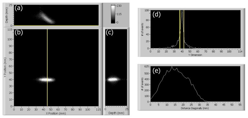
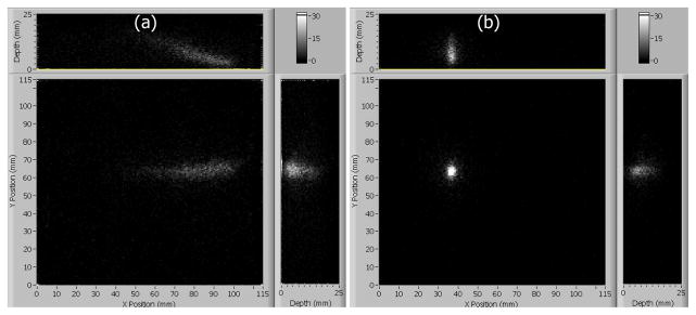
Multiple acquisitions were taken with collimated beams oriented at different angles relative to the camera face. For each event, a 3D position was found using a maximum-likelihood contracting-grid search algorithm described elsewhere [8]. Example results with the beam oriented at 45° are shown in Figure 7. Three projection views of the events in the crystal are shown from the (a) top side, (b) entrance face, and (c) right side of the crystal. Likelihood thresholding was also applied to reject scattered events, accepting 50% of the events [9]. Other slices are shown in (d) and (e). Figure 8 shows results from beams at both 65° (a) and 0° (b).
Fig. 7.
Results from position estimation of 50,000 events collected with collimator oriented at 45° from the camera face. (a)–(c) Projections from the top, front, and right of the crystal. (d) A plot of the cut along the yellow line in (b) with the FWHM shown as 3.4 mm. (e) A 45° cut through plot (a) showing the falloff in depth.
Fig. 8.
(a) Position estimation on 7,000 events collected with collimator oriented at 65° from the normal to the camera face (b) and on 2,500 events collected with collimator oriented normal to the camera face.
VIII. Discussion
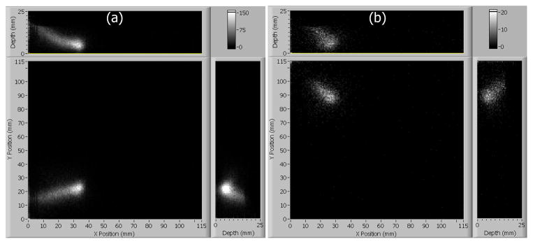
The slant-beam reconstructions show that, while the simplified model works well toward the center of the crystal, problems arise towards the corners where the majority of the signal is in only 4 of the 9 PMTs. Figure 9 shows that, in the corners, both normal and angled beams tend to be distorted towards the entrance face and corner of the crystal. This suggests a systematic error in this simplified MDRF.
Fig. 9.
(a) Position estimation on 50,000 events collected with collimator oriented at 45° (b) and 2,500 events oriented normal to the camera face both show similarly that deeper portions of the beams are forced towards the face and corner of the crystal.
To quantify the resolution of the camera, the Cramer-Rao lower bound on the variance of the 3D position estimate was calculated using our 3D MDRFs [7]. Figure 10 shows a section through the crystal perpendicular to the x-axis with the geometric mean of the lateral resolution (a) and the depth resolution (b). In most of the crystal the FWHM of the point spread function is below 3.5 mm laterally and 2 mm in depth.
Fig. 10.
Resolution estimates as calculated from the Cramer-Rao bounds computed from the 3D MDRFs for a section perpendicular to the x-axis in the center of the crystal. (a) Geometric average of lateral resolution (FWHM). (b) Depth resolution (FWHM).
IX. Conclusions
Our results suggest that 3D event-position estimation is possible with detectors on only one side of a monolithic crystal. An increase in the total light collected by the PMTs will yield improvements in the position estimation. Future work will consider scintillation crystals with more light output and retroreflectors on the surface opposite the PMTs as well as higher-density photodetectors (multi-anode PMTs). Other improvements might include more complicated MDRF models that extend the solid angle approximation for depth. A companion paper reports a simulated proof-of-concept for the calibration of 3D MDRF parameters by maximizing the likelihood of the list-mode data [10].
Acknowledgments
This work was supported in part by the U.S. National Institutes of Health NIBIB under Grant P41-EB002035.
References
- 1.Moses WW, Derenzo SE. Design studies for a PET detector module using a PIN photodiode to measure depth of interaction. IEEE Trans Nucl Sci. 1994 Aug;41(4):1441–1445. [Google Scholar]
- 2.Seidel J, Vaquero JJ, Siegel S, Gandler W, Green MV. Depth identification accuracy of a three-layer phoswich PET detector module. IEEE Trans Nucl Sci. 1999 Jun;46(3):485–490. [Google Scholar]
- 3.Liu H, Omura T, Watanabe M, Yamashita T. Development of a depth of interaction detector for gamma-rays. Nucl Instr Meth. 2001;A459:182–190. [Google Scholar]
- 4.Furenlid LR, Wilson DW, Chen Y, Kim H, Pietraski PJ, Crawford MJ, Barrett HH. FastSPECT II: A second-generation high-resolution dynamic SPECT imager. IEEE Trans Nucl Sci. 2004 Jun;51(3):631–635. doi: 10.1109/TNS.2004.830975. [DOI] [PMC free article] [PubMed] [Google Scholar]
- 5.Tomitani T, Futami Y, Izeki Y, Kouda S, Nishio T, Murakami T, Kitagawa A, Kanazawa M, Urakabe E, Shinbo M, Kanai T. Depth encoding of point-of-interaction in thick scintillation cameras. Nuclear Science Symposium, Conference Record. 1999;3:1182–1186. [Google Scholar]
- 6.Ling T, Lewellen TK, Miyaoka RS. Depth of interaction decoding of a continuous crystal detector module. Phys Med Biol. 2007;52:2213–2228. doi: 10.1088/0031-9155/52/8/012. [DOI] [PubMed] [Google Scholar]
- 7.Barrett HH, Myers KJ. Foundations of image science. John Wiley and Sons; Hoboken: 2004. [Google Scholar]
- 8.Furenlid LR, Hesterman JY, Barrett HH. Real-time data acquisition and maximum-likelihood estimation for gamma cameras. Real Time Conference, 2005. 14th IEEE-NPSS; June 2005; p. 4. [DOI] [PMC free article] [PubMed] [Google Scholar]
- 9.Kupinski MA, Barrett HH, editors. Small-animal SPECT imaging. Springer; 2005. p. 75. [Google Scholar]
- 10.Hunter WCJ, Moore SK, Furenlid LR, Barrett HH. Method of calibrating response statistics for ML estimation of 3D interaction position in a thick-detector gamma camera. Nuclear Science Symposium, Conference Record. 2007 doi: 10.1109/NSSMIC.2007.4437079. submitted for publication. [DOI] [PMC free article] [PubMed] [Google Scholar]
- 11.Olivier P, Therrien M, Pouliot N, Laperriere L, Gagnon D. Efficient computation of the solid angle function and its derivatives. NSS-MIC IEEE Conference Record. 1992 Oct;2:1246–1248. [Google Scholar]


