Abstract
Harmonic Motion Imaging for Focused Ultrasound (HMIFU) is a technique that can perform and monitor high-intensity focused ultrasound (HIFU) ablation. An oscillatory motion is generated at the focus of a 93-element and 4.5 MHz center frequency HIFU transducer by applying a 25 Hz amplitude-modulated signal using a function generator. A 64-element and 2.5 MHz imaging transducer with 68kPa peak pressure is confocally placed at the center of the HIFU transducer to acquire the radio-frequency (RF) channel data. In this protocol, real-time monitoring of thermal ablation using HIFU with an acoustic power of 7 W on canine livers in vitro is described. HIFU treatment is applied on the tissue during 2 min and the ablated region is imaged in real-time using diverging or plane wave imaging up to 1,000 frames/second. The matrix of RF channel data is multiplied by a sparse matrix for image reconstruction. The reconstructed field of view is of 90° for diverging wave and 20 mm for plane wave imaging and the data are sampled at 80 MHz. The reconstruction is performed on a Graphical Processing Unit (GPU) in order to image in real-time at a 4.5 display frame rate. 1-D normalized cross-correlation of the reconstructed RF data is used to estimate axial displacements in the focal region. The magnitude of the peak-to-peak displacement at the focal depth decreases during the thermal ablation which denotes stiffening of the tissue due to the formation of a lesion. The displacement signal-to-noise ratio (SNRd) at the focal area for plane wave was 1.4 times higher than for diverging wave showing that plane wave imaging appears to produce better displacement maps quality for HMIFU than diverging wave imaging.
Keywords: Bioengineering, Issue 105, HIFU ablation, Harmonic motion imaging, Real-time monitoring, High frame rate imaging, Elastography, Lesion monitoring, Liver ablation, Canine liver
Introduction
High Intensity Focused Ultrasound (HIFU) is a technique that generates temperature elevation at the focal region and can be used to ablate cancerous tissue 1. Temperature elevation at the focus causes thermal lesions in the tissue 2. In order to avoid overtreating a region and to reduce treatment duration, it is imperative to reliably monitor the ablation. Magnetic resonance-guided focused ultrasound (MRgFUS) is the main technique used in clinic to guide and monitor HIFU treatment 3. MRI provides high spatial resolution images of the treated region with tissue displacement or thermal dose but has a frame rate of 0.1-1 Hz and is costly. Several ultrasound-based techniques such as B-mode imaging 4, passive acoustic mapping 5, shear wave imaging 6 and acoustic radiation force impulse 7 have been developed to guide and monitor thermal ablation. However, B-mode imaging and passive acoustic mapping do not provide imaging of mechanical properties of the ablated region which is useful to the operator to improve lesion delivery.
Shear wave imaging and acoustic radiation force impulse can both characterize the elasticity of the tissue by measuring acoustic radiation force-induced displacements 7,8. However, in both methods, the HIFU treatment is typically interrupted to monitor the ablation. Our group has developed a technique called Harmonic Motion Imaging for Focus Ultrasound (HMIFU) which can monitor the HIFU treatment with ultrasound without stopping the ablation9,10. Briefly, a HIFU transducer sends an amplitude-modulated wave to the region to ablate while simultaneously generating an oscillatory motion in the focal region. A co-axially aligned ultrasound transducer is used to image this oscillation. The magnitude of the induced motion is related to the stiffness of the tissue.
To ensure proper lesion delivery, the temporal resolution of real-time monitoring is of key interest in ablation guidance. Recently, our group has shown real-time streaming of displacement at a frame rate up to 15 Hz, imaged with diverging waves in a narrow field of view and using a fast image reconstruction method 11. Several beamforming techniques can be used to image the displacements. A large field of view can be obtained with diverging wave imaging by changing the delay profile but the axial direction is not aligned with the HIFU beam on the lateral regions and the wave is attenuated due to geometric spreading in the lateral direction, which can affect the quality of the displacement estimation. In contrast, the lateral field of view for plane wave is upper bounded by the active aperture but the axial direction is aligned with the HIFU beam at the focus and there is no geometric spreading in the lateral direction. Depending on the type of application, one or the other imaging method can be selected. The objectives of this protocol are to show how plane wave imaging can provide real-time streaming of displacements images using HMIFU during ablation and to compare the quality of the motion estimation between diverging and plane wave imaging.
Protocol
This protocol was approved by the Institutional Animal Care and Use Committee of Columbia University. All the data acquisition and processing were performed using the Matlab environment.
1. Experimental Set-up
Degas an ex vivo canine liver sample during 90 min. Put the liver sample in a tank filled with degassed Phosphate Buffered Solution (Figure 1). Fix the liver sample on an acoustic absorber with needles at the extremities of the liver.
- Insert a 64-element, 0.32 mm pitch, 2.5 MHz center frequency phased array (imaging) through a circular hole located in the center of a 93-element hemispherical array HIFU transducer (therapeutic) at 4.5 MHz center frequency, 70 mm focal depth and 1.7 mm x 0.4 mm focal size11. Align both transducers co-axially and fix the imaging transducer into the therapeutic transducer with adjustment screws.
- Cover the HIFU transducer with a volume-controlled polyurethane membrane filled with flowing degassed water to cool it down. Mount the transducer assembly on a computer-controlled 3-D positioner.
Connect the HIFU transducer to a function generator sending a 25 Hz amplitude modulated sine waveform with 500 mV maximum amplitude. Connect the imaging transducer to a fully programmable ultrasound system using the software Matlab. Note: A software associated with the ultrasound system and using the Matlab environment has to be installed on the computer connected to the system. A 50 dB RF amplifier and a matching network should be placed between the HIFU transducer and the function generator to respectively amplify the power and match the impedance.
- Create a polar grid, using Matlab, starting 50 mm from the surface of the array and 40 mm deep in the radial direction with a spatial step of 9.625 µm and of 90° in the azimuthal direction with 128 lines and which origin is the focus of the diverging wave. Define the source of the diverging wave 10.24 mm (half the size of the aperture) behind the surface of the array and centered in the lateral direction.
- Create a Cartesian grid, using Matlab, starting 50 mm from the surface of the array and 40 mm deep in the axial direction with a spatial step of 9.625 µm and 20 mm wide in the lateral direction with 64 lines for the plane wave. Define the source of the plane wave on the surface of the array. For each grid, compute the time from the source to each point of the grid and back to each element of the array.
- Enter “ReconMat_DW” for diverging wave imaging or “ReconMat_PW” for plane wave imaging in the Matlab command window and press “Enter” to create a reconstruction matrix associated with a standard delay-and-sum algorithm for each grid. Apply the delay-and-sum algorithm to each vector of the standard basis and retrieve the non-zeros elements of the resulting matrix11. Allocate the non-zero elements obtained from the resulting matrix to the sparse matrix at the corresponding location. Save the reconstruction matrix on the computer hard drive. Note: The diverging and the plane wave methods use two distinct reconstruction matrices.
- Cast the reconstruction matrix to a GPU matrix. Enter “SetUpP4_2Flash_4B_streaming_DW” for diverging wave imaging or “SetUpP4_2Flash_4B_streaming_PW” for plane wave imaging in the Matlab command window and press “Enter” to create a setup file for the ultrasound channel data acquisition using the script associated with the phased array and provided by the manufacturer of the ultrasound system. Name the setup file “P4-2Flash_DivergingWave.mat” for diverging wave imaging and “P4-2Flash_PlaneWave.mat” for plane wave imaging. Note: A commercial software package has to be installed on the computer to cast the reconstruction sparse matrix to a GPU matrix.
Synchronize the ultrasound system with the function generator using an external trigger so that high frame rate ultrasound data acquisition of the liver starts at the same time as HIFU.
Open Matlab. Run the setup script “SetUpP4_2Flash_4B.m” provided by the ultrasound system manufacturer to use B-mode imaging. Name the created setup file: “P4-2Flash_4B_Bmode.mat”. Use the “VSX” command and when “Name of .mat file to process:” is prompted, enter the name of the setup file “P4-2Flash_4B_Bmode.mat”. Move both transducers and use the B-mode display that appeared on the computer screen to position them in the targeted region of the liver to ablate. Target a region approximately 1 cm under the surface of the liver to avoid high ultrasound attenuation due to absorption. Save a conventional B-mode image of the liver on the computer. Note: Here we performed HIFU ablations at 11 different locations in two liver specimens by moving the transducers with the 3-D positioner for each ablation.
2. Ultrasound Data Acquisition
Open Matlab. Use the “VSX” command and when “Name of .mat file to process:” is prompted, enter the name of the setup file “P4-2Flash_DivergingWave.mat” for diverging wave imaging or “P4-2Flash_PlaneWave.mat” for plane wave imaging. Start the HIFU and apply it during 2min to the targeted region.
Acquire the RF channel data at 1,000 frames per second during 2 min using diverging waves. Alternatively, acquire the RF channel data at 1,000 frames per second during 2 min using plane waves.
Transfer the data to a host computer every 200 frames via a PCI express cable. Alternatively, for real-time streaming, acquire the RF channel data at 167 frames per second during 2 min using plane waves and transfer the data to a host computer every 2 frames. Note: The imaging methods with set of 200 frames provides high temporal resolution within each set but create gaps between each set and is appropriate for off-line processing. The imaging method at 167 fps has a lower temporal resolution but does not create any gaps across the entire ablation time and is appropriate for real-time streaming.
Cast the RF channel data matrix to a single precision GPU matrix with Matlab. Multiply the RF channel data matrix by the reconstruction matrix to obtain the reconstructed RF data11.
3. Displacement Imaging
Create a 6th order Butterworth low pass filter at 4 MHz cutoff frequency using the DSP System Toolbox of Matlab. Apply this low pass filter to the reconstructed RF data to filter out the 4.5 MHz HIFU component.
Estimate the axial displacement between consecutive frames using 1-D normalized cross-correlation with a 3.1mm-window length and 90% overlap.
Create a 6th order Butterworth low pass filter at 100 Hz cutoff frequency using the DSP System Toolbox of Matlab. Apply this low pass filter to the temporal displacement data using Matlab to retrieve the 50 Hz-oscillatory frequency component.
Define a region of interest (ROI) as the focal region at -6 dB (1.7 x 0.4 mm in water) and located 70 mm away from the transducer surface. Extract the displacement data in this ROI. Estimate the displacement signal-to-noise ratio (SNRd) at the focal region after 2 min of ablation as the ratio between the mean displacement and the standard deviation of the displacement in the ROI.
Extract the 50 Hz temporal displacement signal at the focus from the displacement matrix data. Convert the temporal displacement signal at the focus into audible sound using Matlab.
Representative Results
Real-time streaming of HMI displacement during HIFU ablation can be obtained using diverging and plane wave imaging. Figure 2 is a video screen capture showing real-time display of acoustic radiation force induced displacement using plane wave imaging in in vitro canine livers during HIFU ablation. The displacements are streamed in real-time on the computer screen at a display frame rate of 4.5 Hz. Positive displacements are shown in red and negative displacements in blue. Lesions were successfully delivered using HIFU ablation. Figure 3 shows the lesion obtained in the liver after the ablation corresponding to Figure 2.
Decrease of HMI peak negative displacement amplitude during HIFU ablation can be imaged with both diverging and plane wave imaging. Figure 4 shows HMI peak negative displacement at different stage of the ablation with diverging and plane wave imaging. Peak negative displacements were shown both without and with overlay on the B-mode to see more clearly the displacement pattern and to see the targeted region in the liver respectively. The 50 Hz HMI displacement sound corresponding to the ablation monitored with plane wave (Figure 4C) was incorporated to the video. The decrease of HMI displacement amplitude due to the ablation can be heard which provides an additional monitoring tool. Figure 4 also indicates that the size of the region excited by HIFU increases during the ablation. Figure 5A and 5B shows the HMI displacements at the focal region during the ablation for diverging and plane wave respectively. The decrease in HMI displacement magnitude is clearly visible both for diverging and plane wave imaging. Figure 6 shows the peak-to-peak displacement decrease for all the targeted locations in the liver both for diverging (Figure 6A) and plane (Figure 6B) wave imaging. The peak-to-peak displacement decrease for plane wave is not significantly different for the one obtained for diverging wave.
Plane wave imaging was found to have a higher SNRd at the focus than diverging wave imaging. Figure 7 shows the SNRd in the ROI for all the lesion positions in the liver for diverging (Figure 7A) and plane (Figure 7B) wave imaging. The averaged SNRd for plane was 1.7 times higher than for diverging wave imaging.
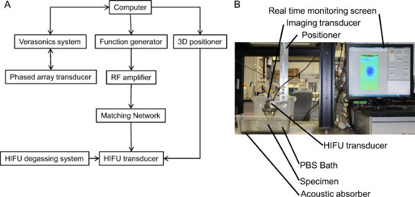 Figure 1. Experimental set-up. (A) Representation of the HMIFU system. (B) Picture of the experimental set-up. Please click here to view a larger version of this figure.
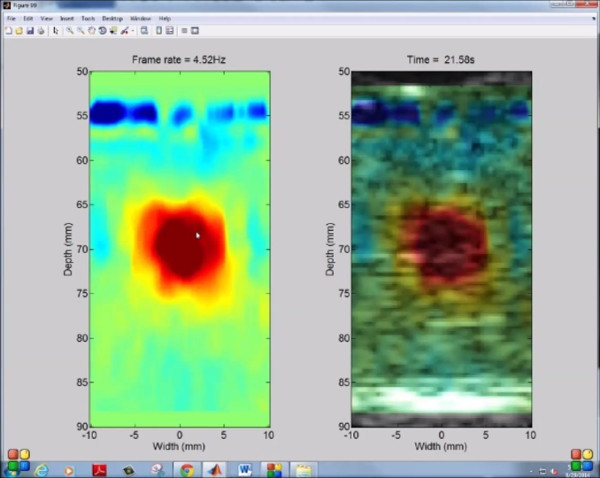 Figure 2. Real-time HMI displacements. Capture screen of the computer showing real-time streaming of HMI displacements with plane wave imaging during HIFU ablation of a canine liver at 4.5Hz display frame rate. The left hand side panel shows the filtered HMI displacements and the right hand side panel shows the filtered HMI displacements overlaid on the pre-ablation B-mode of the liver. Please click here to view a larger version of this figure.
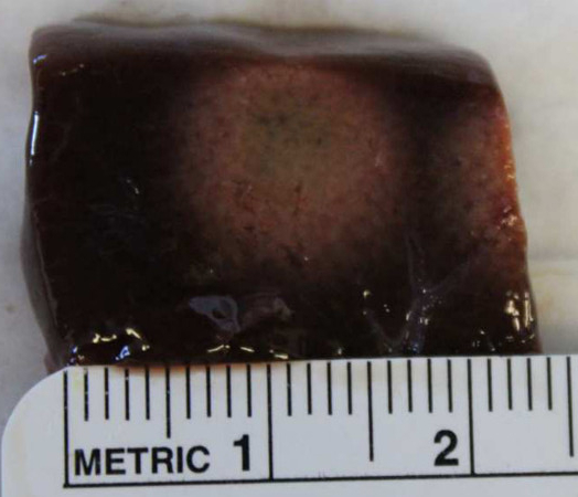 Figure 3. Lesion induced by HIFU. Picture of the middle cross-section of a lesion following HIFU treatment. Please click here to view a larger version of this figure.
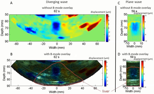 Figure 4. Diverging and plane wave imaging of the displacements. Peak negative HMI displacement imaging during HIFU ablation of a canine liver using diverging wave with no B-mode overlay (A), with B-mode overlay (B), using plane wave imaging with no B-mode overlay (C) and with B-mode overlay (D). The 50 Hz HMI displacement sound corresponding to the ablation monitored with plane wave (Figure 4C) was incorporated to the video. Please click here to view a larger version of this figure.
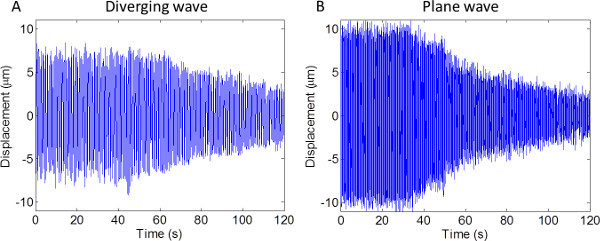 Figure 5. HMI focal displacement. HMI displacement at the focal region during HIFU ablation using diverging (A) and plane (B) wave imaging. Please click here to view a larger version of this figure.
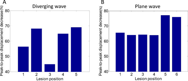 Figure 6. Peak-to-peak displacement decrease. Peak-to-peak displacement decrease at the focal region during HIFU ablation using diverging (A) and plane (B) wave imaging. Please click here to view a larger version of this figure.
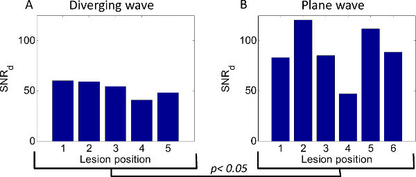 Figure 7. Displacement signal-to-noise ratio. The displacement signal-to-noise ratio at the focus for diverging (A) and plane (B) wave imaging for different ablation position. Please click here to view a larger version of this figure.
Discussion
Real-time monitoring of HIFU lesions is important to ensure proper and efficient lesion delivery. As the lesion forms, the tissue stiffens and its motion amplitude under excitation decreases. Applying HIFU in a region of the tissue results in an acoustic radiation force that induces tissue displacement. The relative change in displacement is a surrogate of relative change in tissue stiffness. This technique offers the advantage of monitoring HIFU lesion without stopping the treatment in contrast to other ultrasound based methods. The temporal resolution of the real-time monitoring in this study (4.5 Hz) was higher than that obtained in MR-guided HIFU ablation (1 Hz).
Fast processing of ultrasound RF data is a critical step for real-time streaming of displacement. The reconstruction of the image is the slowest step of the processing. In this protocol, the speed of the image reconstruction was optimized by obtaining the entire frame using a single operation. This operation consists in multiplying the RF channel data by a matrix. Only the non-zero elements of the matrix were allocated to optimize computation time and the
multiplication was performed on a GPU. A fast 1-D normalized cross-correlation method was used to estimate the displacements. A window overlap of 80% allows a good trade-off between the computation time and the axial resolution of the displacement images.
The transmit beamforming method can also affect the quality of the displacement image. The SNRd was found to be significantly lower for diverging than for plane wave imaging using a two-sample t-test. The magnitude of the displacement was also lower for diverging than for plane wave imaging. This could be explained by the fact that the axial direction of the diverging wave is not aligned with the HIFU beam in the entire ROI due to the divergent nature of the wave in contrast to the plane wave. The lower peak-to-peak displacement decrease found for lesion #3 for diverging wave imaging can be due the presence of a vessel at the center of the lesion observed after gross pathology. The lower SNRd found for lesion #4 for plane wave imaging can be due to the proximity of the focus to the surface of the liver. It also has to be noted that attenuation due to geometric spreading in the lateral direction occurs for diverging waves and not for plane wave which can affect the quality of the motion estimation. However, when using the same ultrasound transducer, the diverging wave imaging offers a larger field of view than plane wave imaging which is of interest to continuously image the largest part of the region to ablate.
In this protocol, a phased array was utilized to image the displacements so that only a cross-section of the ablated region was imaged. A 2-D array transducer could be used to image the entire volume of the ablated region. The ablation at different locations of the liver was achieved by moving the transducer relative to the liver. Beam steering could be performed with the HIFU probe to target different locations of the region to be treated to allow for more proper targeting. Besides the aforementioned technical improvements, future directions include the clinical translation of this method.
Disclosures
The authors declare that they have no competing financial interests.
Acknowledgments
This work was supported by the National Institutes of Health (R01-EB014496). The authors would like to thank Iason Apostolakis for his contribution to the experiments.
References
- Al-Bataineh O, Jenne J, Huber P. Clinical and future applications of high intensity focused ultrasound in cancer. Cancer Treat Rev. 2012;38:346–353. doi: 10.1016/j.ctrv.2011.08.004. [DOI] [PubMed] [Google Scholar]
- Dewhirst MW, Viglianti BL, Lora-Michiels M, Hanson M, Hoopes PJ. Basic principles of thermal dosimetry and thermal thresholds for tissue damage from hyperthermia. Int J Hyperthermia. 2003;19:267–294. doi: 10.1080/0265673031000119006. [DOI] [PubMed] [Google Scholar]
- Napoli A, et al. MR-guided high-intensity focused ultrasound: current status of an emerging technology. Cardiovasc Intervent Radiol. 2013;36:1190–1203. doi: 10.1007/s00270-013-0592-4. [DOI] [PubMed] [Google Scholar]
- Gudur MS, Kumon RE, Zhou Y, Deng CX. High-frequency rapid B-mode ultrasound imaging for real-time monitoring of lesion formation and gas body activity during high-intensity focused ultrasound ablation. IEEE Trans Ultrason Ferroelectr Freq Control. 2012;59:1687–1699. doi: 10.1109/TUFFC.2012.2374. [DOI] [PubMed] [Google Scholar]
- Jensen CR, Cleveland RO, Coussios CC. Real-time temperature estimation and monitoring of HIFU ablation through a combined modeling and passive acoustic mapping approach. Phys Med Biol. 2013;58:5833–5850. doi: 10.1088/0031-9155/58/17/5833. [DOI] [PubMed] [Google Scholar]
- Mariani A, et al. Real time shear waves elastography monitoring of thermal ablation: in vivo evaluation in pig livers. J Surg Res. 2014;188:37–43. doi: 10.1016/j.jss.2013.12.024. [DOI] [PubMed] [Google Scholar]
- Bing KF, Rouze NC, Palmeri ML, Rotemberg VM, Nightingale KR. Combined ultrasonic thermal ablation with interleaved ARFI image monitoring using a single diagnostic curvilinear array: a feasibility study. Ultrason Imaging. 2011;33:217–232. doi: 10.1177/016173461103300402. [DOI] [PMC free article] [PubMed] [Google Scholar]
- Athanasiou A, et al. Breast lesions: quantitative elastography with supersonic shear imaging--preliminary results., Radiology. 2010;256:297–303. doi: 10.1148/radiol.10090385. [DOI] [PubMed] [Google Scholar]
- Maleke C, Konofagou EE. Harmonic motion imaging for focused ultrasound (HMIFU): a fully integrated technique for sonication and monitoring of thermal ablation in tissues. Phys Med Biol. 2008;53:1773–1793. doi: 10.1088/0031-9155/53/6/018. [DOI] [PubMed] [Google Scholar]
- Maleke C, Konofagou EE. In vivo feasibility of real-time monitoring of focused ultrasound surgery (FUS) using harmonic motion imaging (HMI) IEEE Trans Biomed Eng. 2010;57:7–11. doi: 10.1109/TBME.2009.2027423. [DOI] [PubMed] [Google Scholar]
- Hou GY, et al. Sparse matrix beamforming and image reconstruction for 2-D HIFU monitoring using harmonic motion imaging for focused ultrasound (HMIFU) with in vitro validation. IEEE Trans Med Imaging. 2014;33:2107–2117. doi: 10.1109/TMI.2014.2332184. [DOI] [PMC free article] [PubMed] [Google Scholar]


