

Na-O layer provides Na+ diffusion pathway and storage site, whereas benzene layer provides e−conduction pathway and redox center.
Keywords: Carbonyl materials, Organic electrode, Organic-inorganic layered structure, Storage mechanism, Na+ ion transport, Sodium-ion batteries, energy storage
Abstract
Organic carbonyl compounds represent a promising class of electrode materials for secondary batteries; however, the storage mechanism still remains unclear. We take Na2C6H2O4 as an example to unravel the mechanism. It consists of alternating Na-O octahedral inorganic layer and π-stacked benzene organic layer in spatial separation, delivering a high reversible capacity and first coulombic efficiency. The experiment and calculation results reveal that the Na-O inorganic layer provides both Na+ ion transport pathway and storage site, whereas the benzene organic layer provides electron transport pathway and redox center. Our contribution provides a brand-new insight in understanding the storage mechanism in inorganic-organic layered host and opens up a new exciting direction for designing new materials for secondary batteries.
INTRODUCTION
With the rapid development of renewable wind and solar energy sources, a large-scale electrical energy storage system is called for smooth integration of these intermittent energies into the grid (1, 2). Electrochemical energy storage technology is one of the most promising means to store the electricity in large scale because of its flexibility, high-energy conversion efficiency, and simple maintenance (1–3). Rechargeable batteries with high efficiency, low cost, long cycle life, and high safety are desired. Among them, room temperature sodium-ion batteries with abundant resources have shown great promise for such applications (4–7). However, the lack of negative electrodes with appropriate storage voltage impedes the development of highly efficient, long-lasting, and highly safe sodium-ion batteries. The low sodium storage voltage of carbon-based materials (8–10) and Ti-based oxides (3, 11–13) will lead to the formation of a solid-state electrolyte interface (SEI) layer owing to the electrolyte reduction below 0.8 V versus Na+/Na, resulting in low coulombic efficiency (table S1). Polyanionic NaTi2(PO4)3 displays a high operating voltage of 2.1 V versus Na+/Na via Ti4+/Ti3+ conversion with high coulombic efficiency of >95%, which is too positive for high energy density and can only be considered with aqueous electrolytes (14). Therefore, it is essential to explore the negative electrode materials with storage voltage between 1.0 and 1.5 V to avoid the formation of SEI and improve first coulombic efficiency.
Organic electrode materials can be easily made from biomass or recyclable resources without expensive transition metal elements; therefore, the cost of organic-based rechargeable batteries can be significantly reduced (15–26). In a conjugated carbonyl compounds, the storage mechanism was simply described as the reversible redox of carbon-oxygen double bond in a conjugated system (16). The bond energy of C=O is strongly affected by its chemical environment. For most carbonyl compounds with quinone-type redox center, the average lithium storage voltage is about 2.2 V versus Li+/Li (15, 16, 20), whereas conjugated carboxylates with carboxyl redox center, including aromatic carboxylates and chain conjugated carboxylates, have lithium storage voltage below 1.0 V versus Li+/Li. Moreover, inductive and resonance effects of substituent result in the change on electron density of conjugated carbon scaffolding, causing a higher/lower redox potential than the nonsubstituted compound (19, 26). Disodium terephthalate (Na2C8H4O4) with two carboxyl groups was the first reported organic negative electrode for sodium-ion batteries (27). It exhibits a high reversible capacity of 250 mAh g−1 at a storage voltage of 0.29 V versus Na+/Na but with very low coulombic efficiency. So far, the research on carbonyl compound is mainly focusing on the search for new materials and the improvement of their electrochemical performance. The structure characteristic and reaction mechanism of carbonyl compounds are still not clear. Here, we discover a new structure model of Na storage host with inorganic and organic repeat units in a layered framework. The inorganic layer functions as a Na+ ion transport pathway and storage site, whereas the organic layer serves as electron conduction and storage. We take the sodium salt of 2,5-dihydroxy-1,4-benzoquinone (2,5-DBQ) (Na2C6H2O4) with Na-O octahedral layer and π-stacked benzene organic layer as an example to elucidate Na storage mechanism.
RESULTS
This inorganic-organic layered material Na2C6H2O4 was prepared by a simple liquid-phase reaction using precursors of 2,5-DBQ and NaOH at room temperature. After salt formation, the thermostability is significantly improved, as shown in fig. S1. The morphology of the resulting samples was investigated with scanning electron microscopy (SEM). As shown in fig. S2, the particle size of the sample prepared from the liquid-phase reaction is about 50 nm.
The crystal structure of this compound was resolved in an ab initio manner from powder diffraction data. To solve this problem, we used 2,5-DBQ dianion and sodium cation as independent motifs in a simulated annealing approach; an initial structure is obtained, then corrected by density functional theory (DFT) geometry optimization, and finally refined via the Rietveld method. As shown in Fig. 1A, the final structure obtained after refinement produced an excellent fit to the diffraction pattern, with Rp = 2.75% and Rwp = 3.70%. The compound crystallizes in a centrosymmetric triclinic system (space group P–1), with lattice constants of a = 3.5229(2) Å, b = 6.0240(3) Å, c = 7.3975(4) Å, α = 74.269(2), β = 81.823(2), γ = 93.870(2), and V = 148.6 Å3. The detailed crystallographic information is listed in table S2. Figure 1B displays a typical layered structure of Na2C6H2O4, where an Na-O inorganic layer and parallel-orientated benzene organic layer are alternately arranged along the c direction. For each 2,5-DBQ molecule, all of four carbonyl groups with very similar bond lengths of 1.2792 and 1.2769 Å are extended outward from the benzene ring layer and coordinated to sodium atoms, whereas the two C–H bonds are left inside the layer. This similar bond length of all C–O bonds gives a new insight in understanding the structure, which cannot be described as discrete C=O and C–O bonds (hereafter “carbonyl”), but all belong to the same conjugation. Each sodium atom is coordinated with six oxygen atoms (two from the same 2,5-DBQ molecule and the remaining four are from different 2,5-DBQ molecules) with the Na-O distance range from 2.3433 to 2.5543 Å to form the Na-O octahedron. The inorganic layer consists of Na-O octahedrons connected through edge sharing. Moreover, each carbonyl is coordinated with three different sodium atoms above and below the benzene ring plane. The sodium atoms are arranged in S line along the a axis, forming a possible one-dimensional (1D) Na+ ion transport pathway as corroborated later. The parallel-stacked benzene rings through π interaction are along the a axis, and the distance between neighboring benzene rings is 3.157 Å (Fig. 1D). The inorganic and organic layers are connected by oxygen atoms to form the layered structure.
Fig. 1. Resolved crystal structure of Na2C6H2O4.
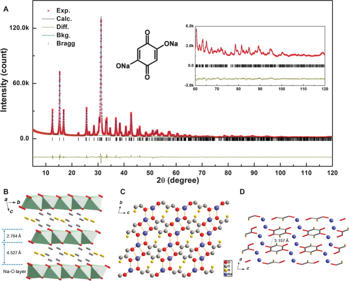
(A) XRD pattern and Rietveld refinement of Na2C6H2O4 sample. The black (red) line represents the experimental (calculated) data. The residual discrepancy is shown in yellow. The refinement is preformed in the P–1 space group. Inset shows the molecular structure. (B to D) Schematic illustration of the triclinic Na2C6H2O4 (B) layered structure (green color refers to Na-O octahedron), (C) along the a axis and (D) along the b axis. For clarity, 2,5-DBQ molecules and sodium ions are expressed using tubes and balls in (D).
The sodium storage behavior of the Na2C6H2O4 electrode in sodium half-cells is shown in Fig. 2A. In the initial discharge process, there is only one flat plateau located at 1.2 V, indicating that sodium insertion happens via a two-phase reaction. Surprisingly, this quinone-type material exhibits a much lower storage voltage than most of other reported similar compounds. At a current rate of C/10, the first discharge capacity is 288 mAh g−1, close to the theoretical value of 291 mAh g−1 based on the assumption of a two-electron redox reaction per molecule (note that C/10 refers to two sodium insertion into Na2C6H2O4 per formula unit in 10 hours). Upon the initial charge process, two voltage plateaus at 1.3 and 1.6 V suggest an asymmetric reaction path in the first cycle. The first charge capacity is 265 mAh g−1, corresponding to a coulombic efficiency of 92%, which is much higher than any other reported organic carbonyl negative electrodes for sodium-ion batteries (table S1) (27–29). This can be attributed to the high storage voltage avoiding SEI formation and sodium consumption, which further ensures high safety and superior rate performance. From the second cycle, there are two plateaus located at 1.3 and 1.2 V in the discharge curves, whereas the charge curves are similar to the first cycle. It implies that both discharge and charge processes in the second cycle are accomplished in two two-phase reactions, which will be further supported by the in situ x-ray diffraction (XRD) results as discussed later. The cyclic voltammetry (CV) curves of the first two cycles for Na2C6H2O4 electrode are displayed in Fig. 2B in the voltage range of 0.8 to 2.0 V versus Na+/Na at a scanning rate of 0.03 mV s−1. On the first negative sweep, a cathodic peak corresponding to the sodium insertion was observed at about 1.0 V. This process is assumed to be the reduction of two quinone groups to form sodium phenoxide. The oxidation process in the subsequent positive sweep shows two anodic peaks centered at 1.4 and 1.7 V, suggesting a two-step oxidation of the sodium phenoxide. In the second cycle, two pairs of redox peaks can be observed in both reduction and oxidation processes, which is in good agreement with the discharge/charge curves in Fig. 2A.
Fig. 2. Sodium storage behavior.
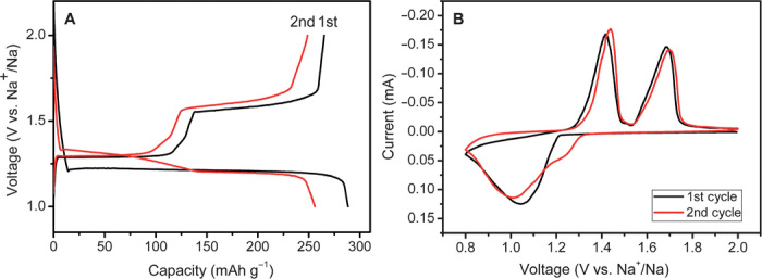
(A) First and second discharge/charge curves of Na2C6H2O4 electrode at a current rate of C/10 (29 mA g−1) in the voltage range of 1.0 to 2.0 V versus Na+/Na. (B) First and second CV curves of Na2C6H2O4 electrode at a scan rate of 0.03 mV s−1.
To understand the structure evolution during sodium insertion and extraction, we performed the electrochemical in situ XRD experiment. Figure 3 (A and B) shows the structure evolution of the Na2C6H2O4 electrode in the first discharge and charge process. At the beginning of discharging, all peaks from the electrode are indexed to triclinic Na2C6H2O4 except for one peak at 18° from the polytetrafluoroethylene (PTFE) binder and a few peaks at 38.5°, 41.2°, and 44° from BeO on the Be window of in situ cell, respectively. The existence of two quinone groups allows for two sodium insertion and extraction. It can be observed that in the initial discharge, Na2C6H2O4 (Na2 phase) converts into Na4C6H2O4 (Na4 phase) through a two-phase reaction, evidenced by a set of Na4 phase peaks emerging at 14.6°, 24.9°, 31.8°, and 37.5° [which can be indexed to be (010), (101), (022), and (121) peaks in the later discussion] and a disappearing of Na2 phase (010), (011), (−111), and (121) peaks at 15.2°, 16.7°, 31°, and 40.6°. The first charge curve is divided into two equal plateaus at 1.3 and 1.6 V, indicating that the two inserted sodium atoms are separately extracted, implying an intermediate radical tri-anion. After charging to 1.4 V, Na4C6H2O4 (Na4 phase) first transforms into an intermediate-phase Na3C6H2O4 (Na3 phase), which is evidenced by the emergence of a new (100) peak at 25.8° and (101) peak at 27.3°. When both two sodium are extracted, the XRD pattern is converted back to the pristine Na2 phase. After the first cycle, the peak shift of Na2 phase is negligible, whereas the relative intensity of some peaks obviously changes, especially (1–11) peak at 2θ=31°. Compared with the XRD pattern of the powder sample, the relative intensity of (1–11) peak is higher in pristine electrode, suggesting that the preferred orientation occurs along the a axis in the composite electrode. After the first discharge and charge processes, the relative intensity is reduced, implying that the length of the a axis declines during the electrochemical reaction. These observations indicate that the first sodium insertion in this material involves a two-phase reaction, whereas the sodium extraction process includes two two-phase reactions. The phase evolution is also in good agreement with the shape of first discharge and charge curves, which consist of one discharge plateau and two charge plateaus, respectively.
Fig. 3. Structure evolution during sodiation and desodiation.
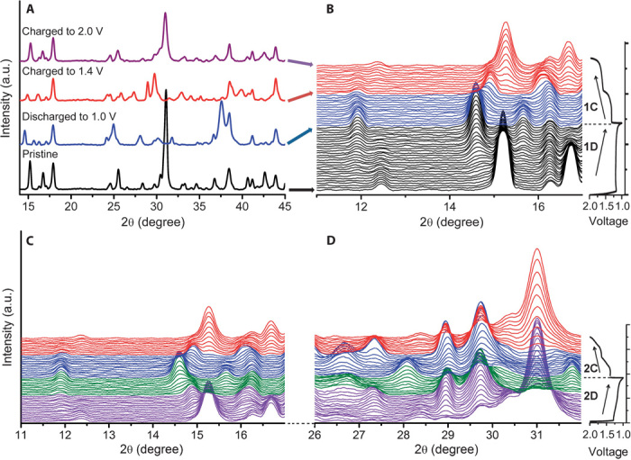
In situ XRD patterns collected during the first and second discharge/charge of the Na/Na2C6H2O4 cell under a current rate of C/20 at the voltage range between 1.0 and 2.0 V. (A and B) Structure evolution in the first cycle. (C and D) Structure evolution processes in the second cycle. a.u., arbitrary units.
In the second cycle, both discharge and charge processes are accomplished through two two-phase reactions (fig. S3). The intermediate-phase Na3C6H2O4 is formed in the first charge process and is then highly reversible in the subsequent cycles, as illustrated in Fig. 3 (C and D). It indicates that the first discharge mechanism is different than that of subsequent electrochemical processes, which may cause the first irreversible loss. From the first charge, the electrode reaction exhibits high structure reversibility and stability, thus ensuring long cycle life. The different reaction paths of the first two cycles are illustrated in Fig. 4.
Fig. 4. Reaction mechanism.
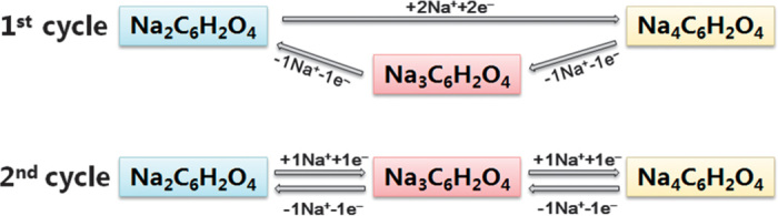
The different reaction paths in the first two cycles of the Na2C6H2O4 electrode.
The fully discharged phase Na4C6H2O4 and the intermediate charged phase Na3C6H2O4 are extremely sensitive to moisture and air. The structures of the two compounds were then resolved directly from the in situ XRD data, by a similar direct space approach used in structure determination of Na2C6H2O4 (see Supplementary Materials S1 for more details). The determined structures can be perfectly fitted to the diffraction pattern with excellent agreement factors. A plot of the observed and calculated intensities of Na3C6H2O4 and Na4C6H2O4 is shown in figs. S4 and S5, and the refined structure parameters are listed in tables S3 and S4.
These two structures adopt the similar centrosymmetric triclinic system and the same space group P–1 as the pristine Na2C6H2O4, with lattice constants of a = 3.444(2) Å, b = 6.159(2) Å, c = 7.708 (2) Å, α = 72.37(2), β = 83.76(2), γ = 89.14(1), V = 154.9 Å3 and a = 3.65(4) Å, b = 6.34(4) Å, c = 7.93(4) Å, α = 71.8(4), β = 77.1(7), γ = 89.7(5), V = 169.6 Å3, respectively.
These three compounds show great structural resemblance and regular evolution of lattice constants. The structure can be described as an alternative stacking of 2,5-DBQ molecular layers with Na-O layers along the c axis. It can be seen from Fig. 5 (A and B) that the layered structure stays intact during Na insertion. It is clear that the inserted sodium atoms are stored in the inorganic layer of Na-O polyhedrons, which also provides a transport pathway for Na+ ions along the ab plane. Upon sodium insertion, the coordination environments of both sodium atoms and carbonyl groups change dramatically. In Na2C6H2O4, all the sodium atoms are coordinated with six oxygen atoms from five adjacent 2,5-DBQ molecules and the carbonyl group is coordinated with three different sodium atoms. Whereas for the fully discharged compound Na4C6H2O4, the two symmetry-independent sodium atoms are each coordinated with five oxygen atoms in a square pyramidal geometry to form the inorganic layer, the coordination number of carbonyl group by sodium atoms is increased to five. The structure of Na3C6H2O4 shows a transient state between the Na2C6H2O4 and Na4C6H2O4 phases. As shown in Fig. 5 (C and D), the three sodium atoms reside in two independent sites within the unit cell of Na3C6H2O4, that is, one Na1 atom (purple, 1g) in six coordinated octahedral environment and two Na2 atoms (pink, 2i) in five coordinated pyramidal environment to form an inorganic layer with alternative octahedrons and square pyramids along the b direction (see more in fig. S6). The change of sodium atom positions in this process is shown in fig. S7. The angle between the identical benzene ring plane and the bc plane decreases with Na insertion, and the benzene ring rotates around its center, as shown in Fig. 6. The distance between neighboring benzene rings significantly expands to 3.282 and 3.734 Å, respectively (note that C-O and C-C lengths are shown in table S5). From the above discussion, Na insertion leads to the obvious movement of all oxygen and benzene rings.
Fig. 5. Crystal structures of Na3C6H2O4 and Na4C6H2O4.
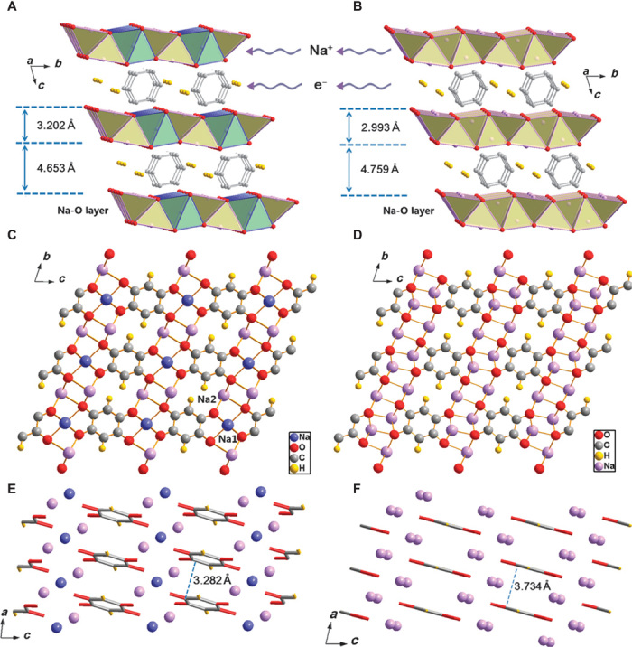
(A to F) Schematic illustration of Na3C6H2O4 (A) layered structure (yellow color refers to Na-O square pyramid, and green color refers to Na-O octahedron), (C) along the a axis and (E) along the b axis, and Na4C6H2O4 (B) layered structure (yellow color refers to Na-O square pyramid), (D) along the a axis and (F) along the b axis. For clarity, 2,5-DBQ molecules and sodium ions are expressed using tubes and balls in (E) and (F).
Fig. 6. Benzene ring rotation.
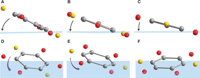
(A to C) Angles between benzene rings and bc plane (blue) in (A) Na2C6H2O4, (B) Na3C6H2O4, and (C) Na4C6H2O4. (D to F) Rotation of benzene rings in (D) Na2C6H2O4, (E) Na3C6H2O4, and (F) Na4C6H2O4.
To investigate the origin of the low Na storage potential, we calculated the total energies of Na2, Na3, and Na4 structures and further obtain the calculated voltage of the reactions. As shown in Table 1, from the total energies of Na2 and Na4 structures, we are able to calculate the theoretical discharge voltage of 1.17 V versus Na+/Na for the electrochemical reaction: Na2C6H2O4 + 2Na → Na4C6H2O4. This matches well with the 1.20 V plateau on the first discharge curve. Similarly, the voltage of the Na3→Na2 reaction predicted by our calculations is 1.38 V, within 0.2 V of the experimental voltage. However, for the Na4→Na3 process, an experimental value of 1.31 V in the first charge is much higher than the calculated voltage (0.95 V), which may be ascribed to an obvious structure distortion from the Na4 phase to the Na3 phase. The polarization between discharge and charge curves was also discussed in Supplementary Materials S2.
Table 1. DFT calculation.
Total energies for Na2C6H2O4, Na3C6H2O4, and Na4C6H2O4 structures and comparison of DFT calculated and experimental reaction voltages.
| Structure | Na2C6H2O4 | Na3C6H2O4 | Na4C6H2O4 | Na |
| Energy (eV/U) | −95.139 | −97.815 | −100.056 | −2.586 |
| Reaction process | Na2→Na4 | Na4→Na3 | Na3→Na2 | |
| Calculated voltage (V versus Na+/Na) | 1.17 | 0.95 | 1.38 | |
| Experimental voltage (V versus Na+/Na) | 1.21 | 1.31 | 1.49 |
On the basis of the resolved structure of the three compounds, the electron and ion transport mechanisms have been investigated via DFT calculations. The change of the electron density near the benzene ring before and after sodium insertion, and the corresponding density of states (DOS) are shown in Fig. 7. It is shown that after sodium insertion, the injected electrons delocalize on the whole benzene ring rather than localizing on carbon-oxygen bonds. The DOS results in Fig. 7 (D to F) also indicate that the injected electrons will occupy the empty orbitals of C2p and O2p. However, variations in the Bader charge values of C2 and C3 atoms are much larger than those of O atoms after sodium insertion, implying that the injected electrons mainly localize on the C2 and C3 atoms (Table 2). These results indicate that in the crystalline state, the redox center is a benzene ring rather than a carbon-oxygen double bond in this quinonyl compound. Benzene rings function similarly to transitional metal in inorganic layered oxides to receive electron.
Fig. 7. Charge compensation mechanism.
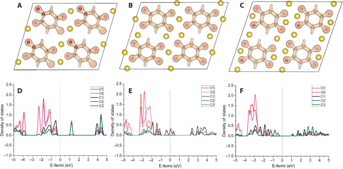
(A to C) Change in the electron density near the benzene ring in Fourier map obtained from the Rietveld refinement (A) Na2C6H2O4, (B) Na3C6H2O4, and (C) Na4C6H2O4. (D to F) DOS for (D) Na2C6H2O4, (E) Na3C6H2O4, and (F) Na4C6H2O4. The Fermi level is set to zero.
Table 2. Bader charge.
Bader charge change in the three structures.
| Structure | Na2C6H2O4 | Na3C6H2O4 | Na4C6H2O4 | |
| Atom | Value charge (e) | Bader charge (e) | Bader charge (e) | Bader charge (e) |
| O1 | 6 | 7.1658 | 7.2198 | 7.2390 |
| O2 | 6 | 7.1647 | 7.1958 | 7.2449 |
| C1 | 4 | 4.0799 | 4.1606 | 4.1575 |
| C2 | 4 | 3.2758 | 3.3697 | 3.5519 |
| C3 | 4 | 3.2522 | 3.3172 | 3.4727 |
To reveal the Na+ ion transport mechanism in this layered structure, we performed molecular dynamics (MD) simulations at six temperatures from 1000 to 2000 K. The trajectories of Na+ ions in pristine Na2C6H2O4 and sodium-inserted Na4C6H2O4 simulated at 1200 K are given in Fig. 8. It is clearly seen that Na+ ion migration pathway in Na2C6H2O4 shows the characteristics of 1D along the a axis. However, after two Na insertions, Na4C6H2O4 is likely 2D along the ab plane. Therefore, the Na+ ions migrate within the Na-O inorganic layer, and no diffusion between the Na-O layer and the benzene layer can be found. In the case of Na3C6H2O4, there is no diffusive behavior but only vibration can be observed even at a high temperature of 2000 K. Both results confirm that Na+ ion transports in the Na-O polyhedral layer, whereas the electron transports through π-stacked benzene rings.
Fig. 8. Na+ ion diffusion mechanism.
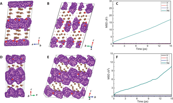
Trajectories (small purple bullets) of Na+ ion in Na2C6H2O4 (A and B) and Na4C6H2O4 (D and E) obtained by the MD simulation at 1200 K for 15 ps. Mean square displacement (MSD) plots of H, C, O, and Na atoms under 1200 K in Na2C6H2O4 (C) and Na4C6H2O4 (F).
DISCUSSION
In conclusion, through resolving the crystal structures and performing DFT calculation, we have demonstrated a new storage mechanism in organic materials with a framework consisting of inorganic Na-O polyhedral layer and organic π-stacked benzene layer: the inorganic layer provides the Na+ ion conduction pathway and storage sites, whereas the organic layer is responsible for the electron conduction and storage. This can be viewed as a new class of robust hosts for Na storage. The proposed storage mechanism is not limited to the specific Na2C6H2O4 example and can be extended to many other carbonyl compounds such as disodium terephthalate (fig. S9), thus opening up a new avenue in the quest of new materials for sodium-ion batteries and the search on new physical and chemical properties of these materials.
MATERIALS AND METHODS
Synthesis
The disodium 2,5-DBQ sample was prepared by a room temperature liquid-phase reaction between stoichiometric 2,5-DBQ (TCI, 98%) and NaOH (99%). NaOH was dissolved in ethanol, and then the solution was slowly injected into a dimethyl sulfoxide solution in which 2,5-DBQ was dissolved. An orange precipitate formed and was separated out by centrifugation. The as-obtained powders were washed by ethanol several times and then dried at 60°C for 12 hours in vacuum.
Characterizations
Powder XRD data were collected on a Bruker D8 x-ray diffractometer with Cu Kα radiation (λ = 1.5405 Å) in a scan range of 5 to 120°. For in situ XRD experiments, beryllium was used as window to allow the penetration of x-ray in the in situ cells. The discharge and charge measurement of in situ cell was carried out on a Land BT2000 battery test system in a voltage range of 1.0 to 2.0 V at C/20 rate.
The morphology of the samples was observed by SEM (Hitachi S-4800). Thermogravimetric (TG) analysis of C6H4O4 and Na2C6H2O4 sample was performed using a Diamond TG thermoanalyzer in the Ar atmosphere.
Electrochemistry
The Na2C6H2O4 electrode was prepared by mixing Na2C6H2O4 (70 wt %), acetylene black (20 wt %), and PTFE (10 wt %) homogeneously and pasting it onto the Al foil and drying at 100°C under vacuum for 10 hours. The CR2032 coin-type cells were assembled with pure sodium foil as the counter electrode and glass fiber as the separator in an argon-filled glove box. The electrolyte is 0.8 M NaPF6 in propylene carbonate. The discharge and charge measurements were carried out on a Land BT2000 battery test system in a voltage range of 1.0 to 2.0 V under room temperature. CV was measured using a CHI627 workstation.
DFT calculation
The DFT calculations were performed using the Vienna ab initio simulation package (30) with the projector augmented-wave method (31). The generalized gradient approximation function parameterized by Perdew-Burke-Ernzerhof (32) was used to describe the exchange-correlation potential. For all calculations, the cutoff of the kinetic energy was set to 520 eV. The geometry optimization was carried out using a 2a × 2b × 2c supercell. The total energy was converged to within 10−5 eV, and the force on each atom was converged to within 0.01 eV/Å. A Γ-centered k-point mesh of 4 × 3 × 2 was used for the Brillouin integrations. The reaction voltage is given by the difference in Gibbs free energies, and it follows that the voltage is given by V = [G(Na2C6H2O4) + nG(Na) − G(Na2+nC6H2O4)]/nq, where n is the charge that is transferred during the reaction. MD simulations were performed in the canonical (NVT) ensemble at six temperatures ranging from 1000 to 2000 K to observe the diffusive behavior for the Na+ ions over the time scale of our simulations. The MD simulations were carried out for 15 ps at each temperature by a Nosé thermostat (36), and a time step of 1 fs is used to integrate the equation of motions. The calculations were performed on a 2 × 2 × 2 supercell. To keep the computational cost at a reasonable level, we used a Γ-centered k-point mesh of 2 × 1 × 1 for the Brillouin zone sampling in MD calculations.
Funding
This work was supported by funding from the National Natural Science Foundation of China (51222210, 11234013, and 51421002), “973” Projects (2012CB932900), and One Hundred Talent Project of the Chinese Academy of Sciences. Author contributions: Y.-S.H. conceived and designed this work. X.W. carried out the synthesis and electrochemical experiments. S.J. refined the XRD results and resolved the crystal structure with X.C. Z.Z. performed all the first-principles calculations. L.J. did the Bader charge analysis. X.W., S.J., and Y.-S.H. wrote the paper. All the authors participated in the analysis of the experimental data and discussions of the results, as well as in preparing the paper. Competing interests: The authors declare that they have no competing interests. Data and materials availability: All data associated with this study is in the body of the manuscript and Supplementary Materials.
SUPPLEMENTARY MATERIALS
Supplementary material for this article is available at http://advances.sciencemag.org/cgi/content/full/1/8/e1500330/DC1
Fig. S1. TG and DSC curves of (A) precursor C6H4O4 and (B) Na2C6H2O4.
Fig. S2. Microstructure of as-prepared Na2C6H2O4.
Fig. S3. Different structure evolution processes between the first and the second cycle.
Structure solution and Rietveld refinement of Na3C6H2O4 and Na4C6H2O4
Fig. S4. XRD pattern and Rietveld refinement of Na3C6H2O4 structure.
Fig. S5. XRD pattern and Rietveld refinement of Na4C6H2O4 structure.
Fig. S6. The positions and coordination environment of sodium atoms in Na2C6H2O4, Na3C6H2O4, and Na4C6H2O4.
Fig. S7. Change of sodium atom local structure during sodium extraction.
Fig. S8. The atomic position illustration of C and O atoms.
Fig. S9. The molecular structure (A) and schematic illustration (B) of the orthorhombic Na2C8H4O4.
Model construction of DFT calculations
Fig. S10. Polarization between discharge and charge.
Fig. S11. UV-vis absorption spectra of Na2C6H2O4.
Fig. S12. The second discharge/charge curves of Na2C6H2O4 at a current rate of C/10.
Table S1. The sodium storage properties for different reported negative electrode materials for sodium-ion batteries.
Table S2. Structural parameters.
Table S3. Structural parameters.
Table S4. Structural parameters.
Table S5. Bond lengths for Na2C6H2O4, Na3C6H2O4, and Na4C6H2O4.
REFERENCES AND NOTES
- 1.Armand M., Tarascon J.-M., Building better batteries. Nature 451, 652–657 (2008). [DOI] [PubMed] [Google Scholar]
- 2.Dunn B., Kamath H., Tarascon J.-M., Electrical energy storage for the grid: A battery of choices. Science 334, 928–935 (2011). [DOI] [PubMed] [Google Scholar]
- 3.Wang Y., Yu X., Xu S., Bai J., Xiao R., Hu Y.-S., Li H., Yang X.-Q., Chen L., Huang X., A zero-strain layered metal oxide as the negative electrode for long-life sodium-ion batteries. Nat. Commun. 4, 2365 (2013). [DOI] [PubMed] [Google Scholar]
- 4.Pan H., Hu Y.-S., Chen L., Room-temperature stationary sodium-ion batteries for large-scale electric energy storage. Energy Environ. Sci. 6, 2338–2360 (2013). [Google Scholar]
- 5.Kim S.-W., Seo D.-H., Ma X., Ceder G., Kang K., Electrode materials for rechargeable sodium-ion batteries: Potential alternatives to current lithium-ion batteries. Adv. Energy Mater. 2, 710–721 (2012). [Google Scholar]
- 6.Slater M. D., Kim D., Lee E., Johnson C. S., Sodium-ion batteries. Adv. Funct. Mater. 23, 947–958 (2013). [Google Scholar]
- 7.Chevrier V. L., Ceder G., Challenges for Na-ion negative electrodes. J. Electrochem. Soc. 158, A1011–A1014 (2011). [Google Scholar]
- 8.Stevens D. A., Dahn J. R., High capacity anode materials for rechargeable sodium-ion batteries. J. Electrochem. Soc. 147, 1271–1273 (2000). [Google Scholar]
- 9.Komaba S., Murata W., Ishikawa T., Yabuuchi N., Ozeki T., Nakayama T., Gotoh K., Fujiwara K., Electrochemical Na insertion and solid electrolyte interphase for hard-carbon electrodes and application to Na-ion batteries. Adv. Funct. Mater. 21, 3859–3867 (2011). [Google Scholar]
- 10.Li Y., Xu S., Wu X., Yu J., Wang Y., Hu Y.-S., Li H., Chen L., Huang X., Amorphous monodispersed hard carbon micro-spherules derived from biomass as a high performance negative electrode material for sodium-ion batteries. J. Mater. Chem. A 3, 71–77 (2015). [Google Scholar]
- 11.Senguttuvan P., Rousse G., Seznec V., Tarascon J.-M., Palacín M. R., Na2Ti3O7: Lowest voltage ever reported oxide insertion electrode for sodium ion batteries. Chem. Mater. 23, 4109–4111 (2011). [Google Scholar]
- 12.Pan H., Lu X., Yu X., Hu Y.-S., Li H., Yang X.-Q., Chen L., Sodium storage and transport properties in layered Na2Ti3O7 for room-temperature sodium-ion batteries. Adv. Energy Mater. 3, 1186–1194 (2013). [Google Scholar]
- 13.Sun Y., Zhao L., Pan H., Lu X., Gu L., Hu Y.-S., Li H., Armand M., Ikuhara Y., Chen L., Huang X., Direct atomic-scale confirmation of three-phase storage mechanism in Li4Ti5O12 anodes for room-temperature sodium-ion batteries. Nat. Commun. 4, 1870 (2013). [DOI] [PubMed] [Google Scholar]
- 14.Delmas C., Cherkaoui F., Nadiri A., Hagenmuller P., A nasicon-type phase as intercalation electrode: NaTi2(PO4)3. Mater. Res. Bull. 22, 631–639 (1987). [Google Scholar]
- 15.Chen H., Armand M., Demailly G., Dolhem F., Poizot P., Tarascon J.-M., From biomass to a renewable LiXC6O6 organic electrode for sustainable Li-ion batteries. ChemSusChem 1, 348–355 (2008). [DOI] [PubMed] [Google Scholar]
- 16.Armand M., Grugeon S., Vezin H., Laruelle S., Ribière P., Poizot P., Tarascon J.-M., Conjugated dicarboxylate anodes for Li-ion batteries. Nat. Mater. 8, 120–125 (2009). [DOI] [PubMed] [Google Scholar]
- 17.Liang Y., Tao Z., Chen J., Organic electrode materials for rechargeable lithium batteries. Adv. Energy Mater. 2, 742–769 (2012). [Google Scholar]
- 18.Song Z., Zhou H., Towards sustainable and versatile energy storage devices: An overview of organic electrode materials. Energy Environ. Sci. 6, 2280–2301 (2013). [Google Scholar]
- 19.Zeng R.-H., Li X.-p., Qiu Y.-c., Li W.-s., Yi J., Lu D.-s., Tan C.-l., Xu M.-q., Synthesis and properties of a lithium-organic coordination compound as lithium-inserted material for lithium ion batteries. Electrochem. Commun. 12, 1253–1256 (2010). [Google Scholar]
- 20.Song Z., Zhan H., Zhou Y., Anthraquinone based polymer as high performance cathode material for rechargeable lithium batteries. Chem. Commun. 4, 448–450 (2009). [DOI] [PubMed] [Google Scholar]
- 21.Sakaushi K., Hosono E., Nickerl G., Gemming T., Zhou H., Kaskel S., Aromatic porous-honeycomb electrodes for a sodium-organic energy storage device. Nat. Commun. 4, 1485 (2013). [DOI] [PubMed] [Google Scholar]
- 22.Deng W., Liang X., Wu X., Qian J., Cao Y., Ai X., Feng J., Yang H., A low cost, all-organic Na-ion battery based on polymeric cathode and anode. Sci. Rep. 3, 2671 (2013). [DOI] [PMC free article] [PubMed] [Google Scholar]
- 23.Yao M., Kuratani K., Kojima T., Takeichi N., Senoh H., Kiyobayashi T., Indigo carmine: An organic crystal as a positive-electrode material for rechargeable sodium batteries. Sci. Rep. 4, 3650 (2014). [DOI] [PMC free article] [PubMed] [Google Scholar]
- 24.Liang Y., Zhang P., Chen J., Function-oriented design of conjugated carbonyl compound electrodes for high energy lithium batteries. Chem. Sci. 4, 1330–1337 (2013). [Google Scholar]
- 25.Hong J., Lee M., Lee B., Seo D.-H., Park C. B., Kang K., Biologically inspired pteridine redox centres for rechargeable batteries. Nat. Commun. 5, 5335 (2014). [DOI] [PubMed] [Google Scholar]
- 26.Yao M., Senoh H., Yamazaki S.-i., Siroma Z., Sakai T., Yasuda K., High-capacity organic positive-electrode material based on a benzoquinone derivative for use in rechargeable lithium batteries. J. Power Sources 195, 8336–8340 (2010). [Google Scholar]
- 27.Zhao L., Zhao J., Hu Y.-S., Li H., Zhou Z., Armand M., Chen L., Disodium terephthalate (Na2C8H4O4) as high performance anode material for low-cost room-temperature sodium-ion battery. Adv. Energy Mater. 2, 962–965 (2012). [Google Scholar]
- 28.Sakaushi K., Nickerl G., Wisser F. M., Nishio-Hamane D., Hosono E., Zhou H., Kaskel S., Eckert J., An energy storage principle using bipolar porous polymeric frameworks. Angew. Chem. Int. Ed. 51, 7850–7854 (2012). [DOI] [PubMed] [Google Scholar]
- 29.Wang S., Wang L., Zhu Z., Hu Z., Zhao Q., Chen J., All organic sodium-ion batteries with Na4C8H2O6. Angew. Chem. Int. Ed. 53, 5892–5896 (2014). [DOI] [PubMed] [Google Scholar]
- 30.Kresse G., Furthmüller J., Efficiency of ab-initio total energy calculations for metals and semiconductors using a plane-wave basis set. Comput. Mater. Sci. 6, 15–50 (1996). [DOI] [PubMed] [Google Scholar]
- 31.Blöchl P. E., Projector augmented-wave method. Phys. Rev. B Condens. Matter 50, 17953–17979 (1994). [DOI] [PubMed] [Google Scholar]
- 32.Perdew J. P., Burke K., Ernzerhof M., Generalized gradient approximation made simple. Phys. Rev. Lett. 77, 3865–3868 (1996). [DOI] [PubMed] [Google Scholar]
- 33.Alcántara R., Jaraba M., Lavela P., Tirado J. L., NiCo2O4 spinel: First report on a transition metal oxide for the negative electrode of sodium-ion batteries. Chem. Mater. 14, 2847–2848 (2002). [Google Scholar]
- 34.Jow T. R., Shacklette L. W., Maxfield M., Vernick D., The role of conductive polymers in alkali-metal secondary electrodes. J. Electrochem. Soc. 134, 1730–1733 (1987). [Google Scholar]
- 35.Xiao L., Cao Y., Xiao J., Wang W., Kovarik L., Nie Z., Liu J., High capacity, reversible alloying reactions in SnSb/C nanocomposites for Na-ion battery applications. Chem. Commun. 48, 3321–3323 (2012). [DOI] [PubMed] [Google Scholar]
- 36.Martyna G. J., Klein M. L., Tuckerman M., Nosé–Hoover chains: The canonical ensemble via continuous dynamics. J. Chem. Phys. 97, 2635–2643 (1992). [Google Scholar]
Associated Data
This section collects any data citations, data availability statements, or supplementary materials included in this article.
Supplementary Materials
Supplementary material for this article is available at http://advances.sciencemag.org/cgi/content/full/1/8/e1500330/DC1
Fig. S1. TG and DSC curves of (A) precursor C6H4O4 and (B) Na2C6H2O4.
Fig. S2. Microstructure of as-prepared Na2C6H2O4.
Fig. S3. Different structure evolution processes between the first and the second cycle.
Structure solution and Rietveld refinement of Na3C6H2O4 and Na4C6H2O4
Fig. S4. XRD pattern and Rietveld refinement of Na3C6H2O4 structure.
Fig. S5. XRD pattern and Rietveld refinement of Na4C6H2O4 structure.
Fig. S6. The positions and coordination environment of sodium atoms in Na2C6H2O4, Na3C6H2O4, and Na4C6H2O4.
Fig. S7. Change of sodium atom local structure during sodium extraction.
Fig. S8. The atomic position illustration of C and O atoms.
Fig. S9. The molecular structure (A) and schematic illustration (B) of the orthorhombic Na2C8H4O4.
Model construction of DFT calculations
Fig. S10. Polarization between discharge and charge.
Fig. S11. UV-vis absorption spectra of Na2C6H2O4.
Fig. S12. The second discharge/charge curves of Na2C6H2O4 at a current rate of C/10.
Table S1. The sodium storage properties for different reported negative electrode materials for sodium-ion batteries.
Table S2. Structural parameters.
Table S3. Structural parameters.
Table S4. Structural parameters.
Table S5. Bond lengths for Na2C6H2O4, Na3C6H2O4, and Na4C6H2O4.