Abstract
This paper presents a novel plug-in nanoliter liquid dispensing system with a plug-and-play interface for simple and reversible, yet robust integration of the dispenser. A plug-in type dispenser was developed to facilitate assembly and disassembly with an actuating part through efficient modularization. The entire process for assembly and operation of the plug-in dispenser is performed via the plug-and-play interface in less than a minute without loss of dispensing quality. The minimum volume of droplets pneumatically dispensed using the plug-in dispenser was 124 nl with a coefficient of variation of 1.6%. The dispensed volume increased linearly with the nozzle size. Utilizing this linear relationship, two types of multinozzle dispensers consisting of six parallel channels (emerging from an inlet) and six nozzles were developed to demonstrate a novel strategy for volume gradient dispensing at a single operating condition. The droplet volume dispensed from each nozzle also increased linearly with nozzle size, demonstrating that nozzle size is a dominant factor on dispensed volume, even for multinozzle dispensing. Therefore, the proposed plug-in dispenser enables flexible design of nozzles and reversible integration to dispense droplets with different volumes, depending on the application. Furthermore, to demonstrate the practicality of the proposed dispensing system, we developed a pencil-type dispensing system as an alternative to a conventional pipette for rapid and reliable dispensing of minute volume droplets.
I. INTRODUCTION
The technology used for dispensing minute volumes of liquids at a desired location has emerged as one of the significant technologies that have been employed in various applications, such as those in cell biology, biochips, and drug screening.1–3 By handling minute liquid volumes, liquid dispensers provide an economic, rapid, and flexible way to save materials, providing a parallel process and compatibility for various substrates.4,5 To dispense liquids in minute volumes, dispensers have been developed for use with different actuating methods such as thermal-bubble, piezoelectric, pneumatic, and solenoid actuation.6–10 Although commercial dispensers have high reliability and accuracy, there is the inevitable issue of channel clogging induced as a result of the narrow liquid paths inside the dispenser and various liquid properties.11,12 Therefore, frequent maintenance is required. Depending on the intended application, different ranges of dispensing volumes are required, and the dispenser may need to be replaced by a nozzle of increased or decreased size; this is invariably associated with high cost, thereby leading to high unit prices for commercial dispensers. Therefore, a growing interest in liquid dispenser technology is high disposability as in conventional pipetting but with a lower volume, thereby broadening utilization in various applications.
In manufacturing dispensers, integration of the dispensing system parts (dispenser, reservoir, actuating part, etc.) is essential for ensuring no leakage during performance. In general, irreversible bonding methods, including UV glue, epoxy, and plasma treatment, are performed for the permanent integration of the dispenser. This permanent connection limits the scalability of the volume range owing to the fixed nozzle size. To actively control the dispensing volume range, dispensers must have interchangeable nozzles for reversible integration. Few methods have been implemented for dispensing system integration in a reversible manner. Specifically, clamping and thread-tightening have been chosen previously.8–10 However, the reported integration procedures are cumbersome and time-consuming and hinder prompt operation. For this reason, the need for simplicity of integration has been increasing. Simple, reversible, yet robust connecting methods maintaining nonleaking performance are required for user-friendly nozzle replacement as with pipetting tips.
In this work, we present a plug-in liquid dispenser with a plug-and-play interface (i.e., the dispensing system is in operation as soon as it is connected) to allow disposability and simple replacement of the dispenser while retaining nanoliter dispensing performance. For reversible integration of the dispenser, we developed a plug-socket type, macro-to-micro connector, and characterized its nonleaking performance according to the plug dimension and operating parameters. Although plug-socket connectors have been introduced for easy macro-to-micro connections in the field of microfluidics,13–15 the present effort is, to the best of our knowledge, the first to modularize a dispensing system with a plug-socket connector. A plug-in dispenser made of polydimethylsiloxane was fabricated using replica molding and was characterized with various nozzle sizes and pressures as the design and operation parameters, respectively. Based on the design flexibility of the fabrication method and the dispensing mechanism, multinozzle dispensers at different nozzle dimensions were developed, and their volume gradient dispensing strategy was demonstrated at a single operating condition. Moreover, a compact pencil-type dispensing system was proposed and presented to illustrate its practicality in terms of its better dispensing capability, including dispensing accuracy and minimum volume to be dispensed, than the conventional pipetting technique.
II. DESCRIPTION OF SYSTEM AND OPERATION
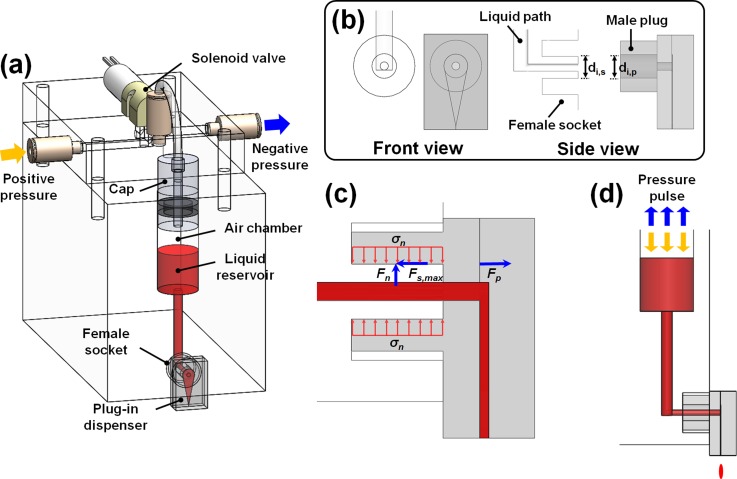
The plug-in nanoliter liquid dispensing module consists of the cartridge and plug-in dispenser. The cartridge is composed of a female socket, liquid reservoir, detachable cap, and a solenoid valve, switching the positive and negative pressures in the liquid reservoir (Fig. 1(a)). The plug-in dispenser, which is inserted into the female socket, is composed of a microchannel part, including the inlet, microchannel, nozzle, and a plug part for integration (Fig. 1(b)). The plug connected to the socket completes the liquid path from the liquid reservoirs of the cartridge to the nozzle of the dispenser. The male plug and female socket, which are analogous to an electric plug and socket, are designed for easily reversible connection and realization of the plug-and-play interface. Figure 1(c) illustrates the liquid sealing mechanism through the plug-socket connection. The inner diameter (di,p) of the plug is designed to be smaller compared to the inner diameter (di,s) of the socket. The elastic plug is inserted with a radial expansion and is fixed on the surface of the rigid socket. Tensile stress (σn) is then induced in the plug by compression, resulting in a repulsive force perpendicular to the contact surface. The maximum static friction force (Fs,max) that obstructs the object's movement along the surface is proportional to the normal force (i.e., the repulsive force Fn). The static friction force is exerted on the opposite side as a frictional resistance against the force (Fp) and holds the plug dispenser on the socket during liquid dispensing. Moreover, Fp exerted on the dispenser is induced from the stress (e.g., longitudinal, circumferential, and radial) that is applied to the wall owing to the internal pressurization of the liquid channel. Therefore, a plug-socket connection is realized through the optimization of the plug-and-socket design to attain sufficient static friction force.
FIG. 1.
Schematic views of a plug-in nanoliter dispensing module. (a) Dispensing module overview; (b) front and side views of female socket and dispenser with male plug; (c) liquid sealing mechanism through plug-socket connection; (d) dispensing mechanism.
The mechanism for plug-in dispensing is illustrated in Fig. 1(d). The proposed plug is made of an elastic material, such as polydimethylsiloxane (PDMS), and can be repeatedly inserted and removed owing to the elastic deformation of the material. As soon as the plug-in dispenser is connected to the cartridge, the liquid from the reservoir fills the dispenser under pressurization of the air chamber. At this time, the capillary force at the end of the narrow nozzle prevents an overflow. The air chamber is normally maintained at low negative values or at atmospheric pressure. Positive pressure overcoming the capillary force is applied to eject the liquid through the nozzle. The dispensing volume is regulated by the air chamber pressure profile determined by the operating parameters, including the amplitude and application times of positive and negative pressures (push time for positive and pull time for negative pressure). The pulsed electric signal under the control of software (LabVIEW 2014) switches the positive and negative pressures that are developed within the air chamber. The pulsed pressure generates numerous droplets in a drop-on-demand (DOD) generation mode.
III. EXPERIMENTAL
A. Design and fabrication of dispensing module
The dispensing module consists of the liquid cartridge and the plug-in dispenser. The cartridge was fabricated from acrylic using a computer numerical control (CNC) milling machine. In the cartridge, the donut-shaped female socket has a 5.0-mm depth, and 7.5- and 3.0-mm outer and inner diameters, respectively. At the center of the female socket, a 1-mm diameter through-hole path is also fabricated to form a liquid channel from the liquid reservoir to the inlet of the dispenser.
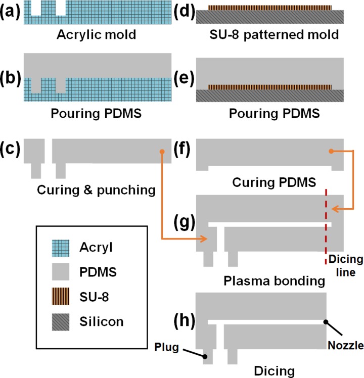
The plug-in dispenser was made of PDMS using a replica molding technique16 and consists of two layers. One of them is the male plug part, and the other is the microchannel part that includes the nozzle (Fig. 2). For the plug part, acrylic structures machined with CNC milling were used as the master mold. The mixture of PDMS prepolymer and curing agent in the ratio of 10:1 (w/w) was poured on the mold and was then cured in an oven at 60 °C for 2 h. The plug-patterned PDMS layer was detached from the mold after it had cooled. Note that the cooling procedure is mandatory to avoid tearing during the detachment, owing to the thermal expansion property of PDMS. Using a biopsy punch with a 1.5-mm diameter, the center of the plug was punched to build a liquid inlet. The dimensions of the plug's outer diameter and length were fixed at 6.5 and 5.0 mm, respectively. We decreased the inner diameters from 3.0 to 2.6 mm in 0.1-mm increments. Thus, various male plugs with a donut shape and with different inner diameters but with fixed outer diameter and length were fabricated. For the microchannel part, the master mold was fabricated by photolithography to pattern microstructures of a negative photoresist (KMPR 1025, Microchem. Corp.) on a 4-in. silicon wafer. The master mold of the microchannel part was 60 μm in height. The rest of the fabrication followed the methodology used for the plug part. The two layers fabricated were bonded by O2 plasma treatment at 45 W for 35 s, under 67 Pa O2 pressure. After bonding, the assembly was incubated at 60 °C over 24 h to recover its surface properties (including hydrophobicity) and to ensure a firm bond between the surfaces of the layers. Then, nozzles were defined under the guidance of aligned marks with a microscope using the self-built cutting tool (see Fig. S1 in the supplementary material).17 For the single nozzle dispenser, the nozzles had widths of 40, 60, 80, 100, 120, and 140 μm, and their length and height were fixed as 500 and 60 μm, respectively (see Fig. S2 in the supplementary material).17 For the multinozzle dispenser, six nozzles split from an inlet were integrated in a dispenser. Two multinozzle dispenser types were designed. The first one had nozzles with the same width size of 40 μm. The other had nozzles with different width sizes ranging from 40 to 140 μm in 20-μm increments.
FIG. 2.
Plug-in dispenser fabrication process.
B. Experimental setup
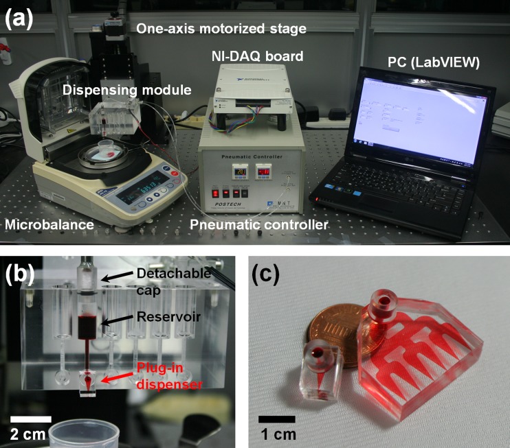
The experimental setup consisted of the dispensing module, a one-axis motorized stage, a microbalance, a pneumatic controller, a NI-DAQ board, and a PC for execution of the LabVIEW software (Fig. 3(a)). Under the monitoring of the two pressure gauges with a resolution of 0.1 kPa, the pneumatic controller precisely provided the required positive and negative pressures from the diaphragm pumps (Hargraves Technology Corp., USA for positive pressure, and KNF Neuberger Ltd., Germany, for negative pressure). To trigger the solenoid valve (with a response time of 1 ms), an electric pulse signal was controlled through LabVIEW and the data acquisition device (NI-DAQ USB-6251). To analyze the dispensed volume, a microbalance with a weight resolution of 0.1 mg (A&D Ltd., Japan) was used to measure the mass of dispensed droplets,18 which were collected in a silicone oil bath to prevent evaporation. The figure in units of mass was converted to one in units of volume based on the density. This measurement had an error below 1%. All experimental grayscale images were obtained using a CCD camera mounted on an inverted microscope (Olympus CKX41). All color images were obtained using a DSLR camera (Canon Corp., Japan).
FIG. 3.
Experimental setup for the plug-in dispensing system and dispensing characterization. (a) Overall experimental setup; (b) detailed view of the dispensing module; (c) single (left) and multiple (right) plug-in dispensers.
IV. RESULTS AND DISCUSSION
A. Characterization of plug inner diameter via burst pressure test
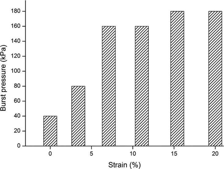
To prove the validity of the plug-socket connection experimentally, a burst pressure test was conducted. The burst pressure is defined as the pressure at which the liquid in the module leaks owing to the detachment of the plug-in dispenser from the socket. Since the maximum static friction increases proportionally to the tensile stress along the radial axis, it was expected that bust pressure would increase as the strain of the plugs increase based on the stress–strain relationship characterizing elastic deformation. The strain is defined simply as the ratio of the variance between the initial and the final diameters (ri,p) of the plug to the initial diameter of the plug. Inner plug diameters of 3.0, 2.9, 2.8, 2.7, 2.6, and 2.5 mm resulted in strains of 0, 3.4, 7.1, 11.1, 15.4, and 20%, respectively. The burst pressures were investigated with the 140-μm nozzle width dispensers at different strains to optimize plug-socket connector performance (Fig. 4). The increase in the maximum static friction (Fs,max) with the decrease in the plug's inner diameter was confirmed. The burst pressure was gradually increased until 7% strain was attained and was maintained at values within the range of 160–180 kPa. The saturation of the burst pressure is explained in a reasonable way. Incomplete insertion occurred because the elastic restoring force of the material increased as the inner diameter of the inserted plugs decreased, resulting in reduction of the maximum static friction. There was no significant variance in the burst pressure as the nozzle width was varied from 40 to 140 μm (see Fig. S3 in the supplementary material).17 Therefore, the maximum burst pressure was determined to be 180 kPa. Based on the result of the burst pressure test, a 2.8-mm inner diameter was selected for the rest of the experiments for easy insertion.
FIG. 4.
Characterization of the burst pressure at which liquid leaks with strain induced from the inner diameters of the dispenser plug. The data were obtained from five repeated experiments in the pressure range of 0–200 kPa, with increments of 20 kPa.
B. The effect of air chamber volume on dispensed droplet volume
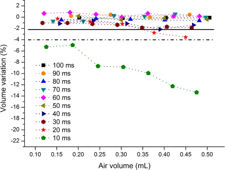
Liquid dispensing occurs because of the pressure difference between the air chamber and the nozzle of the dispenser that is induced by pressurization of the air chamber inside the liquid reservoir. Thus, the dispensed volume is dependent on the internal pressure profile of the air chamber. The pressurization inside the air chamber occurs as a result of the sequential process of pressure transfer though the solenoid valve, tube line, and air chamber. During pressurization, there is a delay time over which the developed pressure fully reaches the set pressure, depending on the volume of the air chamber and the flow capacity of the pressure source.19,20 Accordingly, the volume increment of the air chamber in the liquid reservoir (during dispensing) causes a volume variation among droplets dispensed under the same operating conditions. To investigate this predictable result, the dispensed volume was measured based on the volume increment of the air chamber and at different push times from 10 to 100 ms for pressurization (by positive pressure transferred from the solenoid valve). Subsequently, the volume error was analyzed. For efficient experiments, a plug-in dispenser with a large nozzle—120 μm in width—was used because the air chamber volume expands relatively rapidly when large-volume droplets are dispensed. Positive and negative pressures were fixed at 100 kPa (with a flow capacity of ∼10.5 l/min at this pressure) and at −1 kPa, respectively. The pull time for pressurization by negative pressure was fixed at 100 ms, which is enough to return to the initial state (i.e., the initial position of the interface between liquid and air). In addition, the initial air volume in the air chamber was maintained at ∼250 μl for each experiment. The air chamber is defined as the space between the inlet of the solenoid valve and the liquid surface of the liquid reservoir. To minimize measurement error, the dispensed volume was averaged over 100 droplets. Figure 5 shows the dispensed volume variation according to the increment of the air volume. The dispensed volume variation is the fractional change in dispensed volume from the initially dispensed volume (Equation (1))
| (1) |
where vi is the dispensed volume at the beginning and vl is the dispensed volume following subsequent operation. In the case of a 10-ms push time, a decrease in the dispensed volume is clearly observed with the increase in air volume at the same operating conditions. As push time increases, the effect of the air volume on the dispensed volume variation decreases. If we assume that the total dispensing volume (i.e., increased volume of the air chamber) is less than 0.5 ml, allowable variations less than 2 and 4% require push times of more than 30 and 20 ms, respectively. This factor can be improved with the higher-capacity pumping or the use of an additional device to continually supply liquid into the reservoir. Based on the dispensing characteristics, we chose a total dispensing volume of 0.3 ml and push times of more than 20 ms for the following experiments. The applied positive pressure was limited to values under 100 kPa because the flow capacity was reduced as the pressure increased.
FIG. 5.
Characterization of dispensed volume variation against the air chamber volume in the liquid reservoir at different push times for pressurization using 100 kPa of positive pressure. Solid and dashed-dotted-dashed lines refer to the range of −2 and −4% volume variation, respectively.
C. Effects of applied pressure and nozzle width on dispensed volume
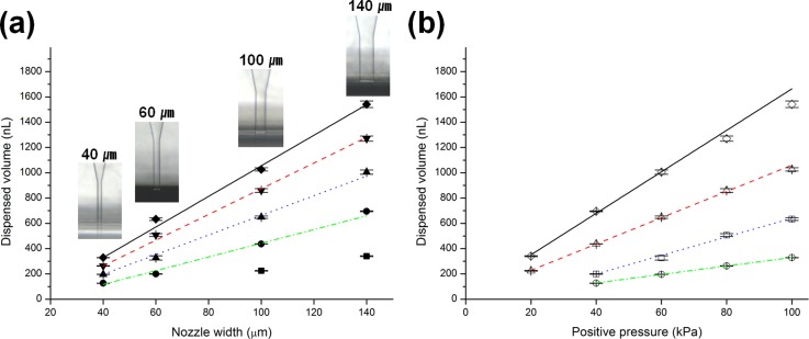
To evaluate dispensing performance and the minimum dispensing volume of the nanoliter plug-in dispenser, the dispensed volume was quantified depending on two parameters: nozzle width and applied positive pressure. Before the performance test, a repeatability test was conducted to confirm the system's volume dispensing reliability. With a 40-μm nozzle width dispenser, numerous dispensed droplets (12 200 droplets) under specific operating conditions (positive pressure of 40 kPa, push time of 20 ms, negative pressure of −1 kPa, pull time of 150 ms) were evaluated to an average volume of 124 nl with a coefficient of variation of 1.6%. Figure 6(a) illustrates the dispensing characterization with the different nozzle widths, at 40, 60, 100, and 140 μm. Positive pressures of 20, 40, 60, 80, and 100 kPa were also applied for each nozzle. Subsequently, the negative pressure and push time was fixed at −1 kPa and 20 ms, respectively. The dispensed volume tended to decrease linearly with decreasing nozzle width at the given pressures. With the 40- and 60-μm nozzle dispensers, wetting occurred at the end of nozzle at 20 kPa and liquid ejection failed. A narrower nozzle required more energy to eject liquid owing to the increase in hydraulic resistance and the capillary force associated with the narrower nozzle. With a 20-μm nozzle dispenser, wetting phenomena also occurred in the range of positive pressures up to 100 kPa (data not included). The nozzle wetting can be reduced by modifying the geometry and wettability of the nozzle. For example, a super-hydrophobic21 and/or sharped nozzle22 decreases the minimum dispensed volume. Alternatively, smaller volumes can be generated under a shorter push time (i.e., less than 20 ms), and a pneumatic pump with a higher flow capacity or an additional refilling system is required for stable operation with regard to the reproducibility of the dispensing volume. For the current system configuration, the minimum volume of our system was thus evaluated to be 124 nl. The dispensed volume gradient increased gradually with applied pressure. Figure 6(b) also shows a linear increment of the dispensed volume according to the increment of the applied pressure. Thus, based on this result, the dispensed volume can be estimated depending on the applied pressures and nozzle widths. In accordance with this linear relationship, the nozzle can be designed simply based on various target volumes, depending on their applications.
FIG. 6.
Characterization of dispensed volume. (a) Nozzle effect at given positive pressures (insets show different nozzles at microscopic views and the symbols ▪, ●, ▲, ▼, and ◆ indicate 20, 40, 60, 80, and 100 kPa of positive pressures); (b) positive pressure effect at given dispensers with different nozzles (○, □, △, and ◇ indicate 40, 60, 100, and 140 μm nozzle widths, respectively). In this figure, solid (black), dashed (red), dotted (blue), and dashed-dotted-dashed (green) lines indicate linear fits of the data.
D. Volume gradient liquid dispensing using a multinozzle plug-in dispenser
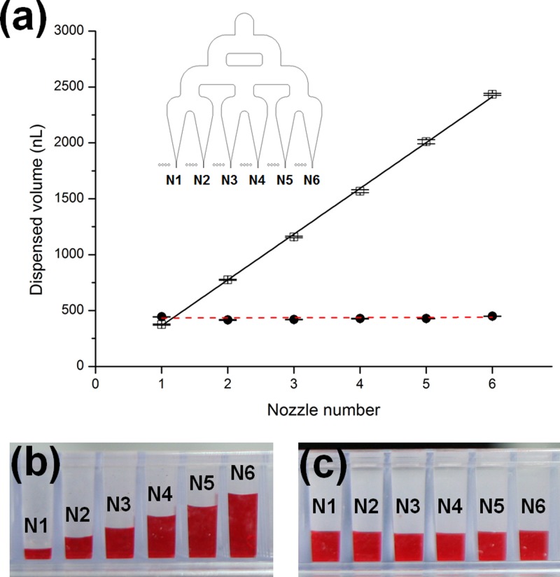
The dispensed volume exhibits a linear relationship with nozzle width as mentioned in Section IV C. In this respect, we developed a novel strategy for volume gradient dispensing using a multinozzle plug-in dispenser with a combination of different nozzle widths. The blueprint for the multinozzle dispenser is shown in Fig. 7(a). The nozzles are located at each end of the multichannels sequentially splitting from the inlet. To validate our strategy experimentally, two types of a dispenser with six nozzles were fabricated, and dispensed volumes of each nozzle were characterized. The nozzle widths of one of the dispensers were increased from 40 to 140 μm in 20 μm increments (40-to-140 dispenser) and the other had the same sizes at 40 μm (40-to-40 dispenser). Figure 7(a) demonstrates the dispensed volume through each nozzle from N1 to N6, under a specified operating condition. The operating conditions for positive and negative pressures, push time, and pull time were maintained as 50 kPa, −1 kPa, 50 ms, and 1 s, respectively. For the measurement of each nozzle, a plate with a hole allowed passage of the droplet to be measured from the nozzle, and blocked passing droplets from the other nozzles located between the microbalance and the dispensing module. Thus, the dispensed volume from each nozzle was measured, while the other nozzles continued to generate droplets. In the 40-to-40 dispensers, the average volume of the droplets dispensed from the six nozzles and the standard deviation among the nozzles were 431 and ±12.9 nl, respectively. This indicates that the energy (i.e., pressure) applied to the liquid reservoir is evenly transferred to each nozzle through the split channels from the inlet. The 40-to-140 dispenser generates 375 (CV = 1.5%), 775 (CV = 0.5%), 1158 (CV = 0.6%), 1568 (CV = 0.9%), 2011 (CV = 1%), and 2434 nl (CV = 0.4%) from nozzles with widths of 40, 60, 80, 100, 120, and 140 μm, respectively. The dispensed volume increased linearly according to the nozzle widths. This result matches the tendency observed for the single nozzle dispensing experiment. Note that the linear relationship between the dispensed volume and the nozzle width is valid under the application of the same amplitude of positive pressure (see Fig. 6(a)). This means that the energy is also evenly transferred from the inlet, i.e., the influence of the nozzle width is insignificant on transferring energy, but dispensed volume is still dependent on the nozzle width. By simply controlling the nozzle widths, the gradient of the volume of dispensed droplets can be regulated, and the dispensing volume can be easily estimated as in the single nozzle dispenser case. Figures 7(b) and 7(c) show the results after dispensing red-dyed water in a commercialized 384 well-plate. In Fig. 7(b), 30 droplets were dispensed with a 40-to-140 dispenser, and in Fig. 7(c), 100 droplets were dispensed with a 40-to-40 dispenser. The proposed multinozzle dispenser can dispense multiple droplets with a linear volume gradient at a single operation. This helps the system configuration to be more efficient compared to the parallelization of single nozzle dispensers, i.e., there is no additional requirement of actuation parts, including a liquid reservoir, cap, solenoid valve, and pressure lines.
FIG. 7.
Volume gradient dispensing at a single operating condition. (a) Characterization of dispensed volume of two types of multinozzle dispenser (blueprint is inserted as an inset, symbols ● and □ indicate 40-to-40 and 40-to-140 dispensers, respectively, and dashed (red) and solid (black) lines indicate linear fits of data); (b) 30 droplets collected with a 40-to-140 dispenser; (c) 100 droplets collected with a 40-to-40 dispenser that resulted in a 384 well-plate.
E. Pencil-type dispensing system
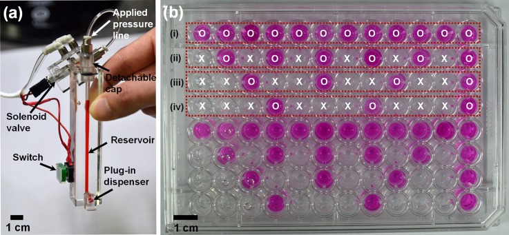
To validate our liquid dispensing mechanism as a practical method, we developed a compact pencil-type dispensing system that can be utilized as an alternative to conventional pipettes in the small volume range; this is because the conventional pipetting technique lacks the capability of dispensing minute-volume droplets (less than a few microliters). The features of the plug-in dispenser were integrated into the pencil dispensing module as a miniature version (Fig. 8(a)). For a finger-touch-based on-demand operation, an electric switch for transmitting an electric signal that would trigger the solenoid valve was additionally integrated in the module. Based on the results of the variation of the dispensed volume with a variation in the air chamber volume as presented in Section IV B, a reservoir with a smaller chamber volume of 300 μl was designed to reduce the performance degradation caused by volume variation under the air volume effect, rather than integrating an additional liquid refill system into the module. To validate the performance of the developed pencil dispensing system with a 40-μm nozzle dispenser, we measured the volume of dispensed droplets for consuming all the loaded liquid and obtained an average volume of 125 nl with a coefficient of variation of 3.6% under the set operating conditions (positive pressure of 40 kPa, push time of 20 ms, and negative pressure of −1 kPa). The test results are consistent with the results of the repeatability test presented in Section IV C. It was confirmed that the dispensing performance was retained even in the miniaturized version. To visualize finger-touch-based on-demand dispensing, we dispensed a droplet of sodium hydroxide (NaOH) solution (1 M in DI water) into desired wells of a 96-well plate. We preloaded 200 μl of 2.5 mM phenolphthalein solution in each well of the well plate by pipetting. A droplet was dispensed in every well (first column), every two wells (second column), every three wells (third column), and every four wells (fourth column) under the set operating conditions (positive pressure of 40 kPa, push time of 20 ms, negative pressure of −1 kPa). Rapid delivery of the droplet of sodium hydroxide solution into the wells was achieved, and as a result, the preloaded phenolphthalein solution turned from colorless to red in color (Fig. 8). Therefore, the developed pencil-type dispensing system can be utilized as a practical tool, using which minute volume liquid (less than a few microliters) can be delivered on demand rapidly, especially in well-plate-based assays.
FIG. 8.
V. CONCLUSION
In this work, a plug-in nanoliter liquid dispensing system utilizing the plug-and-play interface for easy, reversible, yet robust integration of a liquid dispenser has been demonstrated. The plug-and-play interface has been characterized and optimized according to the strain of the inner diameter of the plug based on a burst pressure test. The effect of the volume of the air chamber on dispensed volume was evaluated to determine a reliable operation range (i.e., the required push time). The plug-in dispensing performance, depending on nozzle widths, was characterized, and the measured minimum volume was 124 nl with a CV of 1.6% for a deionized solution. Moreover, the reproducibility test for dispensed volume has been carried out to demonstrate accuracy and reliability of the plug-in dispensing system.
Interestingly, the dispensed volume exhibits a linear proportional relation to the nozzle width, even in the case of a multinozzle dispenser. This feature flexibly facilitates the design of nozzles depending on its intended applications. For example, a volume gradient dispensing strategy utilizing the multinozzle dispenser would provide efficient and rapid liquid delivery as a multichannel pipette for well-plate-based assays. As a practical tool, the compact pencil-type dispensing system could be utilized for achieving rapid and reliable pipetting of minute volume droplets.
ACKNOWLEDGMENTS
This work was supported by BioNano Health-Guard Research Center funded by the Ministry of Science, ICT & Future Planning (MSIP) of Korea as Global Frontier Project (2014M3A6B2060526) and Basic Science Research Program through the National Research Foundation of Korea (NRF) funded by the Ministry of Education, Science and Technology (2012R1A1A2006305).
References
- 1. Arrabito G. and Pignataro B., Anal. Chem. 82(8), 3104–3107 (2010). 10.1021/ac100169w [DOI] [PubMed] [Google Scholar]
- 2. Fisher W. and Zhang M., IEEE Trans. Autom. Sci. Eng. 4(4), 488–500 (2007). 10.1109/TASE.2007.906139 [DOI] [Google Scholar]
- 3. Kim J. D., Choi J. S., Kim B. S., Chan Choi Y., and Cho Y. W., Polymer 51(10), 2147–2154 (2010). 10.1016/j.polymer.2010.03.038 [DOI] [Google Scholar]
- 4. Butendeich H., Pierret N. M., and Numao S., J. Lab. Autom. 18(3), 245–250 (2013). 10.1177/2211068212472184 [DOI] [PubMed] [Google Scholar]
- 5. Tekin E., Smith P. J., and Schubert U. S., Soft Matter 4(4), 703–713 (2008). 10.1039/b711984d [DOI] [PubMed] [Google Scholar]
- 6. Amirzadeh Goghari A. and Chandra S., Exp. Fluids 44(1), 105–114 (2008). 10.1007/s00348-007-0378-z [DOI] [Google Scholar]
- 7. Derby B., Annu. Rev. Mater. Res. 40(1), 395–414 (2010). 10.1146/annurev-matsci-070909-104502 [DOI] [Google Scholar]
- 8. Choi I. H., Kim Y. K., Lee S., Lee S. H., and Kim J., J. Microelectromech. Syst. 24(4), 768–770 (2015). 10.1109/JMEMS.2015.2433955 [DOI] [Google Scholar]
- 9. Sun J., Ng J., Fuh Y., Wong Y., Loh H., and Xu Q., Microsyst. Technol. 15(9), 1437–1448 (2009). 10.1007/s00542-009-0905-3 [DOI] [Google Scholar]
- 10. Tropmann A., Lass N., Paust N., Metz T., Ziegler C., Zengerle R., and Koltay P., Microfluid. Nanofluid. 12(1), 75–84 (2012). 10.1007/s10404-011-0850-1 [DOI] [Google Scholar]
- 11. Teichler A., Perelaer J., and Schubert U. S., J. Mater. Chem. C 1(10), 1910–1925 (2013). 10.1039/c2tc00255h [DOI] [Google Scholar]
- 12. Zaugg F. G. and Wagner P., MRS Bull. 28(11), 837–842 (2003). 10.1557/mrs2003.233 [DOI] [Google Scholar]
- 13. Chen A. and Pan T., Lab Chip 11(4), 727–732 (2011). 10.1039/C0LC00384K [DOI] [PubMed] [Google Scholar]
- 14. van Heeren H., Lab Chip 12(6), 1022–1025 (2012). 10.1039/c2lc20937c [DOI] [PubMed] [Google Scholar]
- 15. González C., Collins S. D., and Smith R. L., Sens. Actuators, B 49(1–2), 40–45 (1998). 10.1016/S0925-4005(98)00035-5 [DOI] [Google Scholar]
- 16. Duffy D. C., McDonald J. C., Schueller O. J. A., and Whitesides G. M., Anal. Chem. 70(23), 4974–4984 (1998). 10.1021/ac980656z [DOI] [PubMed] [Google Scholar]
- 17.See supplementary material at http://dx.doi.org/10.1063/1.4935937E-BIOMGB-9-006506 for a description of the self-built cutting tool, detail of the dispensing nozzle, and effect of varied nozzle widths on bust pressure.
- 18. Verkouteren R. M. and Verkouteren J. R., Anal. Chem. 81(20), 8577–8584 (2009). 10.1021/ac901563j [DOI] [PMC free article] [PubMed] [Google Scholar]
- 19. Abate A. R., Agresti J. J., and Weitz D. A., Appl. Phys. Lett. 96(20), 203509 (2010). 10.1063/1.3431281 [DOI] [Google Scholar]
- 20. Kim H. and Kim J., Microfluid. Nanofluid. 16(4), 623–633 (2014). 10.1007/s10404-013-1267-9 [DOI] [Google Scholar]
- 21. Dong Z., Ma J., and Jiang L., ACS Nano 7(11), 10371–10379 (2013). 10.1021/nn4048099 [DOI] [PubMed] [Google Scholar]
- 22. Kelly R. T., Page J. S., Luo Q., Moore R. J., Orton D. J., Tang K., and Smith R. D., Anal. Chem. 78(22), 7796–7801 (2006). 10.1021/ac061133r [DOI] [PMC free article] [PubMed] [Google Scholar]
Associated Data
This section collects any data citations, data availability statements, or supplementary materials included in this article.
Data Citations
- See supplementary material at http://dx.doi.org/10.1063/1.4935937E-BIOMGB-9-006506 for a description of the self-built cutting tool, detail of the dispensing nozzle, and effect of varied nozzle widths on bust pressure.


