Abstract
The discovery of high frequency temporal fluctuation of human ocular wave aberration dictates the necessity of high speed adaptive optics (AO) correction for high resolution retinal imaging. We present a high speed AO system for an experimental adaptive optics scanning laser ophthalmoscope (AOSLO). We developed a custom high speed Shack-Hartmann wavefront sensor and maximized the wavefront detection speed based upon a trade-off among the wavefront spatial sampling density, the dynamic range, and the measurement sensitivity. We examined the temporal dynamic property of the ocular wavefront under the AOSLO imaging condition and improved the dual-thread AO control strategy. The high speed AO can be operated with a closed-loop frequency up to 110 Hz. Experiment results demonstrated that the high speed AO system can provide improved compensation for the wave aberration up to 30 Hz in the living human eye.
OCIS codes: (120.3890) Medical optics instrumentation, (170.0110) Imaging systems, (220.1000) Aberration compensation, (220.1080) Active or adaptive optics
1. Introduction
In the past decade, adaptive optics (AO) has been demonstrated as an indispensable high-resolution enabler for a variety of ophthalmic imaging modalities, including adaptive optics flood illumination funds camera [1–4], adaptive optics scanning laser ophthalmoscope (AOSLO) [5–7], and adaptive optics optical coherence tomography (AOOCT) [8–11]. AO facilitates ophthalmic imaging in two aspects. First, it compensates the eye’s optical defects that differ from person to person, enabling diffraction-limited imaging in the eye of each individual [1]. Second, it corrects the time varying ocular wave aberration in the same eye thereby maintaining diffraction-limited resolution over the image acquisition period [2]. Therefore, AO is a dynamic control system. In fact, in its original conception, AO was devised for assisting large astronomy telescopes to achieve the designed spatial resolution by ‘dynamically nulling’ the time-varying wavefront aberration induced by the atmosphere turbulence [12].
As a dynamic control system, the bandwidth of the error transfer function specifies the frequency range over which the AO can effectively suppress the temporal fluctuation of the wavefront [13, 14]. AO for astronomy imaging typically operate with a bandwidth about 10 - 200 Hz [15–17]. This is based upon the bandwidth of the wavefront aberration that has been established by extensive studies of the atmospheric turbulence dynamics. The bandwidth of the AO for ophthalmic imaging was not determined until Hofer et al assessed the dynamics of the ocular wave aberration [18]. Using a Shack-Hartmann wavefront sensor operated at a frame rate of 25.6 Hz, these authors found that the highest frequency of the ocular wave aberration was approximately 5 – 6 Hz thus they suggested that an AO system with a temporal bandwidth of 1–2 Hz would be sufficient. They subsequently demonstrated that the dynamic AO indeed achieved improved correction for the ocular wave aberration over the static AO correction [2]. However, Diaz-Santana et al later found that the temporal frequency of the ocular wave aberration in the human eye could be up to 30 Hz [19], and Nirmaier et al even reported that the temporal frequency of the ocular wave aberration could be as high as 70 Hz [20]. Through a systematic study of the temporal dynamics of ocular wave aberrations monocularly and binocularly in the relaxed and accommodated state, Mira-Agudelo et al confirmed the high frequency fluctuation (up to 30 Hz) [21]. In general, to achieve a bandwidth of 30 Hz (0-dB bandwidth of the error transfer function), the AO should operate with a loop frequency at least 90 Hz, i.e., at least 3 times of the highest temporal frequency of the ocular wave aberration [14, 22]. However, in most AO retinal imaging systems, the loop frequency is less than 30 Hz [2, 4, 6, 7, 9–11, 23–37]. While AO operated with low speed has enabled important discoveries in basic science and clinical research, question about the necessity or the benefit of high speed AO for retinal imaging remains to be addressed.
An ophthalmic AO system may be constructed with a wavefront sensor that measures the ocular wave aberration and a wavefront corrector that compensates for this aberration. The classical wavefront sensor is the Shack-Hartmann sensor and the typical wavefront corrector is a deformable mirror (DM). The ophthalmic AO has been conventionally implemented with a closed-loop feed-back control mechanism. Wavefront correction may be achieved in 3 steps, namely, detection, reconstruction, and compensation [1, 17]. Thus, the AO speed is determined by the time consumed at each step. With the state-of-art DMs, for example, the micro-electric-mechanic-system based DM (Multi-DM series, Boston micromachines Corporation, Cambridge, MA, USA) or the electric-magnetic DM (Alpao Hi-speed DM series, Alpao SAS, France), the setting time of the DM actuation has become less than 1 ms. Thus, to speed up the AO correction, it is critical to reduce the time used by the wavefront detection and reconstruction. This may be achieved by developing fast wavefront sensor and improved control strategy. In a pilot study, we presented a parallel dual-thread AO control algorithm and demonstrated the feasibility to achieve high speed AO correction in the human eye [38]. In this study, we assess the benefit of the high speed AO system to high resolution retinal imaging through an experimental AOSLO.
2. Methods
The study involves human participants. It followed the tenets of the Declaration of Helsinki and was approved by the Institutional Review Board for Human Use (IRB) at the University of Alabama at Birmingham. Written informed consent was obtained from the participants after the nature and possible consequences of the study were explained.
2.1 The experimental AOSLO
To investigate high speed AO, we constructed an experimental AOSLO following the design reported by Zhang et al, Chen et al, Burns et al, Zou et al, and Li et al [6, 7, 25], as shown in Fig. 1. The light source for retinal imaging and wavefront sensing is a superluminescent diode (SLD) (Broadlighter S840-HP, Superlum Ltd, Russia) with the center wavelength at 840 nm and a bandwidth of 50 nm. The light is delivered through a single-mode optical fiber and forms a point source at the tip of the fiber, which is collimated and fed into the scanning optics by the beam splitter BS1. Then the light is relayed by the telescopes formed by spherical mirrors to the horizontal scanner HS, the vertical scanner VS, the DM1 (Hi-Speed DM97-15, ALPAO SAS, France), DM2 (mirao 52-e, ImagineEyes, France), and finally the eye, forming a scanning raster on the retina. The diffusely reflected light from the retina transmits inversely along the ingoing path to the beam splitter BS1, where 90% of the light passes through and is relayed by a telescope to the collection lens L4. A confocal pinhole is placed at the focal point of the collection lens. A photo-detector (H7422-20, Hamamatsu, Japan) receives the light and converts the photons to electrical signal, which is further processed by custom electronics and acquired by the computer for storage and display. The pupil size of the instrument is 6 mm in diameter. The horizontal scanner is a resonant scanner running at a frequency of 7915 Hz and the vertical scanner is a galvo-scanner driven by a saw-teeth wave voltage signal with a frequency 15 Hz. A pellicle beam splitter BS2 reflects about 8% of light from the retina to the custom high speed wavefront sensor. The HS, VS, DM1, DM2, the lenslet array of the Shack-Hartmann wavefront sensor, and the collection lens L4 are placed so that they are all conjugate to the entrance pupil of the eye. The use of low-coherence light source and the spatially averaging of the light reflected from the imaging field effectively eliminate the interference speckles on the wavefront sensor [2].
Fig. 1.
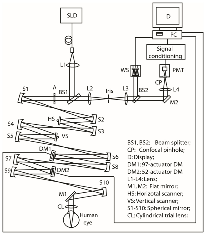
The experimental AOSLO system.
2.2 The high speed AO system
The AO system consists of a high speed custom Shack-Hartman wavefront sensor, the DM1, and the DM2. DM1 has 97 actuators with maximum stroke up to 30 micrometers and Bandwidth > 750 Hz, and DM2 has 52 actuators with maximum stroke up to 50 micrometers and Bandwidth > 200 Hz. The use of 2 DMs allowed us to compensate the optical aberration of the system with one DM and correct the human eye’s wave aberration with the other.
The custom high-speed Shack-Hartmann wavefront sensor
An ideal wavefront sensor for high speed AO correction should possess the following properties. 1) High speed that ensures accurate measurement of high frequency temporal fluctuation of the wave aberration. This requires that the wavefront sensor camera must have a fast frame rate and high quantum efficiency. 2) An adequate spatial sampling density that allows for precise estimation of the spatial variation of the wave aberration. This demands that the wavefront sensor must have a large number of micro-lenslets or subapertures across the wavefront. 3) A large dynamic range that can measure large aberrations. This requires that the subaperture must be sufficiently large. 4) High sensitivity that can detect subtle wave aberration over a subaperture (the local wavefront tilt over a lenslet). This dictates a large number of pixels within the area on the imagining chip subtending to a lenslet. Among these parameters, the large subaperture for a large dynamic range inevitably reduces the total number of the lenslets across the beam and results in decreased spatial sampling density. The large number of pixels corresponding to one subaperture for high measurement sensitivity raises the total number of pixels of the wavefront sensor camera, consequently leading to reduced frame rate and decreased AO speed. More importantly, in an AO retinal imaging system, the photons for wavefront detection may be obtained either by splitting a small amount the imaging light [6, 36] or by use of a beacon light [7, 35]. Due to the safety limitation on light exposure to the eye, the wavefront sensor operates under a very stringent light budget. The low light level dictates long integration time thereby decreasing wavefront detection speed. Our wavefront sensor has been designed with the consideration of all these restrictions and trade-offs.
We selected a complementary metal-oxide semiconductor (CMOS) sensor based camera (MicroVista®-NIR, Intevac Inc., Santa Clara, CA), which has been optimized with enhanced near-infrared response. The quantum efficiency can be up to or greater than 50% around 840 nm, which is a spectral region of the light sources employed by many ophthalmic imaging modalities. In contrast, the quantum efficiency of a charge-coupled device (CCD) imaging chip (typically employed by a Shack-Hartmann wavefront sensor) is about 10% only. The CMOS camera has 1280 X 1024 pixels with a pixel size of 10.8 μm X 10.8 μm. It has different region of interest (ROI) settings that increase frame rate by reduce pixelation. This function allows us to decide an optimal ROI with adequate pixels and fast frame rate that ensures high speed, high spatial sampling density, large dynamic range, and high sensitivity. We adopted a lenslet array with 0.3 mm X 0.3 mm lenslet pitch and 7.6 mm focal length (0300-7.6-S, Adaptive Optics Associates, Cambridge, MA). In the AOSLO, the beam diameter on the CMOS sensor is 4.8 mm, which covers 16 lenslets across the beam and is sampled by 193 sampling subapertures. Each lenslet (subaperture) covers 27 X 27 pixels. With a ROI including 512 X 512 pixels on the CMOS sensor, the camera can operate at a frames rate of 110 frames/second under the AOSLO imaging condition.
High-Speed AO strategy: dual-thread parallel wavefront detection and compensation
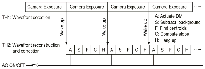
In a pilot study [38] we demonstrated a dual-thread AO control strategy. Although this algorithm enabled a loop frequency up to 110 Hz, it has a drawback; the DM actuates during the wavefront sensor exposure. In our AOSLO, the wavefront reconstruction process (including wavefront sensor background subtraction, centroid calculation, and DM command derivation) takes ~6 ms. Thus, the DM actuation occurs just in the middle of a 10 ms exposure period (which corresponds to the 100 Hz loop frequency) and the accuracy of wavefront detection is inevitably impacted. The AO must take more loops to minimize the aberration, resulting in decreased AO bandwidth. In this study, we revised the algorithm (Fig. 2) to let the DM actuate at the beginning of the next exposure period thereby minimizing the impact of the DM actuation on wavefront detection.
Fig. 2.
High speed AO wavefront detection and correction. Wavefront compensation is carried out when AO is turned on. When AO is off, the deformable mirror is disabled thus the system functions as a wavefront sensor.
The influence function was obtained by measuring the wavefront response on the wavefront sensor induced by each individual actuator [39, 40]. The system interaction matrix was formed by arranging the deflections of all subapertures over the pupil generated by each individual actuator in a column. Since there are 193 subapertures and each subaperture estimates both x and y deflections, for DM1 (with 97 actuators), the dimensions of influence matrix are 386 X 97. For DM2 (with 97 actuators), the dimensions of influence matrix are 386 X 52. Wavefront reconstruction strategy described by Li et al [39] was adopted to calculate the commands for actuating the DMs.
The AO software was written with an option check for AO ON/Off, as shown in Fig. 2. When AO OFF is checked, the DMs are disabled and there is no wavefront correction. The AO system becomes a high speed wavefront sensor that can be operated at 110Hz.
2.3. Evaluate the high speed wavefront sensor in the AOSLO
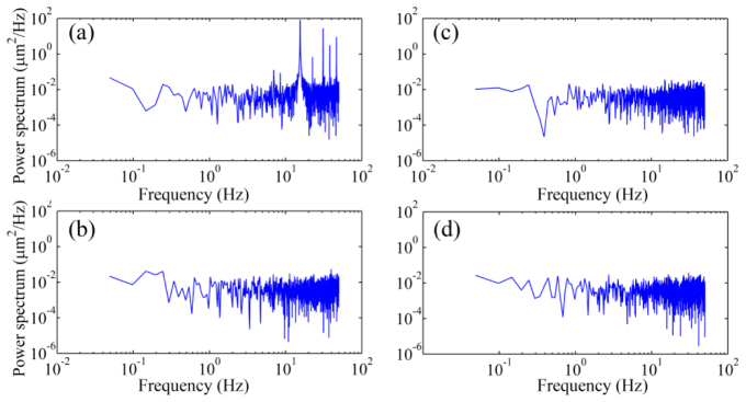
We first assessed the wavefront sensor in the AOSLO using a static model eye. Before the testing, AO was operated to eliminate any aberration existing in the AOSLO optical system and the DM2 was frozen with the shape ensuring the system (statically) diffraction limited. The wavefront of the model eye was measured under 4 conditions. 1) Both horizontal (fast) and vertical (slow) scanners were scanning over a field of 1.2° X 1.2°; 2) both scanners were disabled with the power supply turned off; 3) The fast scanner was scanning over a 1.2° and the slow scanner was disabled with the power supply turned off; 4) the fast scanner was scanning over a 1.2 ° and the slow scanner was powered on with a constant zero voltage (no scanning). Under each condition, the wavefront was recorded over a period of 20 seconds. The power spectrum was calculated through Fourier transform of the time series of the wavefront aberration, as shown in Fig. 3. Frequency components arising at the harmonics of the scanning frequency (7.5 Hz, 15 Hz, 30 Hz, and 45 Hz) are evident in the time series data.
Fig. 3.
The power spectra of the wavefront aberration of a static model eye in the AOSLO measured under different light scanning conditions. (a) Both horizontal (fast) and vertical (slow) scanners were scanning over a field of 1.2° X 1.2°. (b) Both scanners were power off. (c) The horizontal (fast) scanner was scanning over a 1.2° angle and the vertical (slow) scanner was power off. (d) The horizontal (fast) scanner was scanning over a 1.2° angle and the vertical (slow) scanner was power on but applied with 0 volt voltage. The artificial frequency component of 15 Hz and its harmonic components are apparent when the vertical scanner was running.
2.4. Assess the dynamics of wavefront aberration of the human eye in the AOSLO
The purpose of this experiment is to validate the high speed wavefront sensor under the AOSLO imaging condition. Five subjects between 20 and 49 years of age in good chorioretinal health were recruited. All participants underwent assessment of best-corrected visual acuity (BCVA) and measurement of refractive error using an automated refractor. All eyes had the BCVA of 20/20 or better and the refractive errors were within 0 to −2.0 D.
The wavefront aberration was measured under 2 different conditions, with paralyzed and unparalyzed accommodation (natural viewing). All subjects underwent test with paralyzed accommodation fixating on the left end of the scanning light line on the retina which was focused at infinity [19]. The pupil of the subject was dilated with 1.0% tropicamide and 2.5% phenylephrine hydrochloride. Three subjects whose age between 20 and 35 years were tested with unparalyzed accommodation, measurements were made while the subject accommodated on a fixation target at the distance 250 mm, i.e., 4 D [21]. The target was coupled into the system by a pellicle beam splitter just before the entrance pupil of the system. The subject’s head was aligned and stabilized with the use of a head mount with a chinrest.
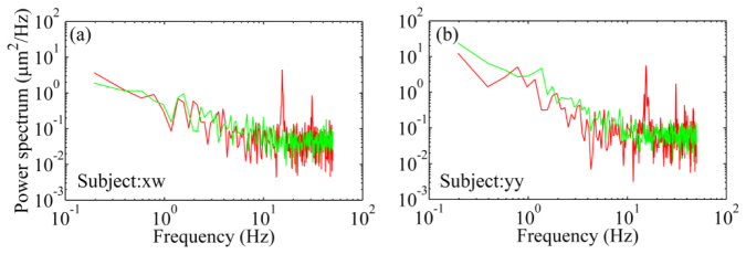
The artificial 15 Hz and its harmonics were also found in the power spectra in the human eye (Fig. 4). To avoid these artificial components, we disabled the vertical scanner and let the fast scanner scan only, i.e., only a line of light (rather than a raster) scanning across the retina during the wavefront measurement. Under this condition, we accordingly reduced the power of the light incident on the cornea to 30 μW, about 1/8 of the maximum permissible exposure level of the ANSI standards [41]. The pellicle beam splitter BS2 was replaced with a silver coated flat mirror which directs all the light from the eye to the wavefront sensor. For each condition, ten series of the time courses of the RMS wavefront aberration were acquired with a period of 10 seconds at 100 Hz. A 5-second span without blinking was picked up from the recorded time series for spectral analysis.
Fig. 4.
The power spectra of the human eyes’ wavefront aberration. The red lines are power spectra obtained with both horizontal (fast) and vertical (slow) scanners scanning over a field of 1.2° X 1.2°. The artificial frequency component of 15 Hz and its harmonic components are apparent. The green lines represent power spectra obtained with the fast scanner scanning (over a 1.2° angle) only and the slow scanner was power on but applied consistently with 0 V. There are no artificial frequency components arising at the harmonics of the slow scanner.
2.5 Evaluate the high-speed AO performance
The purposes of this test are two-fold: to validate the new control algorithm and to estimate the benefit of the high speed AO for compensation of ocular wave aberration. Five eyes of the 5 subjects who were recruited for assessing the dynamics of the ocular wavefront aberration were imaged with the AOSLO using the high speed AO. The imaging was conducted with paralyzed accommodation. The subject was asked to fixate on the top-left corner of the scanning light raster (appearing as a dark red square) on the retina, i.e., the infinity. Because both scanners were used, the pellicle beam splitter BS2 was used to pick up the light reflected from the eye for wavefront measurement. The power incident on the cornea is 500 μW, well below the maximum permissible exposure level of the ANSI standards [41].
We first validated the new AO control algorithm in the living human eye. To evaluate the performance, we recorded and compared the RMS of the ocular wave aberrations before and after AO correction with AO operated at 100 Hz and 20 Hz. For the 20 Hz AO, the wavefront sensor was also operated at 100 Hz, but the DM commands were calculated by averaging 5 successive measurements of the aberration, i.e., the wavefront was measured at 100 Hz but the correction was done at 20 Hz. This is equivalent to the classical closed-loop control sequence. The AO performance was estimated by power rejection ratio, ωa(f)/ωb(f), where ωa(f) and ωb(f) are the Fourier transform of the RMS wavefront aberrations after and before AO correction [23]. For each condition, five series of the time courses of the RMS wavefront aberration were acquired with a period of 10 seconds and a 5-second span without blinking was picked up for spectral analysis.
Most experiments were conducted using the DM with 97 actuators. During the testing, the DM with 52 actuators was first operated to minimize the system aberration and then was ‘frozen’ to maintain a static shape. The high speed control algorithm was also tested with the DM with 52 actuators. In this case, the DM-97 was operated to make a diffraction limited static AOSLO system.
2.6 Assess the improvement in the quality of the retinal images
The ultimate goal of high speed AO is to improve in vivo retinal imaging. We thus attempted to directly compare the quality of the retinal images taken with the AO at 100 Hz and at 20 Hz. The images were acquired in 2 subjects with dilated pupil and paralyzed accommodation with 1.0% tropicamide and 2.5% phenylephrine hydrochloride. During imaging, the subjects were asked to fixate at a high contrast target located at the far point. Images were acquired at 4 degrees away from the foveal center nasally along the primary horizontal retinal meridian. The reason for selecting this area is that AOSLO starts to reveal rods (in addition to cones) from this eccentricity. Thus, images acquired from this area may provide an assessment of the improvement of cone and rod imaging. Before recording the video, the subject was asked to maintain a consistent interval between blinking. We first watched the in vivo retinal images without AO correction, when we observed that the subject had fixated at the target and the retinal image brightness became stable (without significant variation due to tear film change or blinking), we turned on AO correction and recorded the video over a period of 20 seconds. The video included a short period (3-5 seconds) before AO was turned on. Videos were recorded in pair. The 20 Hz AO video was recorded first and then the 100 Hz AO images were acquired. Between recordings, the subject was asked to blink and relax eye quickly. Subjects were not told which AO was used and unable to distinguish two AO conditions. Three pairs of videos under different AO correction were acquired for each subject.
AOSLO image distortions caused by nonlinearities in the resonant scanner and by eye movements were eliminated by customized software. Registered images were averaged to enhance signal-to-noise ratio. AOSLO image pixel size was computed from an image of a precisely calibrated dot grid placed at the retinal plane of a model eye.
To assess the improvement of the retinal image quality, we compared the visibility of rods in the retinal images, the power spectra and gross histograms of successive images acquired within a certain time period. AOSLO videos of 5-second span (75 frames) without blinking and significant eye motion induced distortion taken under different AO conditions were picked up for comparison. After images registration, image subsections (256 X 256 pixels over a field of view of 0.53 degree) of exactly the same portions of retina containing the same photoreceptors were selected and cropped from the registered successive video frames. Average retinal image power spectra were computed from the cropped 5-second videos through Fourier transform. The power spectra of the retinal image taken under different AO conditions were compared. Finally, histograms of 75 successive retinal images within the selected 5-second video taken with 100 Hz AO and 20 Hz AO were computed.
3. Results
3.1 The power spectra of the noise floor of the AOSLO wavefront detection
Figure 3 shows the power spectra of the residual wave aberration of the AOSLO measured with a static model eye under different light scanning conditions. The residual RMS wave aberration was less than 0.04 μm after AO correction for the wavefront aberration of the AOSLO system including the model eye. The artificial frequency component due to the scanning nature at 15 Hz and related harmonic components at 7.5 Hz, 30 Hz, and 45 Hz are apparent. These artifacts were also found in the power spectra in the human eye, as shown in Fig. 4.
3.2 Dynamics of the human eye wavefront aberration
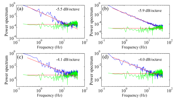
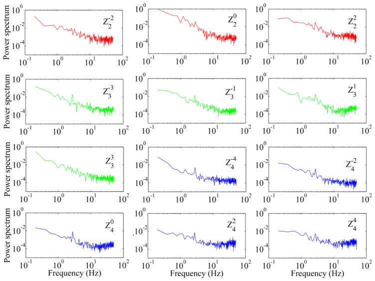
The temporal frequencies of the wavefront aberration measured in 5 subjects under different fixation conditions range from 10 to 42 Hz with an average of 30 Hz. As shown in Fig. 5, when subjects fixated on the target at 250 mm distance, i.e., with near accommodation, the power spectra falls with a slope approximately of 5.3 dB/octave, whereas when subjects fixated on the target at infinity the power spectra falls with a slope approximately of 4 dB/octave. The power falling rate was assessed by the slope of the least-square fitting line to the power spectra data. All subjects demonstrated a similar trend of the power spectra under the same testing condition. The spectra are similar for all the Zernike orders (Fig. 6).
Fig. 5.
The power spectra of the wavefront aberration of the human eye under different fixation conditions. (a) & (b) were obtained from 2 subjects when they fixated on a target at 25 cm distance, i.e. accommodation of 4.0 D. (c) & (d) were obtained from 2 subjects when they fixated on the left end of the line formed by the scanner over the retina, i.e., the infinity. The green curves are the power spectra of the static mode eye. Each spectral plot is an average of the spectra of 5 series of time courses of the RMS wavefront aberration over 5 seconds. In each panel, the power spectra of the human eye and the model eye were normalized with the maximum spectral component of the human eye’s wavefront aberration, which varied person to person. Thus, the model eye’s spectral curves are at different levels that are related to the maximum spectral component of the single individual.
Fig. 6.
The power spectra of Zernike modes of the wavefront aberration. The aberration was measured with paralyzed accommodation from one subject’s eye over a 6 mm pupil. The red, green, and blue curves are spectra of the 2nd, 3rd, and 4th order of the Zernike modes, respectively. The subject fixated on the left end of scanning line (the infinity). The power spectra are an average of the spectra of 10 series of time courses of the RMS wavefront aberration over 5 seconds. All the spectra of the Zernike modes were normalized with the maximum spectrum of the defocus ().
3.3 The performance of the high speed AO
With the closed-loop frequency of 100 Hz, AO can reduce the RMS wave aberration to less than 0.05 μm in most eyes, meeting the Maréchal criterion, which indicates that when the RMS wave aberration is less than 1/14 wavelength the imaging is diffraction limited, as shown in Fig. 7. Compared to AO operated at 20 Hz, AO operated at 100 Hz is faster to reach the diffraction limited state. Exemplary AOSLO video acquired with AO correction at 100 Hz is shown in Fig. 8. The robust performance of the new AO control algorithm is evidenced by the significantly improved resolution, brightness and contrast. The power spectra of the wavefront aberration were compressed after AO correction, shown in Fig. 9. The power rejection ratios of the Fourier components of the aberrations within 0 – 50 Hz are less than 1, indicating that all frequency components were suppressed by AO compensation.
Fig. 7.
AO corrects wavefront aberration with the closed-loop frequency of 100 Hz and 20 Hz. (a) The subject’s eye was with a nature pupil and accommodation. (b) The pupil of the same subject was dilated with 1.0% tropicamide and 2.5% phenylephrine hydrochloride. The accommodation was paralyzed. The subject fixated on the upper-left corner of the light scanning rater, i.e., the infinity. For the 20 Hz AO, the wavefront aberration was measured at 100 Hz but the correction was conducted at 20 Hz. DM1 (Hi-Speed DM97-15, ALPAO SAS, France) was used to correct the wave aberration during the image acquisition.
Fig. 8.
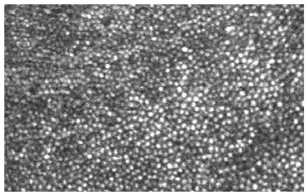
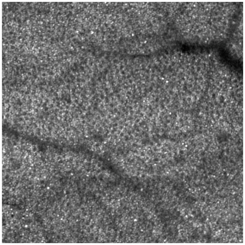
AOSLO video with AO correction for wavefront aberration at 100 Hz (Visualization 1 (6.8MB, AVI) ). At the beginning of this video, AO is not turned on and cone photoreceptors are invisible. AO starts at the 5th frame. The brightness, contrast, and resolution were significantly improved. Contiguous cone mosaic is clearly resolved. The image was taken at the nasal retina 0.5 degree away from the foveal center. The frame size is of 0.8 degree X 0.5 degree or approximately 240 μm X 150 μm. The image distortion caused by nonlinear scanning of the resonant scanner was corrected but the distortion caused by eye movements remained. DM1 (Hi-Speed DM97-15, ALPAO SAS, France) was used to correct the wave aberration during the image acquisition.
Fig. 9.
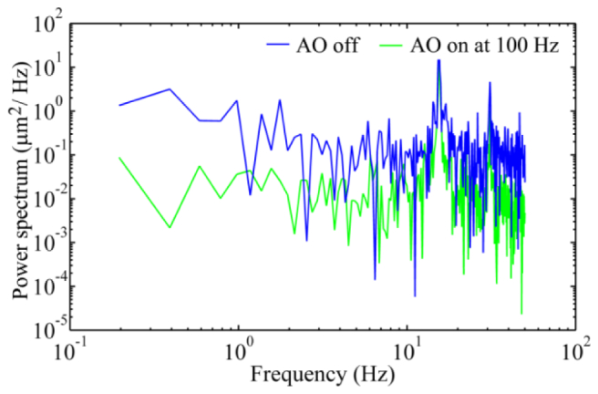
AO corrects wavefront aberration with the closed-loop frequency of 100 Hz. The blue line represents the power spectra of the wave aberration before AO correction, whereas the green line is the power spectra of the residual wave aberration after AO correction. DM1 (Hi-Speed DM97-15, ALPAO SAS, France) was used to correct the wave aberration during the image acquisition.
Figure 10 illustrates the quantitative assessment of high speed AO benefit. Over 0.2 – 30 Hz, the power rejection ratios obtained with the AO operated at a loop frequency of 100 Hz are clearly smaller than those obtained with the AO operated at 20 Hz. The power rejection ratios achieved by the AO working at 20 Hz are greater than 1 beyond 7 Hz (at many frequency points), indicating an inefficiency of low speed correction, whereas for AO operated at 100 Hz, no power rejection ratio is greater than 1 over 0.2- 50 Hz.
Fig. 10.
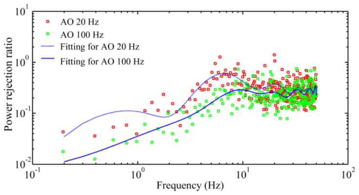
Comparison of AO compensation of wavefront aberration with 20Hz and 100 Hz closed-loop frequency. The power rejection ratios (red and green dots) are average values of 5 subjects. The trend lines are least square fitting. For the 20 Hz AO, the wavefront aberration was measured at 100 Hz. DM1 (Hi-Speed DM97-15, ALPAO SAS, France) was used to correct the wave aberration during the image acquisition.
3.4 The improvement in the quality of the retinal images
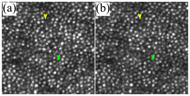
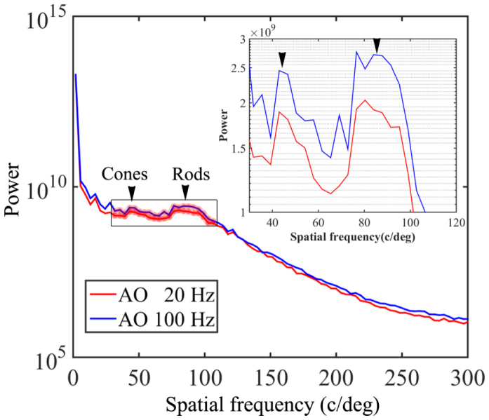
The comparison between the images acquired with AO operated at 100 Hz and 20 Hz indicates that high speed AO correction has brought improved image quality. Figure 11 shows that the image taken with high speed AO presents increase brightness and enhanced visibility of rod photoreceptors (indicated by the yellow and green arrowheads). Detailed power spectral analysis revealed an overall improvement of the power spectra of the retina images, as shown in Fig. 12. Over the spectral range of cone and photoreceptor distribution, the retinal image power spectra were increase by 18% to 56% with the 100 Hz AO correction of the eye’s aberrations. The improvement in retinal image quality is also demonstrated by the increased number of bright pixels in the overall histogram of 75 successive retinal images within a 5-second video taken from one subject with the 100 Hz AO (Fig. 13).
Fig. 11.
AOSLO images taken with 100 Hz AO (a) and 20 Hz AO (b). The images were acquired at 3 degrees eccentricity nasally along the primary horizontal retinal meridian. The size of these images is 256 pixels subtending a field of view of 0.53 degree. Each image is a registered set of 75 AO-corrected frames and has been corrected for distortions due to eye movements. The average center-to-center spacing of cones around the yellow arrowhead is 7.50 μm (measured within a 50 μm X 50 μm area). The average center-to-center spacing of rods is about 3.1 μm (measured from the resolved visible rods). Yellow and green arrowheads indicate improved visibility of rod photoreceptors in the image taken with the high speed 100 Hz AO. DM1 (Hi-Speed DM97-15, ALPAO SAS, France) was used to correct the wave aberration during the image acquisition.
Fig. 12.
Radial power spectra of the retinal images taken with 100 Hz AO and 20 Hz AO correction. Each plot is an average of the radial power spectra of 75 successive retinal images within a 5-second video from one subject. The images were acquired at 4 degrees eccentricity nasally along the primary horizontal retinal meridian. The averaged retina images are shown in Fig. 11. Black arrowheads point to the peaks corresponding to cones (~41 cycles/degree) and rod (~90 cycles/degree). The inset is the magnified spectral region indicated by the box over which the improvement of power spectra by the 100 Hz AO correction is 18-56%. DM1 (Hi-Speed DM97-15, ALPAO SAS, France) was used to correct the wave aberration during the image acquisition.
Fig. 13.
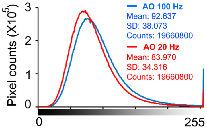
Histograms of 75 successive retinal images within a 5-second video taken from one subject with 100 Hz AO and 20 Hz AO correction. The images were acquired at 4 degrees eccentricity nasally along the primary horizontal retinal meridian. DM1 (Hi-Speed DM97-15, ALPAO SAS, France) was used to correct the wave aberration during the image acquisition.
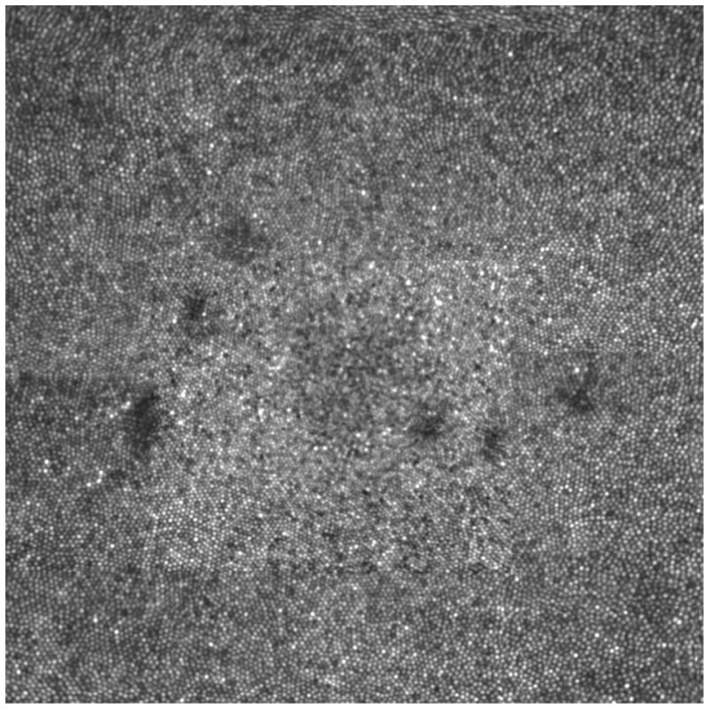
Figure 14 is the retinal image taken from a subject in normal retinal health, showing well resolved and contiguous foveal cone photoreceptor mosaic. Figure 15 shows well resolved cone and rod photoreceptor mosaic.
Fig. 14.
The AOSLO image taken in the fovea of a human subject (woman, 49 years old) with healthy retina. The image size is of 2°, or approximately 600 μm on a side. The image is a montage of a series of individual images taken across fovea with a 1.2° field of view. All individual images are a registered set of 20 AO-corrected frames and have been corrected for distortions due to eye movements. DM1 (Hi-Speed DM97-15, ALPAO SAS, France) was used to correct the wave aberration during the image acquisition.
Fig. 15.
The AOSLO image showing cone and rod photoreceptors taken in the retina of human subject (woman, 60 year old) with healthy retina. The image size is of 2°, or approximately 600 μm on a side. It is a montage of a series of individual small images taken with a 1.2° field of view. All small images are a registered set of 20 AO-corrected frames and have been corrected for distortions due to eye movements . The image was taken along the equator of the retina nasally about 9° away from the foveal center, revealing that cones (the large spots with dark annulus) are surrounded by rods (small spots). The AOSLO DM1 (Hi-Speed DM97-15, ALPAO SAS, France) was used to correct the wave aberration during the image acquisition.
4. Discussion
The discovery of high frequency temporal variation of the ocular wave aberration in the human eye [19, 21] dictates the necessity of high speed AO correction for high resolution retinal imaging. In this study, we investigated the technical approaches to achieving the AO speed, including a custom high speed wavefront sensor and a parallel control strategy.
A high speed wavefront sensor is critical for achieving high speed AO correction. The high speed must be achieved with adequate spatial sampling density, dynamic range, and sensitivity. Although a few wavefront sensors have been reported [19–21] or claimed to have high frame rate (e.g., HASO 4 FIRST, pco.edge, OCAM2, and Zyla, made by Alpao SAS, France, the WFS20-14AR from Thorlabs, Inc, NJ), to our best knowledge, an AO system for retinal imaging with a closed-loop frequency > 90 Hz has not been reported after the pioneer work of Diaz-Santana et al [19]. We should note that the wavefront sensor reported by Diaz-Santana et al was made on a 128 X 128 pixels sensor and had only 21 subapertures over the pupil, which is insufficient for correcting the wavefront with high spatial frequency aberrations. Statistical assessment from different populations indicates that the human eye may have high order wavefront aberrations up to the 10th order of Zernike modes, corresponding to 63 modes in total (excluding piston, tip, and tilt) [42–44]. This requires at least 63 subaperatures for measuring the wavefront across the pupil [45]. For a practical AO system, the wavefront sensor must have more lenslets than this minimum number. In our study, we designed wavefront sensor with 193 subapertures over the sensor area including 512 X 512 pixels. This is important because the DMs used in our experiment AOSLO, the mirao 52-e has 52 actuators and the DM97-15 has 97 actuators, requiring more spatial sampling points.
We confirmed the existence of high frequency fluctuations in the wavefront aberration in the human eye with the fast wavefront sensor under the AOSLO imaging condition (Figs. 5 and 6). When subjects looked at infinity, the power spectra of the wave aberration featured a frequency slop of 4 dB per octave close to 30 Hz (on average), whereas the power spectra measured with near accommodation decreased with a slope of 5.5 dB per octave. These results agree well with previous studies [19–21] and further substantiating the necessity of high speed AO.
The high frequency fluctuation of the wave aberration demands a high sampling rate for wavefront measurement and compensation. According to the sampling theorem, the sampling rate of the wavefront sensor must be at least 2 times greater than that of the highest frequency of the aberration [22]. With the custom high speed wavefront sensor, we were able to implement an improved dual-thread AO control strategy and achieved a loop frequency up to 110 Hz. Compared to AO operating at 20 Hz, AO operating at 100 Hz has been demonstrated to make the AOSLO reach diffraction limited state within shorter time (Fig. 7). High speed AO yielded clearly improved power rejection ratio of the ocular wave aberration over the frequency range 0.2 – 30 Hz than the low speed AO (Fig. 10). Retinal images acquired with the high speed AO showing improved visibility of the fine rod cell structure and increase power spectra (Figs. 11 and 12). With high speed AO, the foveal center cones and rods in the parafovea, which have been difficult to resolve, have been revealed in the eyes in good chorioretinal health (Figs. 11, 13, and 14).
The speed (110 Hz) of the AO system achieved in this study represents a critical yet still a preliminary step to compensate the wave aberration with temporal frequency up to 30 Hz. In addition to the sampling rate (i.e., the loop frequency), the bandwidth (of the error transfer function) of an AO system is also limited by the phase delay induced by the wavefront detection and calculation of the DM commands as well as the DM actuation, in particular, by the intrinsic 1-frame delay of the wavefront correction (DM action) to the wavefront detection. To achieve an error rejection bandwidth of 30 Hz, assuming that the AO operates with a classical discrete integrator control law and the control system has no other latency else than the wavefront detection delay and the response time of the mirror is negligible, the loop frequency should be about 3 (ideally 5) to 10 times of the wave aberration bandwidth, i.e., 90 to 300 Hz [15, 16, 22]. Thus, our work just met the minimum requirement only. Further improvement of the AO speed with faster wavefront sensing and more robust control algorithm is needed.
Indeed, low-speed AO systems, even the quasi-static AO systems as demonstrated in early years [1, 5], have provided decent correction and resolution. This is due to the fact that the power spectra of the ocular wave aberration concentrate in the low frequency region. To a certain extent, we might be content to the current AO speed, but the proved existence of high frequency wave aberration rationalizes the needs of high speed AO. Furthermore, many applications, such as measuring the speed of the retinal blood or studying individual photoreceptor function, require that the retinal imaging maintaining consistent quality with well-corrected aberrations over time [46–50]. In clinical imaging, retinal images are often recorded continuously over time, demanding rapid correction after the fixation moved.
Our study was based upon the classical AO regime using a wavefront sensor. A notable development trend in current AO retinal imaging is the sensorless correction that based upon optimization of the retinal images brightness [51–55]. This mechanism is dictated by the imaging frame rate and requires long time (~10 seconds) to correct the wave aberration. In essence, it corrects for low frequency variation of the ocular wavefront.
There are important limitations in our study. First, the accuracy of wavefront detection in the dual-thread AO control algorithm is intrinsically affected by the DM actuation [38]. To mitigate this drawback, we have improved the algorithm to let the DM actuate at the beginning of the next exposure period to minimize the impact, but this results in a 1-frame delay in correction. Although the 100 Hz AO performed better than the 20 Hz AO system, the wavefront correction is not as efficient as that of a pure 100 Hz system. This effect may have been reflected in Fig. 7, although the 100 Hz AO is 5 times faster than the 20 Hz system, the time for the AOSLO reaching diffraction limit was not reduced accordingly. This problem can be solved by use of a camera with an improved timing mechanism that can halt the exposure a while (for example, 0.5 second) when it receives the message from the wavefront reconstruction and correction thread and then resume the exposure. By this way we can avoid the DM auction impact on the wavefront detection. The camera used in this study unfortunately does not have this function. Thus we are just limited by a practical obstacle, not a principle problem. Second, while we have demonstrated the improvement in optical performance of the AOSLO as well as in the quality of retinal images afforded by the high speed AO, we have not quantitatively evaluated this improvement in a large number of subjects with various eye conditions. It is possible that the improvement in retinal image quality obtained by high speed AO correction may vary widely among individuals due to different amounts of temporal fluctuation in their ocular wavefront. Furthermore, we must recognize that retinal image quality is also affected by many other factors in addition to the ocular wavefront aberration, such as the clarity of the lens and the vitreous, the uniformity of the team film, and the eye motion, etc. For example, even in an emmetropic eye of a young subject, the image brightness can be significantly varying within a very short time period due to tear film changing. Despite all these adverse conditions, in general, we may expect the improvement in retinal image quality with the high speed AO, especially in those subjects who have high frequency temporal instability in ocular wave aberrations. With the fast wavefront sensor, we may first assess the temporal spectral range of the individual subject’s ocular wavefront before imaging thereby deciding the optimal AO speed.
5. Conclusion
We have developed a high speed AO system that can compensate high frequency ocular wave aberration in the living human eye. The AO system was implemented in an experimental AOSLO and demonstrated improved compensation of the wavefront aberration up to 30 Hz.
Supplementary Material
Acknowledgments
This project was supported by funding from NIH 5R21EY021903, NIH 2R44EY019197, NIH R01EY024378, and institutional support from Research to Prevent Blindness, EyeSight Foundation of Alabama, Buck Trust of Alabama, and NIH P30 EY003039. Yongxin Yu is supported by a visiting scholarship fund from Tianjin University and the University of Alabama at Birmingham International Exchange Scholar Program. We thank Jinyu Wang for developing part of the program.
References and links
- 1.Liang J., Williams D. R., Miller D. T., “Supernormal vision and high-resolution retinal imaging through adaptive optics,” J. Opt. Soc. Am. A 14(11), 2884–2892 (1997). 10.1364/JOSAA.14.002884 [DOI] [PubMed] [Google Scholar]
- 2.Hofer H., Chen L., Yoon G. Y., Singer B., Yamauchi Y., Williams D. R., “Improvement in retinal image quality with dynamic correction of the eye’s aberrations,” Opt. Express 8(11), 631–643 (2001). 10.1364/OE.8.000631 [DOI] [PubMed] [Google Scholar]
- 3.Doble N., Yoon G., Chen L., Bierden P., Singer B., Olivier S., Williams D. R., “Use of a microelectromechanical mirror for adaptive optics in the human eye,” Opt. Lett. 27(17), 1537–1539 (2002). 10.1364/OL.27.001537 [DOI] [PubMed] [Google Scholar]
- 4.Rha J., Jonnal R. S., Thorn K. E., Qu J., Zhang Y., Miller D. T., “Adaptive optics flood-illumination camera for high speed retinal imaging,” Opt. Express 14(10), 4552–4569 (2006). 10.1364/OE.14.004552 [DOI] [PubMed] [Google Scholar]
- 5.Roorda A., Romero-Borja F., Donnelly W., III, Queener H., Hebert T., Campbell M., “Adaptive optics scanning laser ophthalmoscopy,” Opt. Express 10(9), 405–412 (2002). 10.1364/OE.10.000405 [DOI] [PubMed] [Google Scholar]
- 6.Zhang Y., Poonja S., Roorda A., “MEMS-based adaptive optics scanning laser ophthalmoscopy,” Opt. Lett. 31(9), 1268–1270 (2006). 10.1364/OL.31.001268 [DOI] [PubMed] [Google Scholar]
- 7.Burns S. A., Tumbar R., Elsner A. E., Ferguson D., Hammer D. X., “Large-field-of-view, modular, stabilized, adaptive-optics-based scanning laser ophthalmoscope,” J. Opt. Soc. Am. A 24(5), 1313–1326 (2007). 10.1364/JOSAA.24.001313 [DOI] [PMC free article] [PubMed] [Google Scholar]
- 8.Hermann B., Fernández E. J., Unterhuber A., Sattmann H., Fercher A. F., Drexler W., Prieto P. M., Artal P., “Adaptive-optics ultrahigh-resolution optical coherence tomography,” Opt. Lett. 29(18), 2142–2144 (2004). 10.1364/OL.29.002142 [DOI] [PubMed] [Google Scholar]
- 9.Zawadzki R. J., Jones S. M., Olivier S. S., Zhao M., Bower B. A., Izatt J. A., Choi S., Laut S., Werner J. S., “Adaptive-optics optical coherence tomography for high-resolution and high-speed 3D retinal in vivo imaging,” Opt. Express 13(21), 8532–8546 (2005). 10.1364/OPEX.13.008532 [DOI] [PMC free article] [PubMed] [Google Scholar]
- 10.Zhang Y., Cense B., Rha J., Jonnal R. S., Gao W., Zawadzki R. J., Werner J. S., Jones S., Olivier S., Miller D. T., “High-speed volumetric imaging of cone photoreceptors with adaptive optics spectral-domain optical coherence tomography,” Opt. Express 14(10), 4380–4394 (2006). 10.1364/OE.14.004380 [DOI] [PMC free article] [PubMed] [Google Scholar]
- 11.Zawadzki R. J., Jones S. M., Pilli S., Balderas-Mata S., Kim D. Y., Olivier S. S., Werner J. S., “Integrated adaptive optics optical coherence tomography and adaptive optics scanning laser ophthalmoscope system for simultaneous cellular resolution in vivo retinal imaging,” Biomed. Opt. Express 2(6), 1674–1686 (2011). 10.1364/BOE.2.001674 [DOI] [PMC free article] [PubMed] [Google Scholar]
- 12.Babcock H. W., “The possibility of compensating astronomical seeing,” Publ. Astron. Soc. Pac. 65, 229–236 (1953). 10.1086/126606 [DOI] [Google Scholar]
- 13.Chen L., “Control algorithms,” in Adaptive Optics for Vision Science Principles, Practices, Design, and Applications, Porter J., Queener H., Lin J., Thorn K., Awwal A., eds. (John Wiley & Sons, 2006), pp. 119–137. [Google Scholar]
- 14.Madec P. Y., “Control techniques,” in Adaptive Optics in Astronomy, Roddier F., eds. (Cambridge University Press, 2004), pp. 131–154. [Google Scholar]
- 15.Greenwood D. P., “Bandwidth specification for adaptive optics systems,” J. Opt. Soc. Am. A 67(3), 390–393 (1977). 10.1364/JOSA.67.000390 [DOI] [Google Scholar]
- 16.Greenwood D. P., Fried D. L., “Power spectra requirements for wave-front-compensative systems,” J. Opt. Soc. Am. A 66(3), 193–206 (1976). 10.1364/JOSA.66.000193 [DOI] [Google Scholar]
- 17.Hardy J. W., Adaptive Optics for Astronomical Telescopes (Oxford University Press, 1998). [Google Scholar]
- 18.Hofer H., Artal P., Singer B., Aragón J. L., Williams D. R., “Dynamics of the eye’s wave aberration,” J. Opt. Soc. Am. A 18(3), 497–506 (2001). 10.1364/JOSAA.18.000497 [DOI] [PubMed] [Google Scholar]
- 19.Diaz-Santana L., Torti C., Munro I., Gasson P., Dainty C., “Benefit of higher closed-loop bandwidths in ocular adaptive optics,” Opt. Express 11(20), 2597–2605 (2003). 10.1364/OE.11.002597 [DOI] [PubMed] [Google Scholar]
- 20.Nirmaier T., Pudasaini G., Bille J., “Very fast wave-front measurements at the human eye with a custom CMOS-based Hartmann-Shack sensor,” Opt. Express 11(21), 2704–2716 (2003). 10.1364/OE.11.002704 [DOI] [PubMed] [Google Scholar]
- 21.Mira-Agudelo A., Lundström L., Artal P., “Temporal dynamics of ocular aberrations: monocular vs binocular vision,” Ophthalmic Physiol. Opt. 29(3), 256–263 (2009). 10.1111/j.1475-1313.2009.00655.x [DOI] [PubMed] [Google Scholar]
- 22.Fadali S. M., Visioli A., Digital Control Engineering: Analysis and Design (Academic Press, 2009). [Google Scholar]
- 23.Zhang Y., Rha J., Jonnal R., Miller D., “Adaptive optics parallel spectral domain optical coherence tomography for imaging the living retina,” Opt. Express 13(12), 4792–4811 (2005). 10.1364/OPEX.13.004792 [DOI] [PubMed] [Google Scholar]
- 24.Gray D. C., Merigan W., Wolfing J. I., Gee B. P., Porter J., Dubra A., Twietmeyer T. H., Ahamd K., Tumbar R., Reinholz F., Williams D. R., “In vivo fluorescence imaging of primate retinal ganglion cells and retinal pigment epithelial cells,” Opt. Express 14(16), 7144–7158 (2006). 10.1364/OE.14.007144 [DOI] [PubMed] [Google Scholar]
- 25.Chen D. C., Jones S. M., Silva D. A., Olivier S. S., “High-resolution adaptive optics scanning laser ophthalmoscope with dual deformable mirrors,” J. Opt. Soc. Am. A 24(5), 1305–1312 (2007). 10.1364/JOSAA.24.001305 [DOI] [PubMed] [Google Scholar]
- 26.Jonnal R. S., Rha J., Zhang Y., Cense B., Gao W., Miller D. T., “In vivo functional imaging of human cone photoreceptors,” Opt. Express 15(24), 16141–16160 (2007). 10.1364/OE.15.016141 [DOI] [PMC free article] [PubMed] [Google Scholar]
- 27.Zawadzki R. J., Choi S. S., Jones S. M., Oliver S. S., Werner J. S., “Adaptive optics-optical coherence tomography: optimizing visualization of microscopic retinal structures in three dimensions,” J. Opt. Soc. Am. A 24(5), 1373–1383 (2007). 10.1364/JOSAA.24.001373 [DOI] [PMC free article] [PubMed] [Google Scholar]
- 28.Fernández E. J., Hermann B., Považay B., Unterhuber A., Sattmann H., Hofer B., Ahnelt P. K., Drexler W., “Ultrahigh resolution optical coherence tomography and pancorrection for cellular imaging of the living human retina,” Opt. Express 16(15), 11083–11094 (2008). 10.1364/OE.16.011083 [DOI] [PubMed] [Google Scholar]
- 29.Pircher M., Zawadzki R. J., Evans J. W., Werner J. S., Hitzenberger C. K., “Simultaneous imaging of human cone mosaic with adaptive optics enhanced scanning laser ophthalmoscopy and high-speed transversal scanning optical coherence tomography,” Opt. Lett. 33(1), 22–24 (2008). 10.1364/OL.33.000022 [DOI] [PMC free article] [PubMed] [Google Scholar]
- 30.Zawadzki R. J., Cense B., Zhang Y., Choi S. S., Miller D. T., Werner J. S., “Ultrahigh-resolution optical coherence tomography with monochromatic and chromatic aberration correction,” Opt. Express 16(11), 8126–8143 (2008). 10.1364/OE.16.008126 [DOI] [PMC free article] [PubMed] [Google Scholar]
- 31.Zou W., Burns S. A., “High-accuracy wavefront control for retinal imaging with Adaptive-Influence-Matrix Adaptive Optics,” Opt. Express 17(22), 20167–20177 (2009). 10.1364/OE.17.020167 [DOI] [PMC free article] [PubMed] [Google Scholar]
- 32.Pircher M., Götzinger E., Sattmann H., Leitgeb R. A., Hitzenberger C. K., “In vivo investigation of human cone photoreceptors with SLO/OCT in combination with 3D motion correction on a cellular level,” Opt. Express 18(13), 13935–13944 (2010). 10.1364/OE.18.013935 [DOI] [PMC free article] [PubMed] [Google Scholar]
- 33.Zou W., Qi X., Huang G., Burns S. A., “Improving wavefront boundary condition for in vivo high resolution adaptive optics ophthalmic imaging,” Biomed. Opt. Express 2(12), 3309–3320 (2011). 10.1364/BOE.2.003309 [DOI] [PMC free article] [PubMed] [Google Scholar]
- 34.Zou W., Qi X., Burns S. A., “Woofer-tweeter adaptive optics scanning laser ophthalmoscopic imaging based on Lagrange-multiplier damped least-squares algorithm,” Biomed. Opt. Express 2(7), 1986–2004 (2011). 10.1364/BOE.2.001986 [DOI] [PMC free article] [PubMed] [Google Scholar]
- 35.Dubra A., Sulai Y., “Reflective afocal broadband adaptive optics scanning ophthalmoscope,” Biomed. Opt. Express 2(6), 1757–1768 (2011). 10.1364/BOE.2.001757 [DOI] [PMC free article] [PubMed] [Google Scholar]
- 36.Merino D., Duncan J. L., Tiruveedhula P., Roorda A., “Observation of cone and rod photoreceptors in normal subjects and patients using a new generation adaptive optics scanning laser ophthalmoscope,” Biomed. Opt. Express 2(8), 2189–2201 (2011). 10.1364/BOE.2.002189 [DOI] [PMC free article] [PubMed] [Google Scholar]
- 37.Liu Z., Kocaoglu O. P., Miller D. T., “In-the-plane design of an off-axis ophthalmic adaptive optics system using toroidal mirrors,” Biomed. Opt. Express 4(12), 3007–3029 (2013). 10.1364/BOE.4.003007 [DOI] [PMC free article] [PubMed] [Google Scholar]
- 38.Yu Y., Zhang Y., “Dual-thread parallel control strategy for ophthalmic adaptive optics,” Chin. Opt. Lett. 12(12), 121202 (2014). 10.3788/COL201412.121202 [DOI] [PMC free article] [PubMed] [Google Scholar]
- 39.Li K. Y., Mishra S., Tiruveedhula P., Roorda A., “Comparison of control algorithms for a MEMS-based adaptive optics scanning laser ophthalmoscope,” Proc. Am. Control Conf. 2009, 3848–3853 (2009). [DOI] [PMC free article] [PubMed] [Google Scholar]
- 40.Meadway A., Girkin C. A., Zhang Y., “A dual-modal retinal imaging system with adaptive optics,” Opt. Express 21(24), 29792–29807 (2013). 10.1364/OE.21.029792 [DOI] [PMC free article] [PubMed] [Google Scholar]
- 41.Delori F. C., Webb R. H., Sliney D. H., American National Standards Institute , “Maximum permissible exposures for ocular safety (ANSI 2000), with emphasis on ophthalmic devices,” J. Opt. Soc. Am. A 24(5), 1250–1265 (2007). 10.1364/JOSAA.24.001250 [DOI] [PubMed] [Google Scholar]
- 42.Liang J., Grimm B., Goelz S., Bille J. F., “Objective measurement of wave aberrations of the human eye with the use of a Hartmann-Shack wave-front sensor,” J. Opt. Soc. Am. A 11(7), 1949–1957 (1994). 10.1364/JOSAA.11.001949 [DOI] [PubMed] [Google Scholar]
- 43.Porter J., Guirao A., Cox I. G., Williams D. R., “Monochromatic aberrations of the human eye in a large population,” J. Opt. Soc. Am. A 18(8), 1793–1803 (2001). 10.1364/JOSAA.18.001793 [DOI] [PubMed] [Google Scholar]
- 44.Thibos L. N., Hong X., Bradley A., Cheng X., “Statistical variation of aberration structure and image quality in a normal population of healthy eyes,” J. Opt. Soc. Am. A 19(12), 2329–2348 (2002). 10.1364/JOSAA.19.002329 [DOI] [PubMed] [Google Scholar]
- 45.Yoon G., “Wavefront sensing and diagnostic uses,” in Adaptive Optics for Vision Science Principles, Practices, Design, and Applications, Porter J., Queener H. M., Lin J. E., Thorn K., Awwal A., eds. (John Wiley & Sons, 2006), pp.63–81. [Google Scholar]
- 46.Vogel C. R., Arathorn D. W., Roorda A., Parker A., “Retinal motion estimation in adaptive optics scanning laser ophthalmoscopy,” Opt. Express 14(2), 487–497 (2006). 10.1364/OPEX.14.000487 [DOI] [PubMed] [Google Scholar]
- 47.Arathorn D. W., Yang Q., Vogel C. R., Zhang Y., Tiruveedhula P., Roorda A., “Retinally stabilized cone-targeted stimulus delivery,” Opt. Express 15(21), 13731–13744 (2007). 10.1364/OE.15.013731 [DOI] [PubMed] [Google Scholar]
- 48.Sincich L. C., Zhang Y., Tiruveedhula P., Horton J. C., Roorda A., “Resolving single cone inputs to visual receptive fields,” Nat. Neurosci. 12(8), 967–969 (2009). 10.1038/nn.2352 [DOI] [PMC free article] [PubMed] [Google Scholar]
- 49.Kocaoglu O. P., Ferguson R. D., Jonnal R. S., Liu Z., Wang Q., Hammer D. X., Miller D. T., “Adaptive optics optical coherence tomography with dynamic retinal tracking,” Biomed. Opt. Express 5(7), 2262–2284 (2014). 10.1364/BOE.5.002262 [DOI] [PMC free article] [PubMed] [Google Scholar]
- 50.Yang Q., Zhang J., Nozato K., Saito K., Williams D. R., Roorda A., Rossi E. A., “Closed-loop optical stabilization and digital image registration in adaptive optics scanning light ophthalmoscopy,” Biomed. Opt. Express 5(9), 3174–3191 (2014). 10.1364/BOE.5.003174 [DOI] [PMC free article] [PubMed] [Google Scholar]
- 51.Hofer H., Sredar N., Queener H., Li C., Porter J., “Wavefront sensorless adaptive optics ophthalmoscopy in the human eye,” Opt. Express 19(15), 14160–14171 (2011). 10.1364/OE.19.014160 [DOI] [PMC free article] [PubMed] [Google Scholar]
- 52.Bonora S., Zawadzki R. J., “Wavefront sensorless modal deformable mirror correction in adaptive optics: optical coherence tomography,” Opt. Lett. 38(22), 4801–4804 (2013). 10.1364/OL.38.004801 [DOI] [PubMed] [Google Scholar]
- 53.Jian Y., Xu J., Gradowski M. A., Bonora S., Zawadzki R. J., Sarunic M. V., “Wavefront sensorless adaptive optics optical coherence tomography for in vivo retinal imaging in mice,” Biomed. Opt. Express 5(2), 547–559 (2014). 10.1364/BOE.5.000547 [DOI] [PMC free article] [PubMed] [Google Scholar]
- 54.Bonora S., Zawadzki R. J., “Wavefront sensorless modal deformable mirror correction in adaptive optics: optical coherence tomography,” Opt. Lett. 38 (22), 4801-4804 (2014). [DOI] [PubMed] [Google Scholar]
- 55.Wong K. S. K., Jian Y., Cua M., Bonora S., Zawadzki R. J., Sarunic M. V., “In vivo imaging of human photoreceptor mosaic with wavefront sensorless adaptive optics optical coherence tomography,” Biomed. Opt. Express 6(2), 580–590 (2015). 10.1364/BOE.6.000580 [DOI] [PMC free article] [PubMed] [Google Scholar]
Associated Data
This section collects any data citations, data availability statements, or supplementary materials included in this article.


