Abstract
A single human red blood cell was optically stretched along two counter-propagating fiber-optic Bessel-like beams in an integrated lab-on-a-chip structure. The beam enabled highly localized stretching of RBC, and it induced a nonlinear mechanical deformation to finally reach an irreversible columnar shape that has not been reported. We characterized and systematically quantified this optically induced mechanical deformation by the geometrical aspect ratio of stretched RBC and the irreversible stretching time. The proposed RBC mechanism can realize a versatile and compact opto-mechanical platform for optical diagnosis of biological substances in the single cell level.
OCIS codes: (350.4855) Optical tweezers or optical manipulation, (060.2310) Fiber optics, (060.2370) Fiber optics sensors, (130.3990) Micro-optical devices
1. Introduction
Since Ashkin experimentally demonstrated optical trapping and transportation of dielectric particles, optical manipulation of microscopic living objects has been one of the prominent research fields in biomedical photonics [1]. Dielectric bead trapping technique was readily applied to biological cell trapping [2], taking advantages of tiny optical forces on the order of 10−12 N and utilizing flexible capability to locate the cells in specific positions. Recently, opto-mechanical deformation of biological cell is being highly cited to correlate opto-mechanical properties with biological healthiness in the single cell level [3–7]. For example, Hénon et al. investigated the elastic shear modulus of the human red blood cell (RBC: erythrocyte) membrane [3], by attaching two dielectric beads side by side on the surface of RBC. These beads were optically trapped to provide a net shear force on RBC. Using a similar scheme, Dao et al. [4] analyzed a deformation of RBC beyond the elastic regime and discussed the dependence of the viscoelastic shear modulus upon the strain of RBC. Guck et al. [5–7] further developed the single RBC stretching using two counter-propagating Gaussian beams without attaching dielectric beads, and estimated the stretching stress on RBC as a function of the laser power. However, their Gaussian beam dimension was larger than that of the RBC and only the spatially averaged elastic properties of RBC were attainable, and the localized deformation of RBC beyond the elastic regime has not been discussed in detail.
Optical trapping also brought the development of various beam shaping techniques such as vortex beams [8], lattice beams [9], Bessel beams [10, 11], and Airy beams [12] to explore light assisted manipulation of dielectric particles. The authors’ group recently demonstrated all fiber Bessel-beam generator (AFBG), which showed a high potential in versatile optical manipulation of particle especially in the microscopic environment, due to its flexible deployment capability and compact form factor [13, 14]. AFBGs have realized Bessel beam’s general characteristics in a concatenated optical fiber structure such that they provided non-diffracting and self-healing characteristics over a macroscopic distance. Despite its unique potential in highly localized optical manipulation of dielectric particles, AFBGs have not been applied to optical stretchers and detailed interaction of Bessel beam with RBC has not been reported in detail, where the central beam diameter is smaller than the size of RBC, in contrast to prior Gaussian beam stretching experiments.
In this study, we proposed and experimentally demonstrated an advanced optical stretching platform for a single RBC, using two counter-propagating all-fiber Bessel beams integrated in a compact opto-fluidic lab-on-a-chip system, for the first time to the best knowledge of the authors. Utilizing a highly confined central beam and a long non-diffracting length of the fiber optic Bessel-like beam, nonlinear viscoelastic properties of RBC were investigated in a highly localized manner, which have not been possible in prior researches based on Gaussian beams. The proposed configuration enabled systematic investigation on the nonlinear viscoelastic behavior of RBC with a low optical power, which can be further used as a bio-photonic signature to assess the status of RBC healthiness.
2. The Bessel beam stretcher
2.1 Configuration
Experimental configuration of our study is schematically shown in Fig. 1. Two nearly identical AFBGs were mounted on a polydimethylsiloxane (PDMS) chamber with a saline water flow controller, where RBCs were carried through. Two laser diode (LD) output fibers (HI 1060 FLEX) were fusion-spliced to AFBGs and the RBC trapping and stretching processes were recorded using an inverted microscope and a CCD camera. We chose the wavelength of LD at λ = 980 nm to maintain a low level of light absorption both in the water and in the RBC, minimizing detrimental thermal effects [15]. The coherence length of the LD was also chosen sufficiently short (< 100 μm) so as to inhibit the beam interference in the counter propagating scheme. By using a high precision micro-pump, the flow rate of saline water was accurately controlled for stable delivery of RBCs. All the RBC stretching processes were recorded in situ, by a CCD camera with a frame speed of ~20/s, with a magnification of 20~100 times.
Fig. 1.
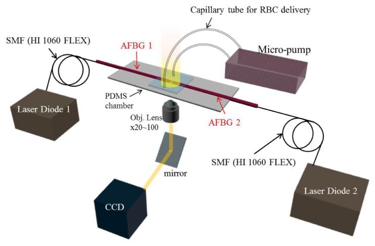
The schematic diagram of experimental setup for the proposed fiber optic stretcher in lab-on-a chip: all fiber Bessel-like beam generator (AFBG), laser diode (λ = 980 nm) with a pig tailed single mode fiber (HI 1060 FLEX), polydimethylsiloxane (PDMS) chamber, and micro-pump connected to capillary tube for sample (RBC) delivery.
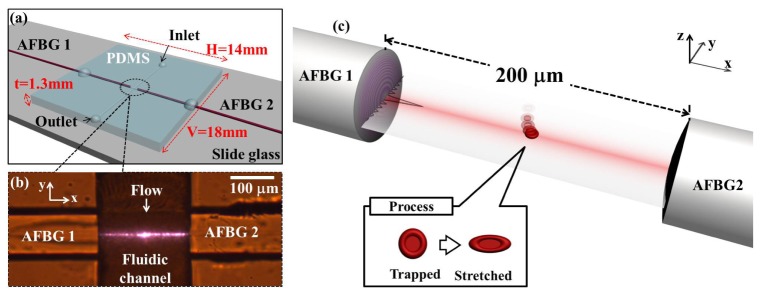
The schematic diagram of the RBC stretching zone is further magnified in Fig. 2(a). Two counter propagating beams from AFBGs were arranged perpendicular to the fluid flow direction in a microfluidic PDMS channel. In order to integrate AFBG into the channel, we used photoresist (SU-8 2000, Microchem) and single mode fiber as a mold, and a soft lithography method was applied to develop the fiber holder and the fluid channel [16]. An actual photograph of the fabricated fiber-integrated opto-fluidic channel and two AFBGs is shown in Fig. 2(b). Using this fiber optic fluidic platform, single RBC stretching experiment was carried out as schematically illustrated in Fig. 2(c). Note that the RBC stretching was observed along the x-direction, and balancing between the optical trapping force and the fluid drag force was maintained along the y-direction.
Fig. 2.
(a) Schematic diagram of the proposed fiber optic lab-on-a-chip to optically stretch single RBC. RBCs in a saline solution were fed into the channel from inlet to outlet through capillary tubes. (b) Actual photograph of the microfluidic channel and counter-propagating beams from two AFBGs at the wavelength of 980 nm. (c) Schematic diagram of optical stretching of RBC in the proposed system.
RBCs were prepared by a finger-tip method from healthy donors. 0.9% Saline solution was used for balancing osmotic concentration which prevents hemolysis [17]. RBC has a biconcave shape with an average diameter dRBC is 6.6 ± 0.6 μm, and thickness tRBC is 1.7 ± 0.8 μm [5]. The refractive index of discotic RBCs nRBC is 1.378 ± 0.005 [18], and that of the saline solution nwater is 1.334. RBCs contained in a droplet of blood (20 μl) and the 1 ml of saline water was delivered into a PDMS chamber by a microfluidic pump. Optical stretching of RBC was achieved in following two steps: (i) Optical trapping of RBC by balancing between the fluid drag force and the optical gradient force of the Bessel-like beam, along the y direction (the liquid flow direction) in Fig. 2(b). (ii) Optical stretching of RBC along the x-direction (the beam direction) by the two counter-propagating Bessel-like beams in Fig. 2(c).
Our Bessel-like beams were propagating about 62.5 μm above the bottom of PDMS channel. If the liquid flow was too slow, most of RBC’s gradually sank to the bottom to result in a poor optical trapping efficiency. In an excessively fast flow, the drag force on RBC was much larger than the optical gradient force to result in a poor trapping efficiency. At an optimal flow rate of 100~170 μm/s, we achieved the highest optical trapping efficiency with the Bessel-like beam power of ~40 mW. By measuring the drag force on a RBC [19], the equilibrium gradient force (Fgrad) acting on the RBC was estimated to be 3.55~6.03 pN at an optimal flow rate of 100~170 μm/s. The force due to viscous drag Fdrag is:
| (1) |
where η is the liquid viscosity, rRBC is the radius of RBC approximated as a circular disk shape, v is the liquid velocity. We used η = 1.002 × 10⁻³ Ns/m, rRBC = 3.3 μm, s = 0.566 [19].
2.2 All fiber Bessel beam generator characteristics
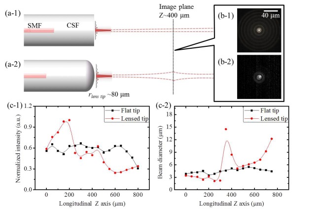
An advanced type of AFBG was fabricated by concatenating single mode fiber (HI 1060 FLEX, core diameter: 3.4 μm) and coreless silica fiber (CSF) with an optimized length of 1600 μm to support a desired spatial multi-mode interference (MMI) pattern simulating the Bessel beam profile. In comparison to prior AFBGs [14] that used a fiberized lens on the CSF facet as shown in Fig. 3(a-2), the advanced one in this study did not mount any lens but the CSF end face remained as a flat surface as in Fig. 3(a-1). We measured and compared the beam characteristics of these two types of AFBGs and the results are summarized in Fig. 3(b)-3(c). Here the curvature of fiberized lens in the prior AFBG type was 0.0125/μm (or equivalently a radius of 80 μm) as indicated in Fig. 3(a-2). We measured the transverse beam intensity profiles using a CCD camera at the propagation distance of 400 μm, and the results are shown in Fig. 3(b-1) and 3(b-2). It was noted that the advanced AFBG showed a clear distinction between the central beam and the first ring, which would provide a higher spatial resolution in RBC stretching than prior AFBG. Variations in the longitudinal intensity and the beam diameter are summarized in Fig. 3(c-1) and 3(c-2), respectively. The advanced “Flat-tip” provided a non-diffracting length of ~700 μm and a central beam diameter of ~4 μm. These correspond to ~30% increase in the non-diffracting length and ~40% reduction in the central beam diameter in comparison to our previous report [14], which confirmed that the AFBG could provide a highly localized transfer of the light momentum to RBC. We took the same measurements in the water using a micro mirror, and the results were nearly identical to Fig. 3.
Fig. 3.
The schematic diagram of two types of AFBG and their beams propagation in the air: (a-1) Flat tip type (advanced one) and (a-2) Lensed tip type (prior one). The cross section images of the beam from AFBGs with the flat tip (b-1) and the lensed tip (b-2) taken by a CCD camera at the propagation distance of 400 μm from fiber tip. The longitudinal (c-1) and transverse (c-2) intensity profiles of beams from AFBGs with flat tip (black) and lensed tip (red).
Next, the beam from the advanced AFBG was compared with a conventional Gaussian-like beam from a SMF (HI 1060, FLEX) and the results are shown in Fig. 4. In contrast to the Gaussian beam in Fig. 4(a-1), our Bessel-like beam showed a transverse intensity profile with the characteristic concentric ring distribution in Fig. 4(a-2). The central beam diameter of our Bessel-like beam was ~4 μm (FWHM) at the axial position of 100 μm in the air, about 4 times smaller than that of the Gaussian beam, as shown in Fig. 4(a-3). This position was selectively chosen because most of the trapping and stretching occurred near this position. Using a beam profiler, we measured that the central beam carried about 15% of the total optical power of the Bessel-like beam. Experimentally we found that trapping and stretching of RBC were mainly caused by the central beam of the Bessel-like beam, therefore we isolated the central beam from the side lobe rings by spatially filtering, and further characterized the central beam variation along the axial direction. In Fig. 4(b) and 4(c), our Bessel-like beam maintained the axial uniformity both in its central beam intensity and the beam diameter. Transverse beam profiles and longitudinal intensity profiles in the water did not change significantly in comparison to those in air, which have been confirmed numerically and experimentally in our previously published papers [13, 14].
Fig. 4.
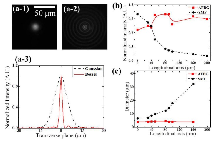
The transverse intensity profiles of (a-1) Gaussian beam from a conventional single mode fiber and (a-2) Bessel-like beam from proposed fiber device taken by a CCD camera at the propagation distance of 100 μm from fiber tip in the air. (a-3) transverse line profiles of Gaussian and Bessel-like beam from (a-1) and (a-2). (b) the intensity and (c) the diameter of the central peak of Bessel-like beam along the propagation axis in the air.
3. Optical stretching of Bessel beam
3.1 Optical stretching force
RBC optical stretching mechanism by two counter propagating Gaussian beams has been analyzed in detail by J. Guck [5,6]. He theoretically calculated the stretching force based on ray optics and also showed that the results were consistent to the Lorenz-Mie scattering theory when the light wavelength is much smaller than the sample (Dsample >>λ). In our study, this condition is also satisfied with RBC diameter, dRBC, of 6~7 μm, and the laser wavelength of 0.98 μm. However, the main differences between our Bessel-like beam and prior Gaussian beam in the RBC stretching are: 1) non-diffracting nature of our Bessel-like beam to provide a much longer interaction length, 2) highly localized central beam with the diameter of 4 μm. These two differences resulted in a very different stretching capability and stretching dynamics in the Bessel-like beams.
In the following, we review the optical stretching mechanism [5,6] and we will discuss the experimental results of Bessel beam stretching and subsequent data analysis followed by a phenomenological interpretations. When a single laser beam propagates through a cell suspended in water, light momentum change occurs twice at the boundary between the water and the cell due to the difference of refractive indices. By taking time derivative of momentum, stretching force acting on front surface (Ffront) and back surface (Fback) of the cell can be defined as below [5, 6]:
| (2a) |
| (2b) |
P is the input optical power (W), r is the reflection coefficient at the surface of the RBC (RRBC = 0.002 [6]), nwater and nRBC is refractive index of saline water and RBC, respectively. Qfront and Qback are the momentum transfer factors at the front and the back surface, respectively. By the momentum conservation, the direction of Qfront is opposite to that of Qback. Therefore, the total stretching force acting on each surface is equal to the half of |Ffront| + |Fback|. Even though a single laser can stretch the cell, the cell tends to be transported along the beam propagation direction due to the imbalance between Ffront and Fback [5]. This imbalanced force is scattering force acting on object whose direction is identical to beam propagation direction. If two counter-propagating beams are incident on a RBC, there is no net scattering force because of the mechanical equilibrium, and the total stretching force exerted on each surface is given as below [6]:
| (3) |
where Ftot is the total stretching force acting on RBC by dual beams.
3.2 Surface stress of dual Bessel beams
For accurate estimation of the optical stretching force, Guck et al. defined the surface stress, σ, (the force per unit area) along the surface where the light enters and leaves the RBC [5]. Surface stress induced by dual Bessel-beams can be derived from the stretching force by the following equations. Here we only considered the central peak of the Bessel-like beam because the side robe rings did not contributed to optical stretching directly.
| (4a) |
| (4b) |
| (4c) |
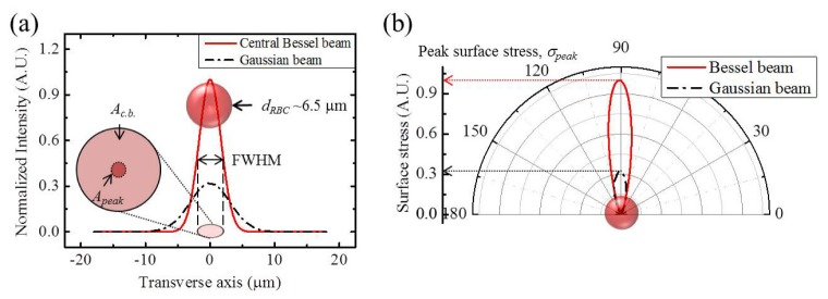
Ac.b. is the total FWHM beam area of the central beam among Bessel-like pattern from the AFBG acting on RBC surface. The bi-concave RBC acts as a lens and focuses the rays. Therefore, momentum transfer of entire central beam was considered for estimating stretching force [6] even though the FWHM of the central beam was larger than tRBC. See Fig. 4(a-2), 4(a-3) and Fig. 5(a). Apeak is the central peak beam area within 1 μm2 as shown in the inset image of Fig. 5(a). F, Pc.b., Ic.b., Q, and, c are the optical stretching force, the central beam power and intensity of Bessel beam, the momentum transfer factor, and light velocity in vacuum, respectively. Consistent to prior analyses [5,6], we defined Ftot as the total stretching force acting on RBC by dual Bessel beams and σpeak as the maximum surface stress within 1 μm2 area of the peak beam as Eqs. (4b) and (4c).
Fig. 5.
(a) The normalized intensity of the central beam of our AFBG (red solid) and a Gaussian beam used in prior reports [5,6] (black dash dot line) at the 100 mW beams. Inset image is the typical size of Red Blood Cell. Ac.b. is the total FWHM beam area of the central beam. Apeak is the central peak beam area within 1 μm2. dRBC is the diameter of red blood cell. (b) The polar profiles of total surface stress on one surface of single RBC by Gaussian and Bessel-like beam.
Note that only the central beam in our AFBG was contributing to the effective RBC stretching in our experiments and the central beam was well fitted to a Gaussian intensity distribution as the red solid lines in Fig. 5(a). This distribution stayed in a non-diffracting manner as shown in Fig. 3 and 4, and the central beam’s FWHM area was assumed to be maintained over the entire RBC width. We estimated the surface stress from the measured central beam power of AFBG as shown in Fig. 4(b) and 4(c). Since our Bessel-like beam had the central beam diameter of ~4 μm, we were able to observe a highly localized optical momentum transfer on the RBC surface (dRBC: 6~7 μm). This is a significant contrast to prior Gaussian beam experiments, whose diameter was about 7~8 μm covering the whole surface of RBC [5, 6]. Assuming that identical output power was incident on the RBC, our Bessel-like beam resulted in a σpeak almost three times larger than those achievable by Gaussian beams, as shown in Fig. 5(b). Therefore, our dual Bessel-like beams enabled a large nonlinear deformation of RBC at a significantly lower optical power than previous Gaussian beam studies.
3.3 Reversible and irreversible stretching by Bessel beam
We experimentally observed very distinctive two optical deformation regimes of RBC as a function of the Bessel-like beam power. When Pc.b., was in the range of 0~38 mW with the fluid flow rate of 100~170 μm/s, neither trapping nor stretching were observed. When the power increased to 39~57mW, both optical trapping and stretching of a single RBC occurred and the RBC resumed the original shape when the laser was turned off, as in Fig. 6(a). We classified this regime as the “Reversible stretching phase”. When the power further reached a range of 57~97 mW, the RBC showed a unique columnar deformation and did not resume its original shape even when the laser was turned-off as shown in Fig. 6(b). This columnar shape was maintained without further mechanical relaxation. We classified this range as the “Irreversible stretching phase.” 5 samples were measured for classifying each typical stretching range.
Fig. 6.
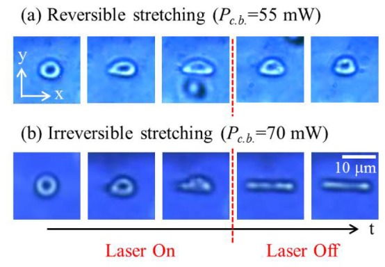
Sequential images of optically stretched single RBC by two counter propagating AFBGs in two distinctive deformation regions: (a) At Pc.b. = 55 mW, reversible stretching where the stretched RBC recovered its original shape and (b) at Pc.b. = 70 mW, irreversible stretching where the stretched RBC maintained its deformation after the laser was turned off. At each range, 5 samples were measured and characterized.
In addition to these characteristic phases, we could observe “Splitting phase” at the optical power over 97 mW, where the single RBC was split to separate structures. Those split structures were not predictable and changed in an irregular manner. Therefore, we pursued systematic investigations by focusing only on “Reversible stretching phase” and “Irreversible stretching phase”.
Using Eqs. (4a), (4b), and (4c), we estimated the optical stretching force and surface stress delivered on RBC by dual Bessel-like beams. In Table 1, we summarized characteristics of two optical stretching phases for the single RBC optical stretching.
Table 1. Total stretching force and peak surface stress as a function of central beam power shinining on RBC stretched by two counter-propagating fiber optic Bessel-like beams.
| Phase | Pc.b. (mW) | Ftot (pN) | σpeak (pN/μm2) |
|---|---|---|---|
| Reversible Stretching | 39~57 | 10~16 | 1.5~2.2 |
| Irreversible Stretching | 57~97 | 16~27 | 2.2~3.7 |
Here, we used the following parameters: nwater = 1.334, Qfront = −3.8×10⁻², Qback = 4.9×10⁻², and c = 3.0×10⁸ m/s. Qfront had a negative value and it means direction stretching force acting on RBC surface is opposite to the beam propagation direction. It was previously reported that the deformation of RBCs became nonlinear beyond the linear elasticity regime when σpeak exceeded 2.2 pN/μm2 [6]. The range of σpeak for the irreversible phase in our experiments was 2.2~3.7 pN, which is consistent to this prior nonlinear stretching range.
It is also noteworthy that the highly localized Bessel-like beams resulted in unique RBC deformations as shown in Fig. 7, which have never been reported previously. When a part of RBC was stretched off-center such that the beam did not pass through the center of RBC, only the part of RBC irradiated by the dual Bessel-like beams (solid white arrows) stretched along the beam direction. In contrast, the rest of RBC was not deformed and remained almost stress-free to result in a unique shape composed of an optically stretched part and the pristine rest. Using the flow rate of saline water, the deformation shape was further controlled. For a fixed optical powder of the Bessel-like beams, RBC deformed to a snail shape (Fig. 7(a)) at the flow rate of 150 μm/s and a hat shape (Fig. 7(b)) at the follow rate of 138 μm/s. Because this stretch was not symmetric and significantly affected by the flow rate of liquid, it was difficult to evaluate accurate strains only by the optical surface stress, and the authors are investigating this unique deformation and will report these phenomena in a separate article.
Fig. 7.
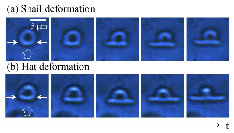
Time series images of specially deformed single RBC by flow (dot arrow) and dual Bessel beams (solid arrows: Ftot ~23 pN) (see Visualization 1 (1.6MB, MP4) ): (a) Snail shape deformation and (b) Hat shape deformation at the flow rate of 150 μm/s and 138 μm/s, respectively.
4. The characterization of Columnar deformations
4.1 Geometrical aspect ratio of deformed RBC
We introduced an “aspect ratio R of RBC optical stretching” as a physical parameter to quantify the two distinctive optical stretching phases in this study. In Eq. (5), R is defined as the ratio of λx to λy, which are the deformation ratios of a single deformed RBC along x, and y axes, respectively.
| (5) |
lx’ and lx are the initial and final lengths of stretched RBC along the x axis. ly’ and ly are the initial and final lengths of stretched RBC along the y axis. These parameters are shown in Fig. 8(a) and 8(b). See Fig. 2 for the axial directions and note that the x-axis is parallel to the beam propagation direction. We measured 20 incidents of RBC optical stretching to understand the relationship between the optical power and the aspect ratio R in the RBC deformation. The experimental measurements are summarized in Fig. 8, where each point was averaged for 5 measurements.
Fig. 8.
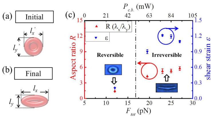
(a) Initial status (before deformation) and (b) final status (deformation completion) of a single RBC image and its 2 dimensional length along x and y axes (c) Aspect ratio R of the deformed RBC plotted as a function of total stretching force Ftot induced by the dual Bessel-like beams. Insets are typical deformed RBC images at two distinctive stretching phases: Reversible phase (left) and Irreversible phases (right). 20 samples were taken by CCD for analysis. The error bars are standard deviations.
We estimated the shear strain ε for R and added the results to the right y axis of the Fig. 8(c). Please note that the shear strain ε in Fig. 8(c) is the essential data for theoretical modelling of irreversible stretching time tI.S. in the next section 4.2 ‘irreversible stretching time’. Note that in the reversible stretching phase, the aspect ratio R remained less than 1.5, and in the irreversible stretching phase the RBCs were deformed to a columnar shape with a high aspect ratio R over 4.2, which is about three times larger than that of reversible stretching phase. We found an abrupt increase in R at the cut off between the reversible and irreversible stretching phases. The cut off was estimated to be between 12 and 18 pN according to the measured data. This large contrast in the aspect ratio was mainly attributed to the highly localized Bessel-like beams from our AFBGs, which enabled non-diffracting stretching of RBC along the beam axial direction on a highly localized spot. The aspect ratio of stretched RBCs was found to serve as a representative physical parameter to distinguish whether the optical stretching is linear viscoelastic (reversible) or nonlinear viscoelastic/plasticity (irreversible) deformation. The aspect ratio could vary depending on the cellular types and their health conditions, and further application of this unique characterization method for optical stretching based on Bessel-like beams to other bio dielectric particles are being pursued by the authors.
4.2 Irreversible stretching time
Using a CCD camera mounted on a microscope, we were able to record the progress of RBC optical stretching as a function of time so that we could quantify how long it took for a RBC to be deformed in an irreversible manner. We further quantified the irreversible RBC deformation phase by introducing another physical parameter ‘irreversible stretching time, tI.S.’, the total elapsed time for a RBC to be deformed to a columnar shape in the irreversible stretching phase. Note that tI.S. was measured from the moment of the equilibrium optical trapping till the onset of the permanent columnar deformation for each RBC as shown in Fig. 9(a). The aspect ratio ‘R’ in the previous section represents the magnitude of spatial deformation induced by the Bessel-like beam. In contrast, the irreversible stretching time ‘tI.S.’ represents how fast the Bessel-like beam stretches the RBC to a final columnar shape. Therefore, these physical parameters ‘R’ and ‘tI.S.’ can represent the RBC optical stretching process using Bessel-like beams in spatial and temporal dimensions.
Fig. 9.
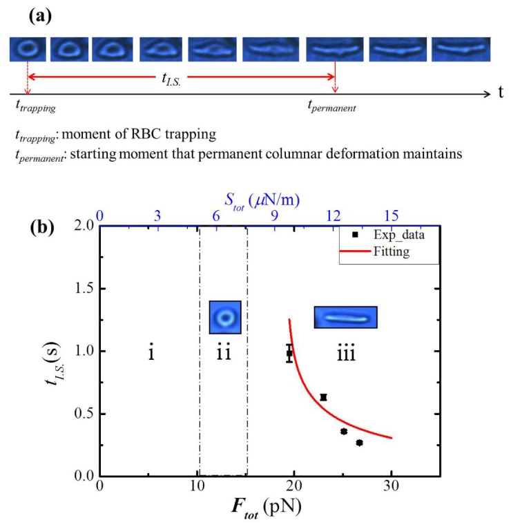
(a) Sequential images of a irreversibly stretched single RBC (see Visualization 1 (1.6MB, MP4) ) and definition of irreversible stretching time tI.S. (b) tI.S. as a function of Ftot and Stot. Distinctive deformation region of optical stretching as a function of Ftot acting on RBC (i: Neither trapping nor stretching, ii: Trapping & Reversible stretching, iii: Irreversible stretching) The number of measured samples is 12 (Each data includes 3 measured RBC samples). Fit curve was derived in Eq. (7) and was approximated to the experimental data (red-line).
The irreversible stretching time tI.S. was measured as a function of Ftot and the results are summarized in in Fig. 9(b). Here the measurement error of tI.S. entailed the sample to sample variations and the frame rate of the CCD camera. In Fig. 9(b), we overlaid the followings: region ‘i’ where neither trapping nor stretching observed, region ‘ii’ where trapping and reversible stretching observed, region ‘iii’ where the irreversible stretching obtained. Our measurements on ‘tI.S.’ were taken only in the irreversible stretching region.
In previous studies, RBC deformation progress has been described in the linear viscoelasticity regime and the cases of applying stress to the cell by micropipette or bead to bead trapping method [3, 4, 18] have been explained in the regime. In viscoelasticity, the strain-stress relation is time-dependent due to the viscosity of water inside RBC membrane, in contrast to instantaneous reaction in phospholipid bilayer following the linear elasticity (Hook’s law) [20]. There are two main deformation mechanisms in the linear viscoelasticity; creep retardation with stress loading, and stress relaxation without stress loading [20, 21]. The former has been described by Kelvin/Voigt model and the latter by Maxwell model [20]. Kelvin/Voigt model has been used to describe RBC deformation, which relates the shear strain ε, shear modulus μRBC and the shear stress S in exponential time dependence as below.
| (6) |
Here, τ*is the retardation time and is defined by the viscosity ηRBC divided by the elastic shear modulus μRBC [20, 21]. In case of elastic deformation, shear strain ε scaled linearly with shear stress S without exponential term in Eq. (6).
In prior RBC deformation studies and literature [3, 4, 20], the strain of RBC were defined along the principal axes (x and y axes) in the rectangular coordinate as the deformation ratio of λx, and λy [20]. We estimated λx, and λy from the real images of deformed RBC taken by a CCD camera. The shear strain ε was defined as below [3, 4, 20].
| (7) |
Here ex, and ey are principal extension (x axis) and contraction (y axis) strain of deformed RBC in large deformation [4, 18, 20]. The membrane of RBC is commonly modelled as an incompressible effective continuum structure [18] and based on this assumption, RBC was assumed to be an in-plane 2 dimensional circle, and shear strain ε and shear stress S (force per unit length) are used as principal parameters to analyze viscoelastic properties of RBCs [4, 18, 20]. We define the shear stress Stot acting on RBC circle as the total stretching force Ftot over RBC thickness tRBC (~2 μm). Thus, the irreversible stretching of RBC can be regarded as an in-plane shear stretching process [20,21] originated from the shear strain of deformation, ε and the optical shear stress, Stot. To reflect our observation that the columnar deformation maintained an aspect ratio R~5 regardless of surfaces stress as shown in Fig. 8 (c), we assumed that the strain ‘ε’ maintained a certain value for various Stot. In our experiments, we empirically obtained a constant averaged strain of ε ~1.1, and we estimated the irreversible stretching time tI.S., when the shear strain ε reached 1.1 as a function of Stot using Eq. (6) as below:
| (8) |
We need Stot larger than 1.1μRBC for valid estimation in Eq. (8). This formula was plotted as a fitting curve in the red line of Fig. 9. In the fitting process, we obtained the physical parameters: μRBC ~ 8.5 μN/m, ηRBC ~2.5 μN·s/m at 25°C, and τ* ~ 0.3. In prior RBC stretching experiments, the shear modulus μRBC was reported to be in the range of 2~20 μN/m [3, 4, 18, 20, 21] and our estimation of μRBC ~8.5 μN/m was consistent to these values. Also, our estimation of the viscosity ηRBC was ~2.5 μN·s/m and this was in the range of 2~6 μN·s/m reported in prior RBC deformation studies [21, 22]. In fact, the strain ε was about ~0.9 for Stot ~9.5 μN/m, while ε ~1.2 for Stot ~12.6 μN/m (Table 2), which inevitably included the measurement errors based on video analysis. Further enhancement of video frame rates and resolution would decrease these errors.
Table 2. The averaged parameters from Sigmoidal fit curve to the shear strain process under different Stot loading.
| Pc.b. (mW) | σtot (pN) | Stot (μN/m) | (s) | (s) | ||
|---|---|---|---|---|---|---|
| 71 | 19.5 | 9.5 | 0.0201 | 1.0580 | 0.2335 | 0.6833 |
| 84 | 23 | 11.5 | 0.0195 | 1.3466 | 0.1379 | 0.4570 |
| 91 | 25 | 12.6 | 0.0192 | 1.3700 | 0.1518 | 0.2170 |
| 97 | 27 | 13.4 | 0.0198 | 1.1541 | 0.1267 | 0.0813 |
In Eq. (8), it is also noteworthy that tI.S. as a function of Stot, is strongly dependent upon μRBC, and we theoretically investigated how our Bessel beam stretcher can differentiate the impacts of various μRBC and the results are summarized in Fig. 10. Here we used our empirical parameters obtained in our measurements, strain ε = 1.1, and viscosity ηRBC = 2.5 μN·s/m.
Fig. 10.
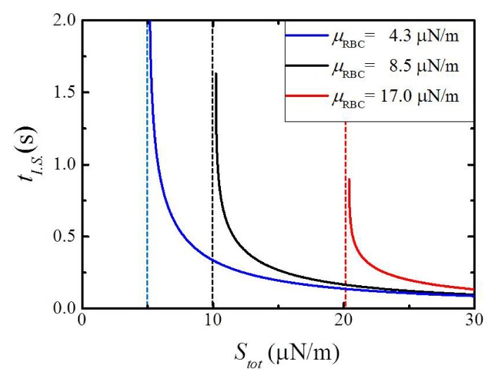
Irreversible stretching time tI.S. as a function of Stot with respect to different shear moduli μRBC; Blue line: 4.3 μN/m, Black line: 8.5 μN/m, and Red line: 17 μN/m (The constraints: strain ε is 1.1, and viscosity ηRBC is 2.5 μN·s/m) Each dot lines are asymptotes at different shear moduli and means the optical surface stress where irreversible stretching occurs.
As shown in Fig. 10, both the slope and the asymptote (dotted vertical line) in the plots of tI.S. as a function of Stot, were highly dependent upon μRBC. Note that each asymptote indicates the optical shear stress where the irreversible RBC deformation initiates. We found a monotonic increase in the asymptote of Stot as a function of μRBC, which strongly indicates that information on μRBC can be systematically extracted from the plots of tI.S. versus Stot in our Bessel beam stretcher. It has been reported that the shear stress μRBC was closely related with the health status of RBC [23, 24], yet prior research required post processes to extract the information. In our Bessel beam stretcher, the health status of a single RBC could be monitored and compared quantitatively in a fast manner close to in situ, by simple measurements of tI.S. as a function of Stot.
4.3 Investigation of impacts on RBC’s elastic shear modulus by alcohol concentration
In prior section, we only estimated shear modulus of RBC from healthy donors in normal saline solutions. In order to investigate the feasibility of our scheme for estimation of RBC healthiness, we further experimentally studied the impacts of alcohol on RBC’s shear modulus. We prepared 4 groups of RBC (100 μl) in different alcohol-saline solution: saline solution (5 ml) mixed with ethyl alcohol (C2H5OH) concentration of 0%, 0.1% (5 μl), 0.5% (25 μl) and 5% (250 μl). RBCs were immersed in these solutions for 30 minutes and they were stretched using our Bessel-like beams to measure the irreversible stretching time tI.S., at the room temperature of 25°C. The numbers of measured cell at 0%, 0.1%, 0.5%, and 5.0% alcohol concentration are 80, 58, 84, and 76, respectively.
Experimental data were plotted in symbol scattered plots in Fig. 11 and they were fitted by theoretical curves using Eq. (8). It was found that there exists a close correlation between the change in tI.S. and the alcohol concentration. Note that the irreversible stretching time tI.S. as a function of Stot gradually was reduced for increasing alcohol concentration. For example, at Stot ~9.5 pN/m, tI.S. decreased from 1.34 to 0.57 s as the ethyl alcohol concentration increased from 0 to 5.0%. It is also noted that when Stot further increased beyond 14 pN/m, the fitted curves for various alcohol concentrations converged with significantly reduced difference in tI.S.. From the fitted curves, we quantitatively estimated the shear modulus μRBC of RBC, which is one of mechanical properties closely related to RBC health status [23]. We could estimate μRBC in 0, 0.1, 0.5, and 5% ethyl alcohol concentration were ~8.5, ~8.2, ~7.5, and 6.4 N/m, respectively. In comparison to μRBC in the saline solution without alcohol, μRBC in the solution with 5% alcohol concentration was reduced by almost 20%. These results imply that ethyl alcohol does modify the RBC membrane to result in noticeable decrease in the elastic shear modulus. The effects of alcohol solution on RBC have been reported by Raman spectroscopy, where the porphyrin breathing mode intensity showed significant decrease by 20% alcohol solution [25]. This report is consistent to our own observations in terms of alcohol effects on RBC, and further attempts to correlate the optical stretching and Raman spectroscopy are being pursued by the authors.
Fig. 11.
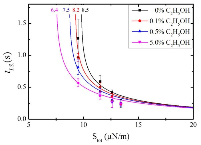
Irreversible stretching time tI.S. as a function of Stot for RBC groups in various alcohol-saline solutions. Experimental data are represented by symbols, which are fitted by theoretical curves in solid lines. RBC (100 μl) was mixed with saline solutions (5 ml) of No alcohol 0% (Black square), 0.1% ethyl alcohol (Red circle), 0.5% ethyl alcohol (Blue triangle), and 5% ethyl alcohol (Magenta nabla). The numbers of measured RBC at 0%, 0.1%, 0.5%, and 5.0% are 80, 58, 84, and 76, respectively. The error bars represent standard deviations. Here we used the constraints strain ε of 1.1, and viscosity ηRBC of 2.5 μN·s/m. The numerical values shown at fitted curves are the shear moduli μRBC (μN/m).
4.4 Time series strain measurement of irreversibly stretched red blood cell: Sigmoidal curve
As we further investigated the kinetics of optical stretching, we found that the behavior of irreversible deformation by Bessel-like beam did not follow the prior Kelvin/Voigt model in Eq. (5). Instead of this model, a Sigmoidal function [26] was found to successfully represent all the experimental data within an acceptable tolerance. Sigmoidal curves have been widely used in pharmacology and toxicology to define the response time of biological cells under a certain medicine dose [26]. The mathematical description of a Sigmoidal curve is shown as below:
| (9) |
Here εi is the initial shear strain of the RBC before stretching, and εf is the final shear strain of irreversibly stretched RBC along in-plane x, and y axes and t0 is the time at the beginning of deformation. And τ* is retardation time in Kelvin/Voigt model, and it is related to the slope of strain over time.
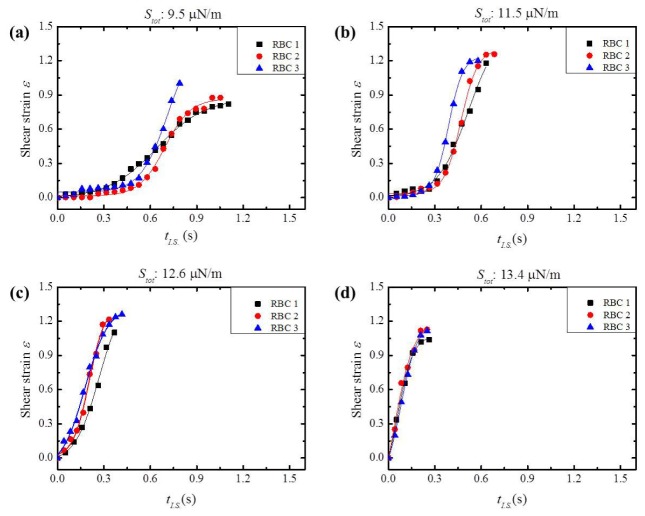
The time-dependent shear strain, ε(t) for irreversible stretching under various shear stress Stot induced by Bessel-like beams are summarized in Fig. 12, all of which were well-fitted by a Sigmoidal function with different fitting parameters. The strain was measured as a function of time until it reached maximum value at which single RBC finished to be stretched. Afterwards, strain maintained its maximum value under the constant stress loading. As shown in Fig. 12(a) and 12(b), the strain curves were well fitted to Sigmoidal function, showing a typical “S” shaped curve. As Stot further increased as in Fig. 12(c) and 12(d), the curves became almost linear, which indicates the deformation became more elastic with a shorter delay time t0. In a higher power Bessel beam might have increased the temperature of RBC membranes and water inside the cell to result in the behaviors in Fig. 12(c) and 12(d). This is the first experimental observation that the highly localized optical stretching of a single RBC could be correlated to a Sigmoidal function.
Fig. 12.
Time-dependent shear strain process for irreversible stretching in a creep retardation as a function of time under a step loading of different shear stress, Stot: (a) 9.5, (b) 11.5, (c) 12.6, and (d) 13.4 μN/m. All data were well-fitted by a Sigmoidal curve (solid line)
The fitting parameters εi, εf, τ*, and t0 were averaged for three red blood cells at each Stot loading and they are presented in Table 2. Among these parameters, it was found that εi and εf were not significantly affected by the optical shear stress Stot while t0 and τ*remarkably changed as we varied Stot. For example, as Stot changed from (a) 9.5 to (d) 13.4 μN/m, τ* and t0 decreased by a factor of 1.8 and 8.
It is previously reported that RBC temperature modified the retardation time τ* [27]. The change in τ* was categorized into a large decrease (~60%) range in 5 to 25°C and a small decrease (~7%) range in 25 to 45°C. In our experiments, the change in τ* was similarly categorized into a large decrease (~41%) range of Stot from 9.5 pN/m to 11.5 μN/m, and a small decrease (~8.1%) range Stot from 11.5 to 13.4 μN/m, as shown in Table 2. It is not possible to correlate these two ranges of Stot directly to the macroscopic average temperature ranges, but we can infer that there would be a temperature change at a highly localized beam spot on RBC because the tendency in τ* was similar in [27] and our experiments. In our experiments the macroscopic temperature of the total system was maintained at 25°C within 2°C variation, and the microfluidic channel serves as a sufficient reservoir to keep RBCs within the physiologically relevant temperature range. Further attempts to estimate the local temperature change by the correlating the shear stress Stot are being pursued by the authors.
5. Conclusion
We demonstrated a unique columnar deformation of RBC using dual fiber optic Bessel-like beams on a lab-on-a-chip system. The highly confined and non-diffracting nature from Bessel-like beams delivered larger peak surface stress in comparison to prior Gaussian beam reports, and resulted in a columnar deformation of RBC. The aspect ratio R of the stretched RBC revealed a clear distinction between the reversible stretching region (R~1.5) and the irreversible stretching region (R > 4.2). If the total stretching force Ftot acting on RBC was over ~18 pN, RBC underwent an irreversible columnar deformation. The irreversible stretching time tI.S. was well fitted to Kelvin/Voigt model in the linear viscoelasticity regime. We experimentally confirmed that tI.S. was highly dependent upon alcohol concentration and μRBC was quantitatively estimated and compared in different alcohol concentration. As a result, the plot of tI.S. versus the shear stress Stot gave a reasonable estimates of the elastic shear modulus μRBC, which can be used as a barometer for the health status of RBC. In the dynamic study of the columnar deformation, the plots of the shear strain ε versus the elapsed time t were found to be well-fitted to a Sigmoidal function for the first time. This has been widely used to define the response time of a medicine dose. Highly localized temperature change induced by Bessel-like beams and consequent changes in the viscosity and elastic modulus of RBC could have contributed to unique nonlinear viscoelastic behavior with irreversible columnar stretching. This lab-on-a chip provided near in situ analysis of the opto-mechanical behavior of individual RBC without post processing.
Supplementary Material
Acknowledgments
This work was supported in part by Institute of Physics and Applied Physics, Yonsei University, in part by ICT R&D Program of MSIP/IITP (2014-044-014-002), in part by Nano Material Technology Development Program through NRF funded by the MSIP (NRF-2012M3A7B4049800).
References and links
- 1.Ashkin A., Optical Trapping and Manipulation of Neutral Particles using Lasers (World Scientific, 2006) p. 99. [DOI] [PMC free article] [PubMed] [Google Scholar]
- 2.Ashkin A., Dziedzic J. M., Yamane T., “Optical trapping and manipulation of single cells using infrared laser beams,” Nature 330(6150), 769–771 (1987). 10.1038/330769a0 [DOI] [PubMed] [Google Scholar]
- 3.Hénon S., Lenormand G., Richert A., Gallet F., “A new determination of the shear modulus of the human erythrocyte membrane using optical tweezers,” Biophys. J. 76(2), 1145–1151 (1999). 10.1016/S0006-3495(99)77279-6 [DOI] [PMC free article] [PubMed] [Google Scholar]
- 4.Dao M., Lim C. T., Suresh S., “Mechanics of the human red blood cell deformed by optical tweezers,” J. Mech. Phys. Solids 51(11-12), 2259–2280 (2003). 10.1016/j.jmps.2003.09.019 [DOI] [Google Scholar]
- 5.Guck J., Ananthakrishnan R., Moon T. J., Cunningham C. C., Käs J., “Optical deformability of soft biological dielectrics,” Phys. Rev. Lett. 84(23), 5451–5454 (2000). 10.1103/PhysRevLett.84.5451 [DOI] [PubMed] [Google Scholar]
- 6.Guck J., Ananthakrishnan R., Mahmood H., Moon T. J., Cunningham C. C., Käs J., “The Optical Stretcher: A Novel Laser Tool to Micromanipulate Cells,” Biophys. J. 81(2), 767–784 (2001). 10.1016/S0006-3495(01)75740-2 [DOI] [PMC free article] [PubMed] [Google Scholar]
- 7.Ekpenyong A. E., Posey C. L., Chaput J. L., Burkart A. K., Marquardt M. M., Smith T. J., Nichols M. G., “Determination of cell elasticity through hybrid ray optics and continuum mechanics modeling of cell deformation in the optical stretcher,” Appl. Opt. 48(32), 6344–6354 (2009). 10.1364/AO.48.006344 [DOI] [PMC free article] [PubMed] [Google Scholar]
- 8.Gahagan K. T., Swartzlander G. A., Jr., “Optical vortex trapping of particles,” Opt. Lett. 21(11), 827–829 (1996). 10.1364/OL.21.000827 [DOI] [PubMed] [Google Scholar]
- 9.Grier D. G., Roichman Y., “Holographic optical trapping,” Appl. Opt. 45(5), 880–887 (2006). 10.1364/AO.45.000880 [DOI] [PubMed] [Google Scholar]
- 10.Durnin J., Miceli J. J., Jr, Eberly J. H., “Comparison of Bessel and Gaussian beams,” Opt. Lett. 13(2), 79–80 (1988). 10.1364/OL.13.000079 [DOI] [PubMed] [Google Scholar]
- 11.Garcés-Chávez V., McGloin D., Melville H., Sibbett W., Dholakia K., “Simultaneous micromanipulation in multiple planes using a self-reconstructing light beam,” Nature 419(6903), 145–147 (2002). 10.1038/nature01007 [DOI] [PubMed] [Google Scholar]
- 12.Siviloglou G. A., Broky J., Dogariu A., Christodoulides D. N., “Observation of accelerating Airy Beams,” Phys. Rev. Lett. 99(21), 213901 (2007). 10.1103/PhysRevLett.99.213901 [DOI] [PubMed] [Google Scholar]
- 13.Kim J., Jeong Y., Lee S., Ha W., Shin J.-S., Oh K., “Fourier optics along a hybrid optical fiber for Bessel-like beam generation and its applications in multiple-particle trapping,” Opt. Lett. 37(4), 623–625 (2012). 10.1364/OL.37.000623 [DOI] [PubMed] [Google Scholar]
- 14.Lee S. R., Kim J., Lee S., Jung Y., Kim J. K., Oh K., “All-silica fiber Bessel-like beam generator and its applications in longitudinal optical trapping and transport of multiple dielectric particles,” Opt. Express 18(24), 25299–25305 (2010). 10.1364/OE.18.025299 [DOI] [PubMed] [Google Scholar]
- 15.Prasad P. N., Introduction to Biophotonics (Wiley, New York, 2003) p. 163. [Google Scholar]
- 16.Ashok P. C., Marchington R. F., Mthunzi P., Krauss T. F., Dholakia K., “Optical chromatography using a photonic crystal fiber with on-chip fluorescence excitation,” Opt. Express 18(6), 6396–6407 (2010). 10.1364/OE.18.006396 [DOI] [PubMed] [Google Scholar]
- 17.S. Kim, “Prevention of blood cell adhesion, thrombosis, and hemolysis by means of saline perfusion”, Thesis doctoral from Biomedical engineering department in University of Iowa (1992) [Google Scholar]
- 18.Evans E. A., “New membrane concept applied to the analysis of fluid shear- and micropipette-deformed red blood cells,” Biophys. J. 13(9), 941–954 (1973). 10.1016/S0006-3495(73)86036-9 [DOI] [PMC free article] [PubMed] [Google Scholar]
- 19.Sewchand L. S., Rowlands S., Lovlin R. E., “Resistance to the Brownian Movement of Red Blood Cells on Flat Horizontal Surfaces,” Cell Biophys. 4(1), 41–46 (1982). 10.1007/BF02788554 [DOI] [PubMed] [Google Scholar]
- 20.Ward I. M., Sweeney J., “An Introduction to the Mechanical Properties of Solid Polymers, 2nd edition”, p. 65 (Wiley, 2005) [Google Scholar]
- 21.Lubarda V. A., Marzani A., “Viscoelastic response of thin membranes with application to red blood cells,” Acta Mech. 202(1-4), 1–16 (2009). 10.1007/s00707-008-0005-y [DOI] [Google Scholar]
- 22.Chien S., Sung K.-L. P., Skalak R., Usami S., Tözeren A., “Theoretical and experimental studies on viscoelastic properties of erythrocyte membrane,” Biophys. J. 24(2), 463–487 (1978). 10.1016/S0006-3495(78)85395-8 [DOI] [PMC free article] [PubMed] [Google Scholar]
- 23.Park Y., Diez-Silva M., Popescu G., Lykotrafitis G., Choi W., Feld M. S., Suresh S., “Refractive index maps and membrane dynamics of human red blood cells parasitized by Plasmodium falciparum,” Proc. Natl. Acad. Sci. U.S.A. 105(37), 13730–13735 (2008). 10.1073/pnas.0806100105 [DOI] [PMC free article] [PubMed] [Google Scholar]
- 24.Peng Z., Li X., Pivkin I. V., Dao M., Karniadakis G. E., Suresh S., “Lipid bilayer and cytoskeletal interactions in a red blood cell,” Proc. Natl. Acad. Sci. U.S.A. 110(33), 13356–13361 (2013). 10.1073/pnas.1311827110 [DOI] [PMC free article] [PubMed] [Google Scholar]
- 25.Deng J. L., Wei Q., Zhang M. H., Wang Y. Z., Li Y. Q., “Study of the effect of alcohol on single human red blood cells using near-infrared laser tweezers Raman spectroscopy,” J. Raman Spectrosc. 36(3), 257–261 (2005). 10.1002/jrs.1301 [DOI] [Google Scholar]
- 26.Shen L., Peterson S., Sedaghat A. R., McMahon M. A., Callender M., Zhang H., Zhou Y., Pitt E., Anderson K. S., Acosta E. P., Siliciano R. F., “Dose-response curve slope sets class-specific limits on inhibitory potential of anti-HIV drugs,” Nat. Med. 14(7), 762–766 (2008). 10.1038/nm1777 [DOI] [PMC free article] [PubMed] [Google Scholar]
- 27.Engelhardt H., Sackmann E., “On the measurement of shear elastic moduli and viscosities of erythrocyte plasma membranes by transient deformation in high frequency electric fields,” Biophys. J. 54(3), 495–508 (1988). 10.1016/S0006-3495(88)82982-5 [DOI] [PMC free article] [PubMed] [Google Scholar]
Associated Data
This section collects any data citations, data availability statements, or supplementary materials included in this article.


