Abstract
Geometrically continuous (Gk) constructions naturally yield families of finite elements for isogeometric analysis (IGA) that are Ck also for non-tensor-product layout. This paper describes and analyzes one such concrete C1 geometrically generalized IGA element (short: gIGA element) that generalizes bi-quadratic splines to quad meshes with irregularities. The new gIGA element is based on a recently-developed G1 surface construction that recommends itself by its a B-spline-like control net, low (least) polynomial degree, good shape properties and reproduction of quadratics at irregular (extraordinary) points. Remarkably, for Poisson’s equation on the disk using interior vertices of valence 3 and symmetric layout, we observe O(h3) convergence in the L∞ norm for this family of elements. Numerical experiments confirm the elements to be effective for solving the trivariate Poisson equation on the solid cylinder, deformations thereof (a turbine blade), modeling and computing geodesics on smooth free-form surfaces via the heat equation, for solving the biharmonic equation on the disk and for Koiter-type thin-shell analysis.
Keywords: Isogeometric finite element, Isoparametric method, Geometric continuity, Extraordinary point, Irregular quad mesh, Multi-sided facets, Bi-quadratic
1. Introduction
Isogeometric Analysis (IGA), as introduced in [13], is an isoparametric framework of numerical analysis that uses spline functions to represent both the geometric domain and the approximate solution of a partial differential equation (PDE). Where the partition of the geometric domain has irregularities, e.g. differs from the regular tensor-product spline lattice by having n = 3 or n > 4 quadrilateral domain pieces (patches) come together, the geometric design community has developed several extensions of the tensor-product (NURBS) representation. The two most widely-used representations are geometrically continuous (Gk) complexes of finitely many piecewise polynomial spline patches; and generalized subdivision surfaces that are defined by an infinite sequence of nested Ck surface rings and whose pieces can be viewed as subdivision splines with singularities at the irregular points [21]. Such subdivision splines have been used for finite element analysis as early as [8,9], but most recently received renewed attention, this time from the IGA community [1,18]. Since subdivision splines are naturally refinable, this approach is likely to gain a lot of traction once the computer-aided design community adopts subdivision into their design flow.
This paper focuses on the alternative approach of building isogeometric elements from geometrically continuous surface (Gk) constructions. This approach leverages the observation that any Gk construction yields Ck isogeometric finite elements by composing a Gk analysis function with the inverse of an equally Gk-parameterized physical domain [18,20] (see also the linear G1 reparameterization in [16]). Gk complexes built from polynomial or rational tensor-product spline patches or patches in the Bernstein–Bézier form (BB-form) are automatically compatible with the industrial NURBS exchange standard, one of the goals of IGA [22,24].
In this paper, we specifically focus on a recently-developed G1 construction [15] that extends bi-quadratic (bi-2) splines to more general quad meshes that can include non-4-valent points and multi-sided facets. The G1 construction defines n patches of degree bi-3 in BB-form where n = 3 or n = 5 come together, respectively n patches of degree bi-4 where more than five patches join. (This distinction between the valences near the regular case of n = 4 and higher valences is both geometrically motivated and relevant in practice where the majority of irregularities are of valence 3 and 5.) The construction in [15] differs from the work in [4,22,25] in that it does not require solving equations while constructing the physical domain: the domain and the elements are modeled analogous to splines in B-spline form. That is, control points carry the geometric information and evaluation and differentiation amount to explicit formulas in terms of the control points. Shape optimization is integrated into the explicit formulas that relate the control net to their explicit piecewise Bézier representation. Rather than exploring the full space of available G1 reparameterizations, as do two recent reports [4,14], we have selected a specific construction developed by careful consideration of the space of low-degree G-constructions.
Besides the low degree, our interest in developing this construction was piqued by the fact that, in order to create good reflection lines, the construction [15] offers high polynomial reproduction at the irregular points where n quadrilateral surface pieces meet. This property, known in the geometric design community as flexibility, is desirable both to increase smoothness and to ensure a rich gamut of shape. The observed numerical convergence shows that high flexibility is not only good for the surface quality but also for the numerical approximation order of gIGA elements: For a symmetric tessellation of the disk using interior vertices of valence 3 for Poisson’s equation, we observe O(h3) convergence of the error not only in the L2, but also in the L∞ norm. This is in line with the optimal rate for bi-2 splines.
Overview
Section 2 reviews geometric continuity and Section 3 the derivation of the C1 isogeometric element from a G1 (surface) construction. Section 4 reports the performance of our implementation on several benchmark problems, including Poisson’s equation (where smoothness of the elements is not needed), the heat equation on free-form surfaces (where smoothness is needed to model the surface), the biharmonic equation and thin place analysis (where the solution requires smooth elements).
2. Review of geometric continuity
Two Ck curve segments x1 : [0‥1] → ℝ and x2 : [0‥1] → ℝ join Gk at a common point x1(1) = x2(0) if, possibly after a change of variables, derivatives match at the common point [5]. Generalizing this notion to edge-adjacent patches yields one of several equivalent notions of geometric continuity of surfaces as explained in the survey of geometric continuity [19, Section 3].
A convenient definition for the general multi-variable setup uses the classical notion of a k-jet of an ℝd-valued Ck map defined on an open neighborhood of a point s ∈ ℝm, m, d ≥ 1. This notion will help us to formally capture agreement of expansions of two maps at a common point or a set of common points forming a shared interface between two regions. For our application, d, m ∈ {2, 3}. For an integer k ≥ 1, the k-jet is an equivalence class on the set of pairs
For each m-tuple i ≔ (i1,…, im) consisting of non-negative integers ij, define |i| ≔ Σij, and let ∂i denote the |i|th-order partial-differentiation operator . The relation on ℱs, d defined by
is an equivalence relation, and the equivalence class of f under is the k-jet of f at s, denoted Note that |i| = 0 implies f1(s) = f2(s). Composition of jets is well-defined, also for jets on half-spaces that are used in our context of piecemeal-defined geometry.
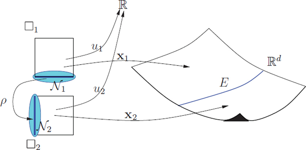
The challenge addressed by geometric continuity is that the two maps whose jets are matched, each have their separate parameter domains. A change of variables, the reparameterization ρ, is needed to relate them to one another. More formally, for α = 1, 2, let □α ⊂ ℝm be an m-dimensional polytope, for our applications a unit square or cube, and let Eα be an (m − 1)-dimensional facet of □α, with interior int(Eα) =E̊α where P̊ denotes the interior with respect to the smallest space enclosing P. For our scenario, Eα is the interval [0,…, 1] when m = 2 and its tensor [0‥1]2 when m = 3. Then, following [12], we define ρ : 𝒩1 → 𝒩2 to be a Ck diffeomorphism between two open sets 𝒩1, 𝒩2 ⊂ ℝm that enclose E̊1 and E̊2 respectively such that ρ: (E̊1) =E̊2, ρ(𝒩1∩□̊1) = 𝒩2 \ □2 and ρ(𝒩1 \ □1) = 𝒩2∩□̊2.
With the help of the reparameterization ρ, we can relate the two maps and define a Gk relation as follows. Let xα : □α ⊂ ℝm → ℝd, α ∈ {1, 2} be Ck maps for which
the images of the xα therefore join along a common interface E ≔ x2(E2) = x1 (E1). We say that x1 joins x2 Gk with reparameterization ρ along E if for every s ∈ E̊1 we have
| (1) |
i.e. the jets match after reparameterization.
As a simplest example, when m = 1 and d = 2, and the xα are polynomial pieces then each □α is a line segment and E is the common point shared by the planar curve pieces x1(□1) and x2(□2). In one of our scenarios (see Fig. 1, when m = 2, d = 3, and the xα are tensor-product splines then each □α is a rectangle and E is a boundary curve shared by the surface pieces x1 (□1) and x2(□2).
Fig. 1.
gIGA elements and Gk continuity.
3. Construction of the C1 iso-geometric elements
In the isoparametric approach to solving partial differential equations, maps xα, α = 1, 2,…, nf, parameterize a region or a manifold Ω called the physical domain. The physical domain is tessellated into pieces xα (□α),
| (2) |
In the numerical experiments of this paper, we apply the approach for m = 2 and d = 2, where Ω is a region of the xy-plane, for m = 2 and d = 3, where Ω is a surface embedded in ℝ3 and for m = d = 3 where Ω is a (solid) region in ℝ3. The goal is to compute the coefficients of a linear combination of nf analysis functions uα : □α → ℝ such that the composed map solves the partial differential equation at hand on xα(□α). The function
| (3) |
is called an isogeometric element if the scalar component functions of both uα and xα are drawn from the same function space, here the space of tensor-product spline functions on □α [6,13]. Then [12,20] show that any two edge-adjacent isogeometric elements join Ck on the physical domain if they are built, as in (3), from Gk-joined geometry maps xα and equally reparameterized and Gk-joined analysis functions uα.
We leverage this insight to build C1 isogeometric elements on general quad meshes and, by extension, for special volumetric meshes. Specifically, we leverage the recently-developed G1 surface construction [15] that yields B-spline-like functions Ni for irregular control-nets. Four properties recommend these Ni for building an isogeometric element.
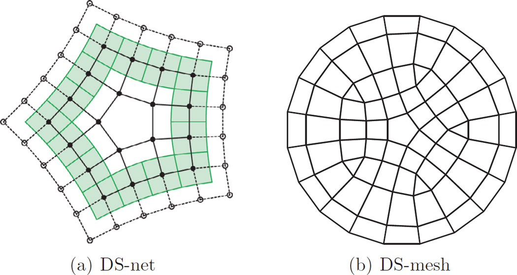
First, the degrees of freedom for analysis are in an intuitive 1–1 relation with the degrees of freedom for modeling the physical domain via a DS-mesh. In a DS-mesh all nodes have valence four and n-sided facets are surrounded by one ring of quadrilaterals (forming DS-nets as in Fig. 2a). Each node i of the DS-mesh acts as a degree of freedom associated with one Ni, analogous to B-spline coefficients of bi-2 tensor-product splines. The Ni and the B-splines together form a partition of 1. A DS-mesh can be obtained from any input mesh by Doo–Sabin subdivision [11], by dualizing if the input mesh consists only of quadrilaterals, or by local conversion of non-4-valent vertices (see [15]).
Second, the Ni has low polynomial degree. In fact the degree is likely least for piecewise tensor-product functions unless we accept reduced flexibility, i.e. unless we accept that not all lower-order terms of the Taylor expansion can be reproduced at the irregular point. Minimal degree implies smaller support than similar smooth surface constructions (e.g. [18]), reducing the element overlap and hence the density of the system to be solved.
Third, the Bernstein–Bézier (BB) coefficients of the pieces of the Ni are tabulated. No system of equations has to be solved to derive, from an input quad mesh or its dual mesh, the coefficients of the geometry map or the analysis function: the isogeometric elements are determined as a linear combination of the tabulated BB-coefficients. Together with the low degree, this implies low computational cost when assembling the linear finite element system.
Fourth, the construction has increased smoothness and quadratic flexibility at the irregular point. That is, analogous to polynomial reproduction of functions, all quadratic expansions at the irregular point can be modeled. This flexibility was built into the surface construction to yield well-distributed highlight lines even for complex geometric surface blends; in the isogeometric context second-order flexibility is needed to obtain better than O(h2) convergence of the L∞ error.
Fig. 2.
(a) The solid lines form a DS-net here with a central, isolated n = 5-sided facet: one layer of quadrilaterals (4n nodes) surround the n-sided facet. The green patches in the regular extension are bi-2 spline patches. (b) A DS-mesh consist of DS-nets (here n = 3, 5) and regular, tensor-product sub-nets defining a bi-2 spline. (For interpretation of the references to color in this figure legend, the reader is referred to the web version of this article).
For the regular regions of the mesh, the G1 construction [15] uses biquadratic (bi-2) splines as the simplest choice for converting a regular quad mesh into a smooth tensor-product spline surface. Surrounding the irregularities, e.g. when n = 3, 5 or more quadrilaterals join, the construction uses n pieces of degree bi-3 when n ∈ {3, 5} and n pieces of degree bi-4 when n > 5. All regular nodes of the DS-mesh, i.e. nodes not part of a DS-net, can then be interpreted as control points of a bi-2 spline. Only for the n patches surrounding the central point are special formulas needed whose derivation is detailed in [15]. The formulas define all patches in tensor-product Bernstein–Bézier (BB) form ofbi-degree p
| (4) |
where is the kth Bernstein–Bézier polynomial of degree p and fk1k2 are its BB-coefficients.
Assembly of the finite element system
The publication [15] shows how to generate the formulas for expressing a G1 function in terms of its DS-net.1 For each valence n ∈ {3, 5, 6, 7,…}, these formulas can be aggregated as columns of a sparse matrix Mn: each column i of Mn lists the BB-coefficients of the G1-joined functions output by the algorithm in [15] when the control point ci of the DS-net is given the value 1 and all other control points the value 0. That is, each column represents the BB-coefficients of a piecewise function Ni (of degree bi-3 where n = 3, 5 and of degree bi-4 where n > 5) – akin to expressing a bi-2 tensor-product spline basis function in terms of polynomial pieces in BB-form.
The matrix applies separately to each coordinate of the domain and to the analysis function. Due to the structural symmetry of the DS-net (not to be confused with geometric symmetry) only four columns of the matrix need to be known – corresponding to the four mesh points of one sector that are closest to the central multi-sided facet (see Fig. 2a).
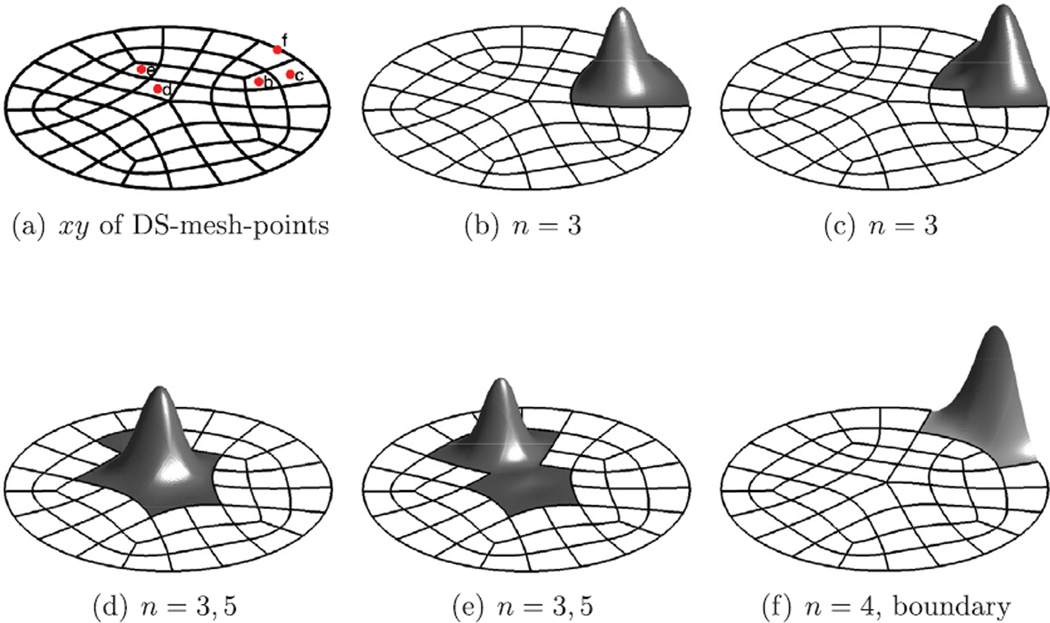
With the well-known bi-2 B-spline to Bézier conversion defining the pieces corresponding to the regular mesh and the sparse matrices defining the pieces joining at irregular points, we obtain, for each choice of control net, a function that is C1 where the net is regular and G1 where it is irregular. We can treat all control points as if they were B-spline control points and associate with each control point i an isogeometric function bi that is a union of isogeometric elements, i.e. their restriction to a domain piece is defined as (Fig. 3)
| (5) |
(By default, the functions Nα, i and the patches xα are polynomial; but they can also be embedded in homogeneous space to model quadrics and boundary conics.)
Fig. 3.
Isogeometric elements on the unit disk. The unit disk is partitioned into patches xα whose boundaries run dual to the input DS-mesh (cf. Fig. 2b). The support of the irregular bi is that of bi-2 B-splines taking into account that some facets are n-gons. (a) shows the xy-coordinates of DS-mesh control points of the irregular isogeometric elements (b–e) as well as a regular boundary element (f).
We can now assemble the stiffness matrix and the right-hand-side of the PDE system in standard fashion (see e.g. [7]), by looping over each patch xα(□) to integrate the (derivatives of the) scalar-valued tensor-product isogeometric elements bi restricted to xα The exact circular boundary geometry is captured by endowing the outermost layer of control points with the appropriate rational weights.
4. Numerical experiments and convergence rates
This section reports on the performance of our implementation on a series of benchmark problems and their generalizations: solving Poisson’s equation on the unit disk, solving Poisson’s equation on a solid free-form cylinder (and its deformation in the shape of a turbine blade), solving the biharmonic equation on the unit disk, solving the heat equation on smooth free-form surfaces to obtain a geodesic parameterization, and solving the Scorderlis–Lo roof benchmark problem of Koiter’s thin-shell analysis. The unit disk is chosen as the domain because it cannot be mapped out by a singularity-free NURBS patch: modeling the unit disk requires multiple patches that join at irregular (extraordinary) points if the patches themselves are regular. For other scenarios, where a regular patch layout is feasible, such as the Scrodelis–Lo roof, we intentionally introduced irregularities to test whether our approach reduces the convergence order (it does not).
4.1. Poisson’s equation
The new C1 gIGA elements are intended for solving (i) higher-order partial differential equations where C0 elements do not provide the correct solution space or (ii) differential equations on smooth surfaces where C0 elements do not provide the correct shape. For Poisson’s equation C0 elements on separate quads suffice and yield optimal convergence. But since Poisson’s equation on the disk is a standard problem, we add it as a basic check. For d = 2 and later for d = 3, we want to solve Poisson’s equation on a domain Ω ⊆ ℝd subject to homogeneous conditions on the boundary ∂Ω of Ω and with f ∈ H0(Ω)
| (6) |
In its weak form, this amounts to finding such that for all
| (7) |
Numerically, we compute an approximate solution in terms of the isogeometric functions bi defined in (5), by determining the coefficients, ci ∈ ℝ, i = 1, 2,…, nν of . By construction, each ci is associated with one node of the input net. Following Galerkin’s approach, we set ν = bi in Eq. (7) and obtain the constraints:
| (7*) |
These yield the system of linear equations
| (8) |
in the vector of unknown coefficients c ≔ [c1,…,cnν]τ. We define the physical domain, Ω as in Eq. (2) (where all □α = □) and write the integrals in Eq. (8) as a sum of integrals restricted to the pieces of the physical domain, the patches xα(□), α ∈ {1,2,…,nf}. By change of variables, the local integrals with respect to each parameter domain □ are:
where Jα is the transpose of the Jacobian of the map xα.
Example 1
We consider Poisson’s equation (6) on the disk Ω ≔ {(x, y) ∈ ℝ2 : x2 + y2 < 1} with f ≔ 1. The exact solution is u = (1 − x2 − y2)/4. When refining we have two choices: to preserve the parameterization of the geometry by applying DeCasteljau’s algorithm or to refine the control net by applying one step of a subdivision algorithm. Both choices guarantee exact replication of the disk, albeit with slightly different parameterization. We opted for applying subdivision steps since this trivially implies that the analysis and the geometry maps are equally reparameterized as required for invoking the theory of [12,20]. In the following, we record the number of subdivision steps as level ℓ with the first DS-mesh carrying the label ℓ = 1.
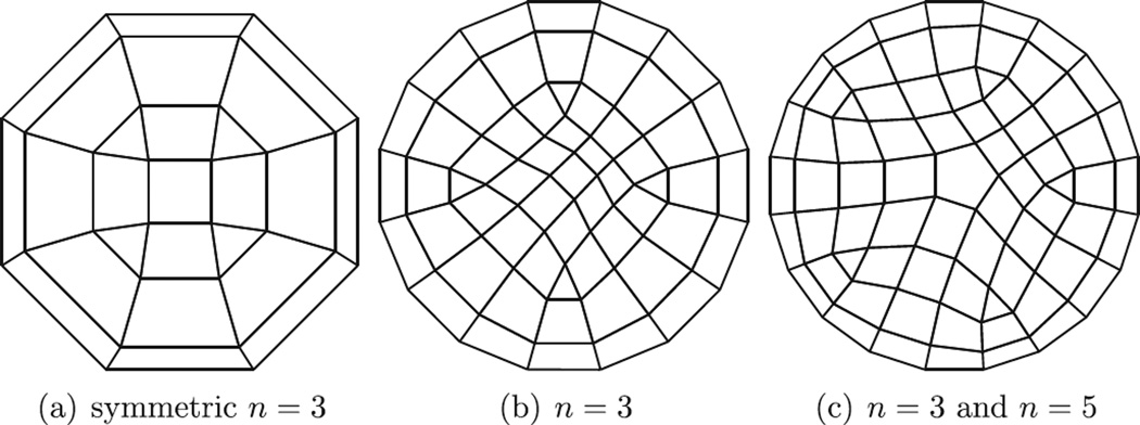
Tables 1, 2 and 3 list the L2, L∞ and H1 errors and the corresponding convergence rate measured for our new isogeometric elements on symmetric and asymmetric quad meshes Fig. 4a and b and meshes including nodes of higher valence Fig. 4c. The error after five Doo–Sabin subdivision steps is displayed in Fig. 5. The stable convergence rates of roughly 23 in the L2 norm are in line with the convergence order of the regular spline scenario. (For L2, [2] shows the convergence rate to be optimal.) Remarkably, for the symmetric layout (a), also the L∞ norm measures and estimates a convergence rate of O(h3). While the L∞ convergence rate is lower for the asymmetrically perturbed layouts (b) and (c), the absolute error is on par and unaffected by this perturbation, also when introducing a node of valence 5.
Table 1.
Error and estimated rate of convergence (e.r.c.) of gIGA elements in the L2, L∞ and H1 norms for Poisson’s equation Fig. 4a.
| Poisson’s equation on (a) | ||||||
|---|---|---|---|---|---|---|
| ℓ | ‖u − uh‖L2 | e.r.c. L2 | ‖u − uh‖L∞ | e.r.c. L∞ | ‖u − uh‖H1 | e.r.c. H1 |
| 1 | 2.0e-3 | – | 3.0e-3 | – | 2.2e-2 | – |
| 2 | 5.4e-4 | 3.7 | 9.7e-4 | 3.1 | 9.7e-3 | 2.3 |
| 3 | 5.4e-5 | 10.0 | 1.3e-4 | 7.5 | 2.0e-3 | 4.9 |
| 4 | 5.2e-6 | 10.3 | 1.7e-5 | 7.7 | 4.5e-4 | 4.5 |
| 5 | 5.3e-7 | 9.8 | 2.1e-6 | 7.9 | 1.0e-4 | 4.3 |
Table 2.
Error and estimated rates of convergence of gIGA elements in the L2, L∞ and H1 norms for Poisson’s equation on the disk of Fig. 4b.
| Poisson’s equation on (b) | ||||||
|---|---|---|---|---|---|---|
| ℓ | ‖u − uh‖L2 | e.r.c. L2 | ‖u − uh‖L∞ | e.r.c. L∞ | ‖u − uh‖H1 | e.r.c. H1 |
| 1 | 3.6e-4 | 0 | 6.2e-4 | – | 6.8e-3 | – |
| 2 | 7.5e-5 | 4.8 | 2.0e-4 | 3.6 | 2.7e-3 | 2.5 |
| 3 | 7.6e-6 | 9.8 | 2.1e-5 | 8.2 | 6.2e-4 | 4.4 |
| 4 | 8.0e-7 | 9.5 | 3.4e-6 | 6.2 | 1.5e-4 | 4.2 |
| 5 | 9.0e-8 | 8.9 | 5.8e-7 | 5.9 | 3.5e-5 | 4.2 |
Table 3.
Error and estimated rates of convergence of gIGA elements in the L2, L∞ and H1 norms for Poisson’s equation on the Fig. 4c.
| Poisson’s equation on (c) | ||||||
|---|---|---|---|---|---|---|
| ℓ | ‖u − uh‖L2 | e.r.c. L2 | ‖u − uh‖L∞ | e.r.c. L∞ | ‖u − uh‖H1 | e.r.c. H1 |
| 1 | 4.1e-4 | – | 1.0e-3 | – | 6.9e-3 | – |
| 2 | 2.1e-4 | 2.0 | 6.9e-4 | 1.5 | 5.6e-3 | 1.2 |
| 3 | 1.9e-5 | 10.9 | 8.7e-5 | 7.9 | 1.2e-3 | 4.8 |
| 4 | 1.9e-6 | 10.2 | 2.1e-5 | 4.2 | 2.6e-4 | 4.4 |
| 5 | 2.1e-7 | 9.0 | 4.9e-6 | 4.2 | 6.3e-5 | 4.2 |
Fig. 4.
DS-mesh (Doo–Sabin subdivision level ℓ = 1).
Fig. 5.
Error plots at Doo–Sabin subdivision level ℓ = 5. The scale is 10−6,10−7 and 10−6 respectively.
Example 2
Next, we consider Poisson’s equation (6) on a trivariate cylinder. Here Ω ≔ {(x, y, z) ∈ ℝ3 : x2 + y2 < 1 and 0 < z < 1} and f ≔ 1 − x2 − y2 − 2z2 + 2z. The exact solution is u = (1 − x2 − y2)z(l − z)/2. We model the xy-cross-sections with [15] and interpret the B-spline-like control points of this representation as quadratic B-spline control points when tensoring in the z-direction. Table 4 displays the resulting L2 and L∞ errors and the corresponding convergence rate. The error is also visualized in Fig. 6. The ratios in the table point to O(h3) convergence also in the L∞ norm.
Table 4.
gIGA convergence results for Possion’s equation on the cylinder.
| ℓ | ‖u − uh‖L2 | e.r.c. | ‖u − uh‖L∞ | e.r.c. | ‖u − uh‖H1 | e.r.c. |
|---|---|---|---|---|---|---|
| 1 | 7.2e-04 | – | 1.4e-03 | – | 8.5e-3 | – |
| 2 | 1.9e-04 | 3.7 | 4.7–04 | 3.0 | 3.6e-3 | 2.3 |
| 3 | 2.0e-05 | 9.9 | 6.3–05 | 7.4 | 7.5-04 | 4.8 |
| 4 | 1.9e-06 | 10.3 | 8.3–06 | 7.6 | 1.6e-04 | 4.6 |
Fig. 6.
Poisson’s equation on the cylinder: the exact solution and error plots visualized on horizontal slices. The scale of (b) is 10−4, the scale of (c) is 10−5.
Example 3
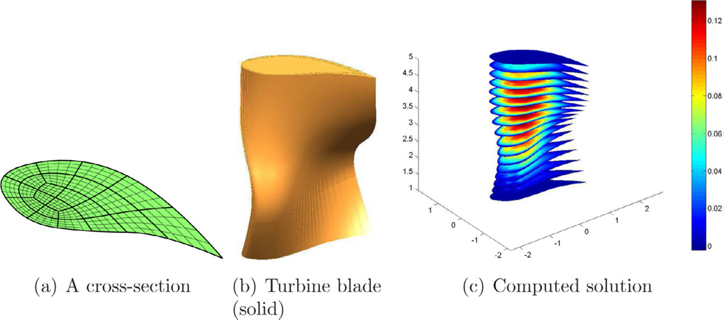
We demonstrate that our method is also applies to Poisson’s equation on generalized cylinders. We solve Poisson’s equation within a volumetric turbine blade by modeling cross sections as air-foils using [15]. Each air-foil has three points of valence 3 (see Fig. 7a which also shows iso-parameter lines on the patches). Then we form the volumetric blade (Fig. 7b) as the tensor of the air-foils with quadratic B-splines, i.e. in the orthogonal direction, we interpret the vertices of the airfoil as B-spline control points. The computational results for Poisson’s equation with f ≔ 1 are displayed in Fig. 7c. Nothing restricts the airfoils to be planar. The base shape can be replaced by arbitrary smooth free-form shapes modeled from regular tensor-product sub-nets, converted n-valent vertex neighborhoods and DS-nets.
Fig. 7.
Poisson’s equation on the volumetric turbine blade model.
4.2. The biharmonic equation
Since our elements are C1 on their physical domain, their main use is to model higher-order differential equations that require C1 continuity. The biharmonic equation on the domain Ω subject to homogeneous boundary conditions on the boundary ∂Ω of
| (9) |
where n is the outward normal on ∂Ω and f ∈ H0(Ω). Reformulated in the weak form, we seek such that for all
holds. Since , the test function v must be C1 smooth. Our method satisfies this critical requirement. We use the Galerkin’s projection to discretize the weak form. Analogous to our treatment of Poisson’s equation, we transform, by change of variables, integrals over Ω to integrals over the reference domain □. Finally, we solve the linear system to obtain a numerical solution for the harmonic equation.
Example 4
We consider the biharmonic equation (9) on the unit disk, i.e. with Ω ≔ {(x, y) ∈ ℝ2 : x2 + y2 < 1} and f ≔ (8π2 − π4(x4 + 2x2y2 + y4) sin (π (x2 + y2)/2) +8π3(X2 + y2) cos (π(x2 + y2)/2). The exact solution is u = 1 − sin (π(x2 + y2)/2). Fig. 8 displays the respective errors at high refinement for the layouts of Fig. 4. Tables 5, 6 and 7 tabulate the L2, L∞ and H1 errors and the estimated convergence rates. Convergence rates stabilizing at or just below 22 indicate a convergence order of O(h2) for the L2, L∞ and the H1 error, in line with tensor-product biquadratic elements on rectangular domains. Remarkably, symmetry or valence do not affect the observed error magnitude or convergence rate. These numerical results match theoretical results presented in [23] predicting an L2 error convergence order of O(hp) when using basis functions of degree p.
Fig. 8.
Error plots at level ℓ =5. The scale is respectively 10−4,10−4 and 10−3.
Table 5.
gIGA convergence results for the biharmonic equation on the disk of layout Fig. 4a.
| The biharmonic equation | ||||||
|---|---|---|---|---|---|---|
| ℓ | ‖u − uh‖L2 | e.r.c. L2 | ‖u − uh‖L∞ | e.r.c. L∞ | ‖u − uh‖H1 | e.r.c. H1 |
| 1 | 0.03 | – | 2.9e-2 | – | 0.14 | – |
| 2 | 0.02 | 1.6 | 3.2e-2 | 0.9 | 7.6e-2 | 1.8 |
| 3 | 6.0e-3 | 3.3 | 9.3e-3 | 3.4 | 2.2e-2 | 3.5 |
| 4 | 1.7e-3 | 3.5 | 2.6e-3 | 3.6 | 5.9e-3 | 3.7 |
| 5 | 5.0e-4 | 3.4 | 7.0e-4 | 3.7 | 1.6e-3 | 3.7 |
Table 6.
gIGA convergence results for the biharmonic equation on the disk of layout Fig. 4b.
| The biharmonic equation | ||||||
|---|---|---|---|---|---|---|
| ℓ | ‖u − uh‖L2 | e.r.c. L2 | ‖u − uh‖L∞ | e.r.c. L∞ | ‖u − uh‖H1 | e.r.c. H1 |
| 1 | 9.3e-2 | – | 9.1e-2 | – | 2.8e-1 | – |
| 2 | 3.6e-2 | 2.6 | 4.9e-2 | 1.8 | 1.1e-1 | 2.6 |
| 3 | 9.4e-3 | 3.8 | 1.3e-2 | 3.8 | 2.9e-2 | 3.9 |
| 4 | 2.5e-3 | 3.8 | 3.4e-3 | 3.8 | 7.5e-3 | 3.8 |
| 5 | 6.7e-3 | 3.8 | 9.0e-4 | 3.8 | 1.9e-3 | 3.8 |
Table 7.
gIGA convergence results for the biharmonic equation on the disk of layout Fig. 4c.
| The biharmonic equation | ||||||
|---|---|---|---|---|---|---|
| ℓ | ‖u − uh‖L2 | e.r.c. L2 | ‖u − uh‖L∞ | e.r.c. L∞ | ‖u − uh‖H1 | e.r.c. H1 |
| 1 | 0.15 | – | 0.11 | – | 0.46 | – |
| 2 | 0.039 | 3.8 | 0.032 | 3.5 | 0.12 | 3.8 |
| 3 | 9.8e-3 | 3.9 | 0.008 | 4.0 | 0.03 | 4.0 |
| 4 | 2.5e-3 | 3.9 | 0.002 | 4.0 | 7.7e-3 | 4.0 |
| 5 | 6.2e-4 | 4.0 | 5.1e-4 | 4.0 | 1.9e-4 | 4.0 |
4.3. The heat equation and geodesics on surfaces
The heat equation of a surface x may be written as ut − δΔxu = f where δ is the thermal diffusivity and f is a heat source. The Laplace–Beltrami operator is written as Δx = ∇x · ∇x. The gradient operator on the surface is defined as
for any function ψ defined on the surface x where [gij] is the inverse of the first fundamental form matrix of x. The numerical scheme to discretize the Laplace–Beltrami operator Δx is analogous to the one used for Laplace operator in 2D. We use Newmark’s method to discretize the time variable.
Example 5
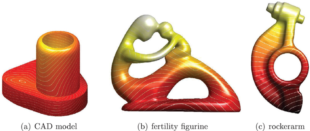
In [10], the heat equation was used to compute geodesic curves between a source point and arbitrary points on a polyhedral mesh. Here, we reproduce their method but for a smooth surface. Fig. 9 illustrates the geodesic distances for three models (from a source point at the bottom).
Fig. 9.
Geodesics via the heat equation and using gIGA elements.
4.4. Koiter’s thin-shell analysis
Koiter’s shell model [17] is based on Kirchhoff–Love assumptions: lines normal to the ’middle surface’ in the original configuration x̄ remain normal to the middle surface in the deformed configuration x, and there is no transverse shear strain and stress. Under these assumptions, the undeformed and deformed shell are parameterized by
| (10) |
| (11) |
where h is the thickness of the shell. With the notation (․)α ≔ ∂(․)/∂θα, α = 1, 2, the membrane strain and the bending strain βij ≔ xi․(a3)j − x̄i․(ā3)j, the Green–Lagrange strain tensor is
| (12) |
Then the displacement vector field u(θ1, θ2) = x(θ1, θ2) − x̄(θ1, θ2) of the thin shell is found by minimizing the total potential energy function
| (13) |
where b is the body force and t is the traction on some parts Γt of the shell. E and ν are the Young modulus and Poisson’s ratio, respectively.
Example 6
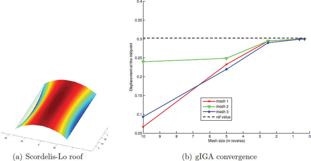
We compute the Scorderlis–Lo roof benchmark problem of the shell obstacle course in [3]. We model the roof as x ≔ (x, y, z(x, y)) where the map (x, y) : ℝ2 → ℝ2 is modeled by our algorithm and where the map z(x, y) is the analytical height function. To measure the impact of irregular (extraordinary) points, we consider three different layouts for (x, y) shown in Fig. 10. The results of the analysis are compared in Fig. 11 by tracking the maximum displacement (of the midpoint on the edge aligned with the cylinder’s axis). We see that, regardless of the layout pattern, the value converges to the benchmark value.
Fig. 10.
Three different layouts for the Scordelis–Lo roof.
Fig. 11.
gIGA convergence of the displacement of the Scordelis–Lo roof to the benchmark.
5. Conclusion
We exhibited a new class of generalized isogeometric analysis (gIGA) elements based on the G1 surface construction [15]. The G1 construction takes as input a B-spline-like control net that generalizes bi-quadratic splines by allowing multi-sided facets and non-4-valent points (that get converted to DS-nets). The degrees of freedom of the analysis are the nodes of the resulting DS-mesh. The minimal degree of the surface pieces yields a smaller support than similar smooth surface constructions, reducing the element overlap and hence the density of the system to be solved. (We do not claim that only low degree leads to small support or that all low-degree smooth constructions yield sparsity.) Tensoring bivariate control nets with B-splines in a third variable straightforwardly yields a class of volumetric isogeometric elements. Composition of the G1 construction allows reparameterizing (and solving) Koiter-type thin-shell problems.
The new C1 gIGA elements can solve higher-order partial differential equations where C0 elements do not provide the correct solution space, and apply to smooth surfaces, where C0 elements do not provide the correct shape. Remarkably, for a number of well-known challenge problems with irregularities in the layout, the gIGA element exhibits the same convergence rates and quality of output as bi-2 tensor-product B-splines on the regular tensor-product grid. Overall this demonstrates that isogeometric elements built from G-continuous (surface) constructions can be effective extensions of the tensor-product B-spline based approach of Hughes et al. [13].
Acknowledgments
Work supported by the National Science Foundation under Grant CCF-1117695 and NIH Grant R01-EB018625.
Footnotes
The derivation is not replicated here; please see [15].
References
- 1.Barendrecht PJ. Isogeometric Analysis with Subdivision Surfaces. 2013 [Google Scholar]
- 2.Bazilevs Y, Beirao da Veiga L, Cottrell J, Hughes T, Sangalli G. Isogeometric analysis: approximation, stability and error estimates for h-refined meshes. Math. Models Methods Appl. Sci. 2006;16:1031–1090. [Google Scholar]
- 3.Belytschko T, Stolarski H, Liu WK, Carpenter N, Ong JS. Stress projection for membrane and shear locking in shell finite elements. Comput. Methods Appl. Mech. Eng. 1985;51:221–258. [Google Scholar]
- 4.Bercovier M, Matskewich T. Smooth Bézier Surfaces Over Arbitrary Quadrilateral Meshes. http://arxiv.org/abs/1412.1125. [Google Scholar]
- 5.Boehm W. On the definition of geometric continuity. Comput.-Aided Des. 1988;20:370–372. Letter to the Editor. [Google Scholar]
- 6.de Boor C. A Practical Guide to Splines. Springer; 1978. [Google Scholar]
- 7.Borden MJ, Scott MA, Evans JA, Hughes TJ. Isogeometric finite element data structures based on Bézier extraction of NURBS. Int. J. Numer. Methods Eng. 2011;87:15–47. [Google Scholar]
- 8.Cirak F, Ortiz M, Schröder P. Subdivision surfaces: a new paradigm for thin-shell finite-element analysis. Int. J. Numer. Methods Eng. 2000;47:2039–2072. [Google Scholar]
- 9.Cirak F, Scott M, Antonsson EK, Ortiz M, Schröder P. Integrated modeling, finite-element analysis, and engineering design for thin-shell structures using subdivision. Comput.-Aided Des. 2002;34:137–148. [Google Scholar]
- 10.Crane K, Weischedel C, Wardetzky M. Geodesics in heat: a new approach to computing distance based on heat flow. ACM Trans. Graph. 2013;32:152. [Google Scholar]
- 11.Doo D, Sabin M. Behaviour of recursive division surfaces near extraordinary points. Comput.-Aided Des. 1978;10:356–360. [Google Scholar]
- 12.Groisser D, Peters J. Matched Gk-constructions always yield Ck-continuous isogeometric elements. Comput. Aided Geom. Des. 2015;34:67–72. doi: 10.1016/j.cagd.2015.02.002. [DOI] [PMC free article] [PubMed] [Google Scholar]
- 13.Hughes TJR, Cottrell JA, Bazilevs Y. Isogeometric analysis: CAD, finite elements, NURBS, exact geometry and mesh refinement. Comput. Methods Appl. Mech. Eng. 2005;194:4135–4195. [Google Scholar]
- 14.Kapl M, Vitrih V, Jüttler B. Isogeometric Analysis with Geometrically Continuous Functions. 2014 Technical Report 22, Johannes Kepler University, G+S. [Google Scholar]
- 15.Karčiauskas K, Peters J. Smooth multi-sided blending of biquadratic splines. Comput. Graph. 2014;46:172–185. [Google Scholar]
- 16.Kiendl J, Bletzinger KU, Linhard J, Wüchner R. Isogeometric shell analysis with Kirchhoff–Love elements. Comput. Methods Appl. Mech. Eng. 2009;198:3902–3914. [Google Scholar]
- 17.Koiter W. On foundations of linear theory of thin elastic shells. I Proceedings of K. Ned. Akad. Wet., Ser. B Phys. Sci. 1970;73:169. [Google Scholar]
- 18.Nguyen T, Karčiauskas K, Peters J. A comparative study of several classical, discrete differential and isogeometric methods for solving Poisson’s equation on the disk. Axioms. 2014;3:280–299. [Google Scholar]
- 19.Peters J. Handbook of Computer Aided Geometric Design. Elsevier; 2002. Geometric continuity; pp. 193–229. [Google Scholar]
- 20.Peters J. Isogeometric analysis at irregular points. Proceedings of Presentations at International Workshop on Geometric Design; Conference on Curves and Surfaces; June 2014; Paris, France. Germany: Schloss Dagstuhl; 2014. May, Icosahom 2014, Salt Lake City, Utah, 2014.– see also http://arxiv.org/abs/1406.4229. [Google Scholar]
- 21.Peters J, Reif U. Geometry and Computing. Vol. 3. New York: Springer-Verlag; 2008. Subdivision Surfaces. [Google Scholar]
- 22.Scott MA, Simpson RN, Evans JA, Lipton S, Bordas SA, Hughes TJR, Sederberg TW. Isogeometric boundary element analysis using unstructured T- splines. Comput. Methods Appl. Mech. Eng. 2013;254:197–221. [Google Scholar]
- 23.Tagliabue A, Dede L, Quarteroni A. Isogeometric analysis and error estimates for high order partial differential equations in fluid dynamics. Comput. Fluids. 2014;102:277–303. [Google Scholar]
- 24.Wang W, Zhang Y, Xu G, Hughes TJ. Converting an unstructured quadrilateral/hexahedral mesh to a rational T-spline. Comput. Mech. 2012;50:65–84. [Google Scholar]
- 25.Westgaard G, Nowacki H. Construction of fair surfaces over irregular meshes; Proceedings of Symposium on Solid Modeling and Applications; 2001. pp. 88–98. [Google Scholar]


