Abstract
In this paper, we present our work on the development of a magnetic resonance imaging (MRI)-compatible Minimally Invasive Neurosurgical Intracranial Robot (MINIR) comprising of shape memory alloy (SMA) spring actuators and tendon-sheath mechanism. We present the detailed modeling and analysis along with experimental results of the characterization of SMA spring actuators. Furthermore, to demonstrate image-feedback control, we used the images obtained from a camera to control the motion of the robot so that eventually continuous MR images could be used in the future to control the robot motion. Since the image tracking algorithm may fail in some situations, we also developed a temperature feedback control scheme which served as a backup controller for the robot. Experimental results demonstrated that both image feedback and temperature feedback can be used to control the motion of MINIR. A series of MRI compatibility tests were performed on the robot and the experimental results demonstrated that the robot is MRI compatible and no significant visual image distortion was observed in the MR images during robot operation.
1 Introduction
Surgical resection is one of the optimal treatments for brain tumors, however, it is challenging to remove the tumor precisely due to the lack of continuous imagining modality during the procedure. To overcome this limitation, we are working towards the development of a minimally invasive neurosurgical intracranial robot (MINIR) that can be operated under continuous MRI. The continuous MR images can supplement physicians’ visual capabilities, resulting in precise tumor removal and less trauma to surrounding brain tissue during surgery.
Several neurosurgical robotic systems have been reported in the literature. Benabid’s group (Benabid et al. 1987) developed a robotic manipulator for brain tumor biopsy. The system used pre-operative CT or MR images and a calibration cage attached to the patient’s head to compute the relative position of the robot end-effector and patient’s anatomy. The system was later commercialized by Integrated Surgical Systems, Sacramento, CA, and was known as NeuroMate®. It has been approved by FDA and used for more than 1000 cases (McBeth et al. 2004). Hongo et al. (Hongo et al. 2003) developed an endoscopic robot for minimally invasive neurosurgery, called NeuRobot®. It could be used to perform surgical procedures through surgical openings of about 10 mm in diameter. The end-effector of the robot consisted of an endoscope, irrigation and suction channels, and three miniature robotic arms. The system has been used clinically to remove a portion of a tumor from a patient with a recurrent, atypical meningioma. Recently in 2012, NeuRobot® has been clinically used for an endoscopic neurosurgery (Takasuna et al. 2012).
Masamune et al. (Masamune et al. 1995) first developed a manipulator dedicated to MRI-guided stereotactic needle biopsies. Ultrasonic motors were used to actuate the robot. In the phantom experiment, the tip of the needle reached the target within 3 mm. This error was caused mainly by the limited image resolution of the MRI. The MRI compatibility tests revealed that when the system was actuated, the ultrasonic motors substantially deteriorated the image quality and it was required to power off the motor drivers during MR scanning. Another well-known MRI-compatible neurosurgical robotic system, named NeuroArm®, was developed at the University of Calgary by Sutherland et al. (Sutherland et al. 2003). The robot is made of MRI-compatible materials and actuated by 16 ceramic piezo-ultrasonic motors. The end-effector was designed to hold various surgical devices such as micro scissors, bipolar forceps, suction device and needles. By using different tools, NeuroArm® is able to perform various surgical procedures. The system relies on pre-operative and continuous MR images to guide the robot but does not have the capability to perform fine dexterous endpoint manipulations.
Selection of a proper actuation technique is crucial for a robotic system. MRI-compatible actuation techniques can be roughly divided into four categories: they are pneumatic actuation, hydraulic actuation, non-magnetic electric actuation and SMA-based actuation. Pneumatic actuation has been used in several MRI-compatible manipulators, such as (Bone & Ning 2007, Yang et al. 2011a), because they can be used close to or within the imaging region of MRI scanners. Moreover, the long and flexible pneumatic tubes allow easy placement and adjustment of the manipulators in a MRI room. The non-MRI-compatible air compressors, air valves, and controllers can be located outside the MRI room. Pneumatic actuation has also been adapted to develop MRI-compatible motors (Stoianovici et al. 2007) and the motor has been applied to a robotic system for prostate brachytherapy (Patriciu et al. 2007). However, precise control is difficult due to the friction in the pneumatic cylinders and the time delay caused by compressible air and long transmission tubes.
Hydraulic actuation has similar advantages as pneumatic actuation. In addition, it can be used as actuators for hydrostatic transmission. The liquid for hydraulic systems is incompressible and therefore hydraulic transmission can be used for both positioning tasks and force feedback applications. Kim et al. (Kim et al. 2002) developed a manipulator for minimally invasive liver surgery using hydraulic actuation. The manipulator used hydrostatic transmission to transmit force and motion of ultrasonic motors placed far from the MRI scanner to the manipulator. Kokes et al. (Kokes et al. 2009) developed a MRI-compatible needle driver system for radio frequency ablation of breast tumors using a hydraulic cylinder. However, fluid leakage and cavitation is a common issue for hydraulic systems and it is not preferred in medical applications. In general, hydraulic actuation can achieve smoother motion, higher positioning accuracy, and better robustness against force disturbances than the pneumatic actuation. On the other hand, pneumatic actuation has a faster response and is easier to maintain because of its simpler system infrastructure (Yu et al. 2008).
Non-magnetic electric actuators such as piezoelectric and ultrasonic motors can be used in MRI environments. Yang et al. (Yang et al. 2011b) integrated a needle driver which was actuated by a piezoelectric motor to their MRI-compatible manipulator. Ultrasonic motors have been widely used in MRI-compatible manipulators, such as (Oura et al. 2006, Izawa et al. 2006). The advantages of these two kinds of actuators is that they can be controlled precisely and are commercially available. Another advantage is the rapid response which could significantly increase the bandwidth of the controller.
Hydraulic and pneumatic actuation is not suitable for MINIR and though piezoelectric actuation is suitable for MINIR, our work focuses on the use of SMA spring actuators. SMA actuators were chosen to develop MINIR because of their MRI compatibility, bio-compatibility, and compactness. Ikuta et al. (Ikuta et al. 1988) developed an active endoscope using SMA coils as actuators. Nakamura et al. (Nakamura et al. 1995) used SMA tubes to actuate active forceps for laparoscopic surgery. Ayvali et al. (Ayvali et al. 2012) developed a multi-DOF discretely actuated steerable cannula using SMA wire actuators. SMA actuators have been tested in MRI scanners and only minor image distortion was observed in the MR images (Holton et al. 2002). In (Ho et al. 2011, 2012), we used SMA wires as actuators to develop MINIR. However, image distortion was observed during actuation in some cases. To minimize the image distortion, we re-designed MINIR and placed SMA actuators away from the imaging region of a MRI scanner by using tendon-sheath mechanisms as presented in this paper.
The approach of controlling SMA can generally be divided into two categories, namely: direct feedback control and indirect feedback control. Direct feedback control uses direct measurements, such as position and force as feedback to control the recovery strain of SMA (Teh & Featherstone 2008, Bundhoo et al. 2009), while indirect feedback control uses indirect measurements, such as temperature, resistance, and theoretical models to predict the recovery strain of SMA (Ikuta et al. 1988, Ho et al. 2012). In the current version of MINIR, due to the size limitation, there is no space for position and force sensors. Since MINIR is MRI compatible, we propose to rely on image feedback to control the robot. However, the image tracking algorithm may fail in some situations, and hence a backup control scheme is required. Temperature monitoring is required for antagonistic SMA actuators to prevent over-heating. Therefore, we propose to use temperature feedback control as the backup control scheme.
The main contribution of this paper is the use of SMA spring actuators to develop an MRI compatible multi-DOF dexterous robot that can be used under continuous MRI to reach tumors, which are out of the line-of-sight in a neurosurgical intervention. This paper is an extension of our prior work presented in (Ho & Desai 2013), since in the current paper we have provided more details on the modeling procedure as well as experimental results of motion test of MINIR in gelatin and a series of MRI compatibility tests. In this paper, we discuss the design of MINIR in section 2 and present the modeling of SMA springs in section 3. Section 4 describes the characterization of SMA springs and section 5 shows the experimental results of testing MINIR. Finally, in section 6, we make some concluding remarks.
2 Robot Design
We re-designed the actuation mechanism of MINIR using SMA spring actuators with tendon-sheath transmission. The major advantage of tendon-sheath transmission is that it can be used to transfer force through a long, narrow and flexible route while taking up very little space. Therefore, SMA actuators can be placed away from the robot body. Tendon-sheath mechanism usually consists of hollow sheaths, usually helical coils, and tendons routed through the sheaths. When a tendon is pulled at one end, it moves inside the sheath and transmits the pulling force to the other end of the tendon. In this design, two antagonistic SMA spring actuators were connected to a pulley through the tendon-sheath mechanism for each joint. The pulley rotates in different directions when the corresponding SMA spring is actuated. Since each SMA spring can be independently controlled, individual joint motion control is possible.
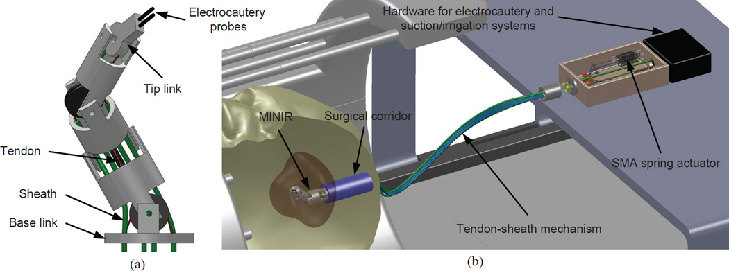
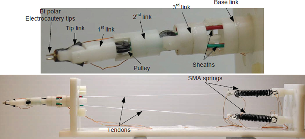
The design of MINIR is shown schematically in Fig. 1(a). The robot consists of a tip link, a base link, and three intermediate cylindrical links, all connected by revolute joints for a total of 4-DOF serial robot. The four revolute joints were placed orthogonally to have out-of-plane motion capability. Each joint has an independent DOF controlled by a pair of antagonistic SMA spring actuators. The SMA actuators are located away from the robot and connected to the robot by tendon-sheath mechanism. Each tendon was routed within a flexible sheath to reach the pulley which is attached to a corresponding joint. The motion range of each joint was designed to be ±60°. The sheaths were more rigid than the tendons and achieved kinematical decoupling of the joint motion. The robot is 63.5 mm long and the largest diameter is 11.5 mm. All components of the robot are made of plastic, except the electrocautery probes that are embedded in the tip link, to ensure its MRI compatibility. The robot body is hollow and allows for suction tubes and electrocautery wiring to be routed inside the robot body.
Figure 1.
The envisioned overall system of MINIR consisting of a 4-DOF robot, tendon-sheath mechanism, an actuation box containing SMA spring actuators, and a hardware box with electrocautery and suction and irrigation hardware.
The overall system of MINIR is shown in Fig. 1(b). The SMA spring actuators were placed 15 cm away from the robot, outside patient’s head, outside the imaging region of the MRI scanner, but inside the MRI bore. This design not only prevents heat damage (if any) or electric shock to brain tissue but also minimizes the image distortion because no electric energy is delivered to patient’s head or imagining region.
3 SMA Spring Modeling
3.1 Modeling of a Single SMA Springs
We propose to use temperature feedback to control the recovery length of SMA springs and hence control the joint motion of MINIR. To use temperature feedback control, we need a model that describes the thermo-mechanical behavior of SMA springs. According to the work of Tanaka et al. (Tobushi & Tanaka 1991) and Liang et al. (Liang & Rogers 1997), the constitutive equation that describes SMA behavior under pure shear conditions can be expressed as:
| (1) |
where τ, G, γ, Ω, ξ, Θ, and T are the shear stress, shear modulus, shear strain, phase transformation coefficient, martensite volume fraction, thermal expansion coefficient, and temperature of the SMA, respectively. Brinson (Brinson 1993) divided the martensite volume fraction into temperature-induced martensite volume fraction, ξt, and stress-induced martensite volume fraction, ξs, where ξ = ξt + ξs. With this definition and assuming that the thermal expansion term is small compared to the other two terms in (1) and thus negligible, the constitutive model of SMAs can be written as:
| (2) |
The phase transformation coefficients, Ωs and Ωt, can be derived from (2) under specific conditions and they can be expressed as (Brinson 1993):
| (3) |
where γL is the maximum recoverable shear strain. Thus, the constitutive model of the SMA in pure shear condition can be written as:
| (4) |
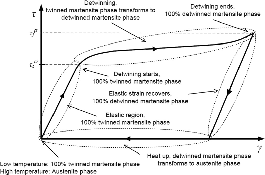
In Brinson’s model, two parameters, and describe the start and end points of stress-induced martensite transformation. is the critical stress for the start of transformation and is the critical stress at the end of transformation. These values are approximated from the shear stress-shear strain curve shown in Fig. 2, where the SMA is initially in 100% undeformed martensite phase.
Figure 2.
Shear stress-shear strain curve of a SMA: The curves show how the shear strain changes with shear stress in a SMA - and are also shown in the figure.
The stress-induced martensite volume fraction during detwinning, i.e., T < Mf, where Mf is the martensite finish temperature of SMA, and , is defined as (Brinson 1993):
| (5) |
When the SMA transforms from martensite phase to austenite phase, i.e., heating transformation, the martensite volume fraction is defined as (Brinson 1993):
| (6) |
where aA and CA are material parameters and As is the austenite start temperature of SMA. In (4), the shear modulus, G, is a function of martensite volume fraction based on Tanaka’s assumption (Tobushi & Tanaka 1991) and it can be expressed as:
| (7) |
where GA and GM are the shear modulus of austenite phase and martensite phase, respectively. For a helical spring, the shear strain and shear stress can be correlated with spring displacement, δ, and spring force, F, respectively. The detailed derivation can be found in most mechanical design textbooks, such as (Shigley & Mischke 2001), and can be expressed as:
| (8) |
where d is the diameter of the spring wire, D is the diameter of the spring, N is the total number of active coils in the spring, and ks is the Wahl correction factor which accounts for both curvature effect and shear stress correction factor. Using (8), (4) can be re-written as:
| (9) |
where δL is the maximum recoverable length and C1 and C2 are constants and defined as:
| (10) |
Equation (9) can be used to describe the force-displacement relationship of a SMA spring.
3.2 Modeling of Antagonistic SMA Springs
Consider two SMA springs with original length L placed antagonistically, pre-stretched by δ0, and then recovered by δr when one of them is heated above the transformation temperature as shown in Fig. 3. For the non-heated SMA spring, there is no temperature induced martensite phase (ξt = 0). Therefore, ξ = ξs since ξ = ξs + ξt. As a result, the thermomechanical relation of the non-heated SMA spring can be obtained from (9) and expressed as:
| (11) |
Based on Brinson’s model (Brinson 1993), when the shear stress in the SMA spring is smaller than , there is no stress induced martensite phase in the SMA (ξs = ξs0 = 0) and hence (11) can be written as:
| (12) |
Therefore, the recovery displacement, δr, can be expressed as:
| (13) |
Equation (13) indicates that the non-heated SMA spring serves as a normal spring with a spring constant, k, given by:
| (14) |
Figure 3.
Illustration of the actuation mechanism of each joint of MINIR, which is used to model the behavior of antagonistic SMA springs.
For the heated SMA spring, it recovered by δr upon heating so that δ−δ0 = −δr. Combining (9) and (13), we get
| (15) |
Since ξ is a cosine function of spring force, F, (15) can be solved numerically when T is known. Equation (15) describes the force-temperature behavior of the heated SMA spring in a pair of antagonistic SMA springs. This equation is used as the governing equation to control the SMA springs using temperature feedback in this paper. To conclude, we can calculate the recovery force, F, in the SMA spring actuator using (15) if temperature, T, is known. We can then use (13) to compute the recovery length of the SMA spring and hence the joint motion of the robot.
4 SMA spring characterization
The goal of this section is to experimentally determine the material constants that are essential for the model that we discussed in section 3. The parameters are dependent on the thermal and mechanical history of the material. Therefore, it is necessary to characterize each SMA spring before using it.
4.1 Characterization of a single SMA spring
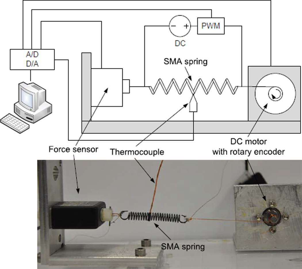
The first part of the characterization was the force-elongation test of a single SMA spring at two different temperatures, i.e., T < As and T > Af, where Af is the austenite finish temperature of the SMA. The goal of this experiment was to determine the shear moduli, critical shear stresses, and maximum recoverable shear strain of the SMA spring. In this experiment, we stretched the SMA spring using the experimental setup shown in Fig. 4. The system consists a DC motor, a force sensor, a thermocouple, a DC power supply, a PWM controller and an AD/DA data acquisition card. The motor is controlled by the PC to stretch the SMA spring to desired lengths. The rotary encoder is used for position measurements and the force sensor is used to measure the recovery force generated by the spring. The thermocouple used to measure the spring temperature is attached at the center of the spring. DC power supply and resistive heating was used to heat up the SMA spring, and the PWM controller was used to control the temperature in the SMA spring. The entire experimental setup except the PC was put inside a chamber to ensure stable measurements of temperature. The experimental results are shown in Fig. 5.
Figure 4.
Experimental setup for the force-elongation test of a SMA spring.
Figure 5.
Experimental results of the force-elongation test of a SMA spring at two different temperatures (six experiments were conducted for each data point).
From the experimental results when T < As, the spring constant, k, can be determined from the linear region of the curve and the martensite shear modulus, GM, can then be computed using (14). The austenite shear modulus, GA, can be determined using the same approach based on the experimental results when T > Af. The critical shear stress, , was determined by finding the maximum force of the linear region of the curve when T < As and then computed using (10). Another critical stress, , and the maximum recoverable shear strain, γL, was approximated by fitting the experimental curve when T < As using (5) and (11). The theoretical curves in Fig. 5 were computed using (5), (6), (9) and (11) with the material parameters listed in Table I.
Table 1.
Material parameters determined experimentally
| Shear moduli |
Transformation temperatures |
Critical shear stresses |
Maximum recoverable shear strain |
Spring parameters |
|---|---|---|---|---|
| GM = 15.12 GPa | As = 28 °C | = 120 MPa | γL = 0.05 | D = 6.223 mm |
| GA = 31.84 GPa | Af = 39 °C | = 290 MPa | d = 0.763 mm | |
| N = 22 |
From the results, we also found that when the elongation of the SMA spring was less than 25 mm, the SMA spring behaved like a normal spring and it fully recovered when released after stretching. Since we plan to use the non-heated SMA spring as a bias spring in the antagonistic setup, the initial stretch, δ0, of the SMA spring should be less than 12.5 mm to ensure its full recovery when released. Therefore, the initial stretch of the SMA springs was set to 12 mm in all the experiments.
In the second part of the characterization process, we conducted free recovery tests to find the transformation temperatures of the SMA spring. The experimental setup was similar to the one that we used for the previous experiment but the DC motor was replaced with a rotary encoder. The SMA spring was stretched by 12 mm before the experiment started. During the experiment, the SMA spring was heated to the desired temperatures and the recovered length of the SMA spring were recorded. The SMA spring started to recover when the temperature was higher than the austenite start temperature, As, and recovered to its original length when the temperature was higher than the austenite finish temperature, Af. The experimental results are shown in Fig. 6 and the transformation temperatures, As and Af, were determined to be 28 °C and 39 °C respectively. The theoretical model in the figure was computed using (6) and (9) with the parameters listed in table I.
Figure 6.
Experimental results of the free recovery test of a SMA spring, which shows how recovery length of the SMA changes with its temperature. There are tens sets of test in the experiment.
4.2 Characterization of Antagonistic SMA springs
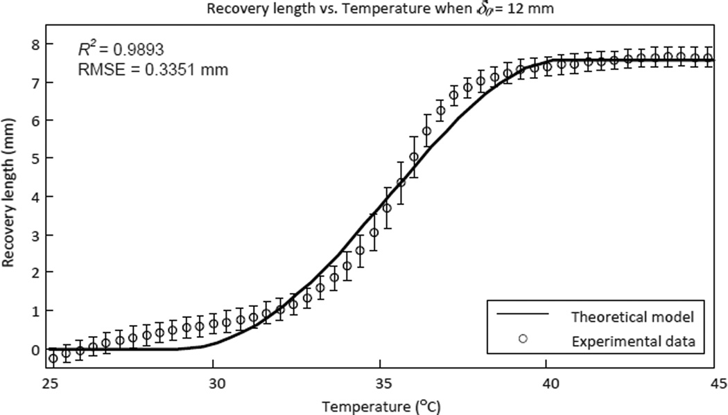
After obtaining all necessary material parameters of the SMA spring, we need to further verify the validity of the antagonistic model that was developed in section 3.2. The experimental setup is shown in Fig. 7 and the experimental results are shown in Fig. 8. The theoretical model in the figure was computed using (15) with the material parameters listed in table I.
Figure 7.
Experimental setup to characterize the behavior of the antagonitic SMA springs.
Figure 8.
Experimental results of the antagonistic SMA springs chracterization, which shows how the recovery length of the controlled/heated SMA spring changes with temperature in the antagonistic setup (ten experiments were conducted for each data point).
The experimental results fit the theoretical model well with a coefficient of determination (R2) of 0.9893 and a root-mean-square error (RMSE) of 0.3351 mm, which proves that the recovery length of the actuated SMA spring can be computed using (15) if the temperature in the actuated SMA spring is known. In other words, we can control the length of the SMA spring using temperature feedback and hence control the joint motion of the robot. The SMA spring recovered by 8 mm when heated to 40 °C while the initial elongation was 12 mm. The maximum motion range of each MINIR joint was designed to be ±60°. Since the diameter of the pulley used in the robot is 7 mm, recovery length of 8 mm in the SMA spring was sufficient to move the robot joint to its maximum joint angle limit.
5 Experimental Results
5.1 Motion Test
The overall system of MINIR with SMA spring actuators is shown in Fig. 9. The robot was 63.5 mm long and the maximum diameter was 11.5 mm. The goal of this experiment was to evaluate if the tendon-sheath mechanism and the SMA spring actuators could be used to actuate various joints of MINIR to move in orthogonal directions and if each joint can be independently controlled. Therefore, we only used four SMA springs to actuate two joints of MINIR. During the experiment, we actuated the 1st link and the 2nd link individually from their neutral positions to respective joint limits to show that the two joints of MINIR can be independently controlled. The results are shown in Fig. 10 and a video of the robot motion can be found in Extension 1.
Figure 9.
Current prototype of MINIR with SMA springs connected to the robot through the tendon-sheath mechanism.
Figure 10.
Two different configurations of MINIR after actuation demonstrating clockwise and counterclockwise motion capability.
5.2 Force Test
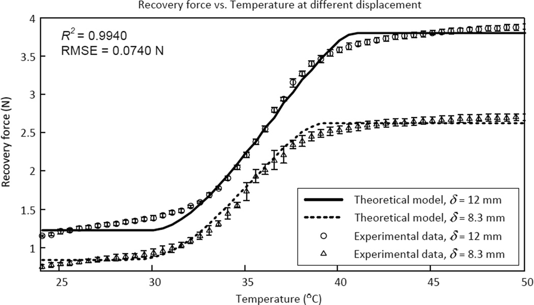
The goal of this experiment was to measure the output force of the antagonistic SMA springs at different spring elongation and therefore estimate the joint torque of MINIR at different bending angles. The experimental setup is shown in Fig. 7 and one of the SMA spring was stretched to 12 mm and 8.3 mm, respectively for two different sets of experiments before being attached to the experimental setup. When the SMA spring was stretched to 12 mm, the bending angle of the MINIR joint was set to 0°. Similarly, when the SMA spring was stretched to 8.3 mm, the bending angle of the MINIR was set to 60°. This helped us understand the range of the output force over the range of motion for each MINIR joint. The SMA spring was then heated to specific temperatures while the corresponding force readings were recorded. The experimental results are shown in Fig. 11 and fits the theoretical model well (R2 = 0.9948 and RMSE = 0.0740 N). In the figure, we observe that the SMA spring could generate up to 3.9 N and 2.5 N of force when the SMA spring was stretched to 12 mm and 8.3 mm respectively. Thus we can conclude that the MINIR joint could generate 17.5 N-mm to 27.3 N-mm of torque depending on the spring contraction from the initial stretched configuration.
Figure 11.
Experimental results of the recovery force of a SMA spring at different temperatures with two different initial elongation. The figure shows how the recovery force in a SMA spring changes with temperature and initial elongation of the spring (six experiments were conducted for each data point).
5.3 Test in Gelatin
To ensure that the SMA spring can generate sufficient force to move the robot in a tightly enclosed environment, we tested the robot in a gelatin slab. The gelatin slab (Knox, USA) was used to simulate brain tissue. Using one dimensional indentation device, we carried out indentation experiments to estimate the mechanical property of the gelatin. Reaction forces against 3 mm indentation were measured by a force sensor (MLP-10, Transducer Techniques, USA) and collected by the Arduino board. The mechanical property (E, Youngs modulus) of the gelatin was estimated by the experimental results and the Hertz-Sneddon equation to be approximately 17.56 kPa. The electrocautery and suction systems were also integrated in the robot and tested in the experiment to ensure that they were functioning as expected. The experimental results are shown in Fig. 12. The robot was inserted into the gelatin and the first link was actuated to move back and forth. Each SMA actuator was actuated with 0.5 A of current and 50 % duty cycle of the PWM controller individually. The cycling time of the PWM controller was 2 seconds. The electrocautery and suction systems were also activated when the robot was moving. Experimental results demonstrated that the robot could move in gelatin and the electrocautery and suction systems were able to electrocauterize the gelatin and suck the melted gelatin out (see Extension 2 for a video demonstration).
Figure 12.
Motion of MINIR in gelatin - This demonstrates that MINIR has sufficient joint torque to move in the gelatin medium and achieve the desired range of motion.
5.4 MRI Compatibility Test
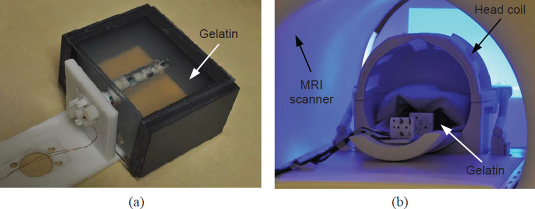
Since MINIR was desired to be operated in MRI scanners, we did a series of experiments to evaluate the MRI compatibility of MINIR. The experimental setup is shown in Fig. 13. We used gelatin to simulate brain tissue and the robot was inserted into the gelatin slab through a channel that was created in advance as seen in Fig. 13(a). The robot and gelatin were then placed in a head coil at the center of a MRI scanner as shown in Fig. 13(b). The same experimental setup was used throughout the series of experiments in this section.
Figure 13.
Experimental setup for MRI compatibility test of MINIR: (a) MINIR is inserted in a gelatin slab and (b) MINIR with the gelatin is put in a head coil and placed at the iso-center of the MRI scanner.
We then connected all required connections to MINIR and turned on all the devices connected to it. A high resolution scan was performed and the MR images are shown in Fig. 14. The figure shows the MR images of three different slices in the gelatin and each slice was 2 mm apart. The robot profile can be clearly seen and there was minimal distortion in the images.
Figure 14.
High resolution MR images of MINIR in gelatin before actuation: (a) top slice, (b) middle slice, and (c) bottom slice. The images show that MINIR does not create significant image distortion in the MRI scanner.
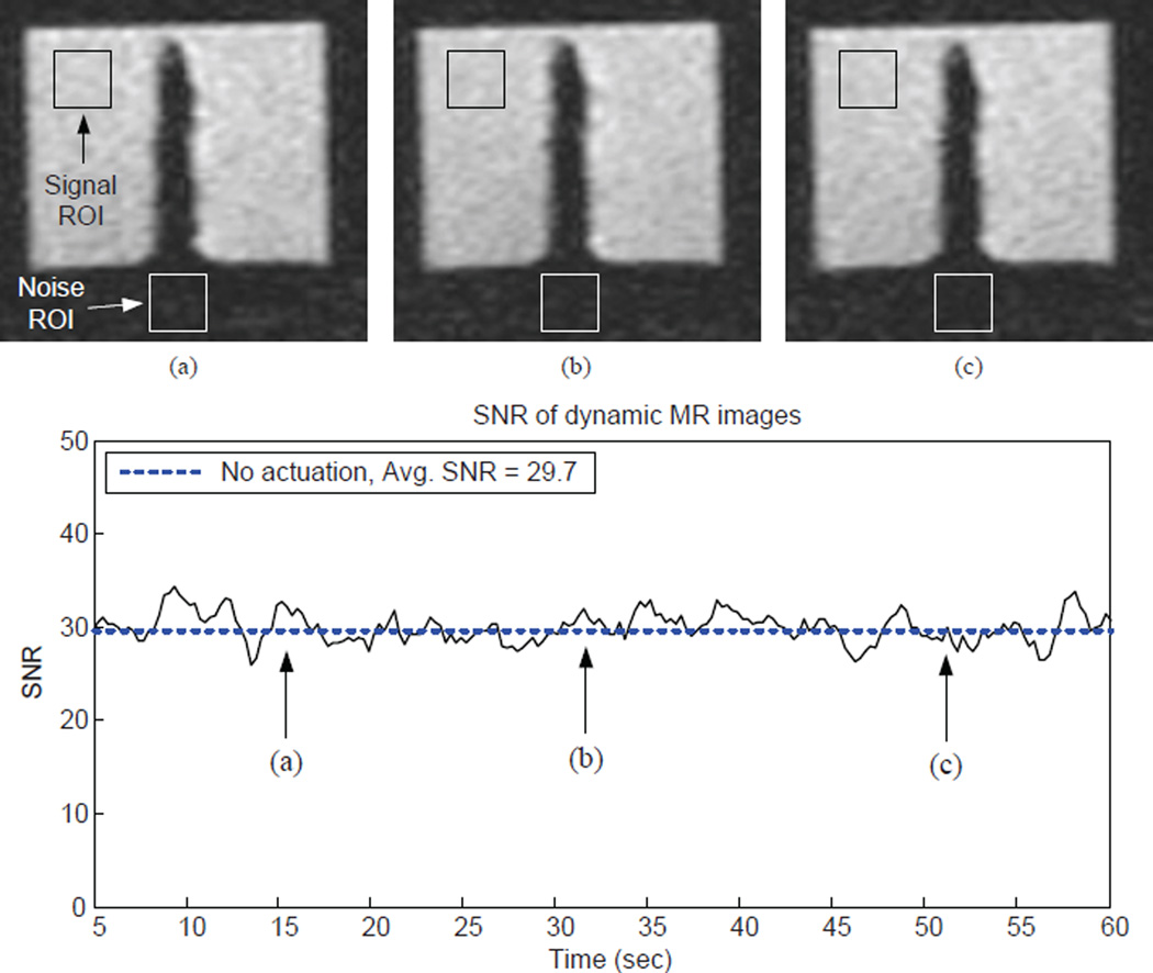
A dynamic scanning sequence was then used to continuously take 200 images in 60 seconds. This experiment was used to qualitatively evaluate if there is any image distortion caused by the robot as well as quantitatively see how the signal-to-noise ratio (SNR) changes during scanning. The experimental results in this step were used as the ground truth for comparison with the MR images obtained later. Three dynamic MR images at three different time points and the SNR of each image is shown in Fig. 15. The MR images did not show any distortion and the SNR did not change significantly during scanning. The average SNR of the 200 images was 29.7.
Figure 15.
Dynamic MR images of the non-actuated MINIR at three different time points and the SNR of each image. We collected a total of 200 images in the experiment. The results serve as ground truth for comparison with later experiments when MINIR is actuated during imagining.
In the next scan, we actuated the robot and started electrocauterization while taking dynamic images to evaluate the influence of the actuation of the SMA springs and the electrocauterization in the MR images. During the experiment, we actuated the first link to the right and then moved the second link up. After actuation, we started to electrocauterize the gelatin. The experimental results are shown in Fig. 16. The images show that MINIR was successfully actuated and the electrocautery system successfully melted the gelatin creating a void in the gelatin [see Fig. 16(c)]. The SNR of each image is also shown in the figure, and the SNR dropped by 0.7% during actuation, i.e., the SNR dropped from 27.6 to 27.4 and 1.4% during electrocauterization, i.e., the SNR dropped from 27.6 to 27.2. The results confirm that the actuation of MINIR does not affect the image quality and also shows that the electrocauterization does not cause significant noise in the MR images.
Figure 16.
Dynamic MR images of MINIR at three different time points: (a) MINIR is not actuated, (b) the tip link of MINIR is moved to right, (c) electrocautery is activated and creating a void in the gelatin; the SNR of each image is correspondingly shown in the graph for all the 200 images. The results show that the actuation of SMA actuators and electrocautery do not create significant noise to the images.
A high resolution scan was then performed to show that MINIR worked as expected. The images in Fig. 17 clearly show that the first link of MINIR has been moved to the right and the second link was moved up because the links can only be seen in the upper layers of the gelatin. The void in the gelatin created by electrocauterization is also seen in the figure.
Figure 17.
High resolution MR images of MINIR in gelatin after actuation: (a) top slice, (b) middle slice, and (c) bottom slice. The images clearly show that the tip link of MINIR is moved to right and a void in gelatin is careated after electrocauterization.
From the above results, we confirmed that the MINIR system was MRI compatible and the effect of the current to actuate SMA spring actuators and the electrocautery probes was not significant after a series of experiment in this section. Therefore, we can conclude that MRI can be used to provide continuous visual feedback for physicians while performing brain tumor resection using MINIR. With continuous visual feedback, physicians can remove the brain tumor completely and precisely while minimizing trauma to the surrounding healthy brain during intracranial procedures.
5.5 Ex-Vivo Test
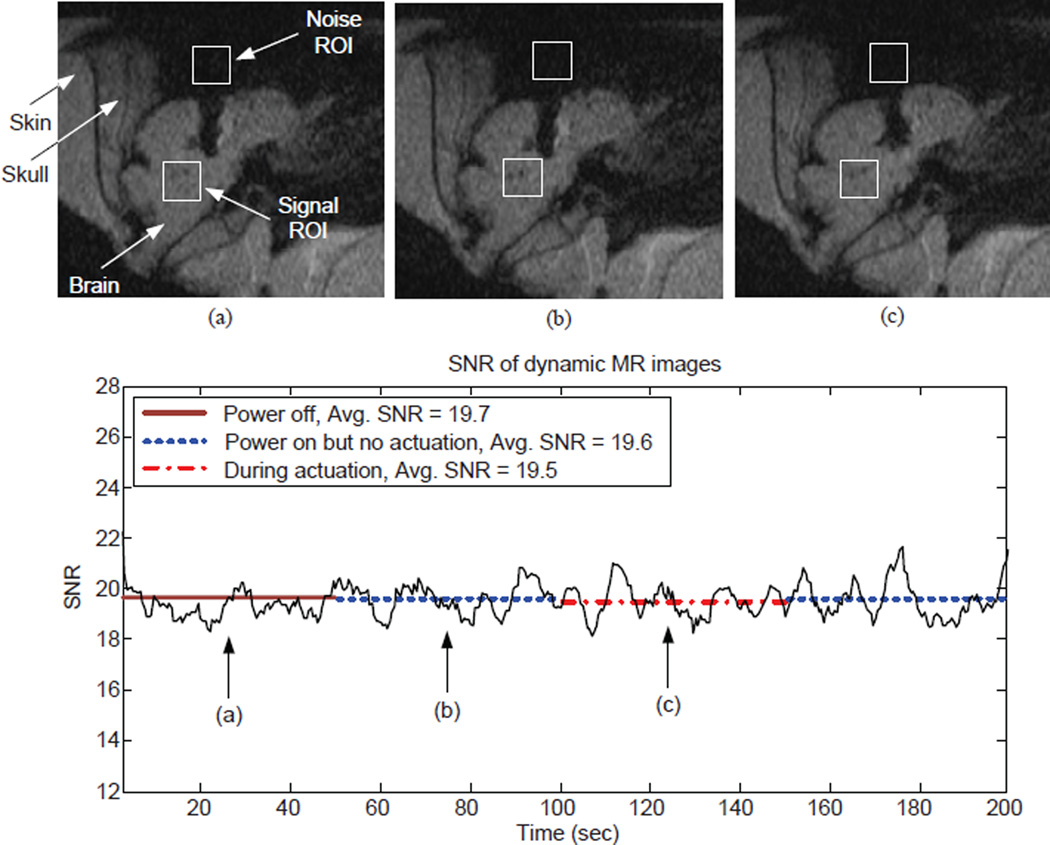
After testing MINIR in gelatin, we further tested it ex vivo in a pig brain. MINIR was covered with a layer of plastic sheath to isolate it from tissue, blood, and other liquid in the brain as shown in Fig. 18(a). Figure 18(b) shows MINIR inserted in a pig brain through an opening on the skull. The thickness of the skin and skull was approximately 40 mm, however, MINIR was only 63.5 mm long. Therefore, only the tip link and the first link of MINIR could be inserted inside the brain and only the first link of MINIR was actuated in this experiment. 400 MR images were taken continuously during the 200 seconds scanning period. All devices were off in the first 50 seconds and then turned on for 50 seconds. After that, MINIR was actuated to move to the right for 50 seconds and then stopped for the remaining 50 seconds. The MR images at three different time points are shown in Fig. 19. The images show no observable changes for the first 100 seconds [see Figs. 19(a) and (b)] and MINIR was moved to right during actuation [see Fig. 19(c)]. The SNR of each image is also shown in the figure and there is no significant change in the three different conditions. The SNR only dropped by 0.5%, i.e., the SNR dropped from 19.7 to 19.6 after turning on the power of all devices and the SNR dropped by 0.5% from 19.6 to 19.5 during actuation. The results indicate that the noise caused by turning on the power of all devices and passing electric current through the SMA spring actuators was very small.
Figure 18.
Experimental setup for ex vivo test: (a) MINIR covered with a plastic sheath and only electrocautery probes are outside and (b) MINIR inside a pig brain.
Figure 19.
Dynamic MR images at three different time points when MINIR is operating in the brain: (a) all devices powered OFF, (b) all devices powered ON but no actuation, and (c) the tip link of MINIR is moved to the right. There are a total of 400 images in the experiment. The results show that the actuation of SMA actuators and electrocautery does not create significant noise in the images.
5.6 Image Feedback Control
We have shown that the MR images of MINIR were clear without significant image distortion in sections 5.4 and 5.5. Therefore, we expect MINIR to be controlled using continuous MR images as feedback. In this section, we present the experimental results of using image feedback to control the joint motion of MINIR. Since we are not currently using MR images directly at this point to guide the motion of MINIR, we used a camera to get the images of MINIR and used the image-feedback from the camera to guide the motion of MINIR. The experimental setup is shown in Fig. 20 and we assumed that the image plane was parallel to the motion plane.
Figure 20.
Experimental setup for image feedback and temperature feedback motion control tests of MINIR.
The color depth and frame rate of the camera was set to 8-bit gray scale and 4 fps, respectively, which was close to the image quality of a dynamic MR scan image. The 4 fps frame rate was fast enough for MINIR because the response of SMA springs was slow. We used Lucas-Kanade Optical Flow Method (Lucas & Kanade 1981) to track the coordinates of the electrocautery probes and the tracking images are shown in Fig. 21. The images simulated MINIR operating in a medium that contained water so that the background of the image was white which is the color of water in MR images and MINIR was black because of its plastic body. The track point was selected manually and the tracking algorithm found the best feature to track in the nearby areas. The target point could be selected manually from the image and a PWM-PI controller was used to heat the corresponding SMA spring actuator until the track point reached the target point.
Figure 21.
Image feedback motion control of MINIR. The images show the tip of MINIR is controlled to move towards the target point.
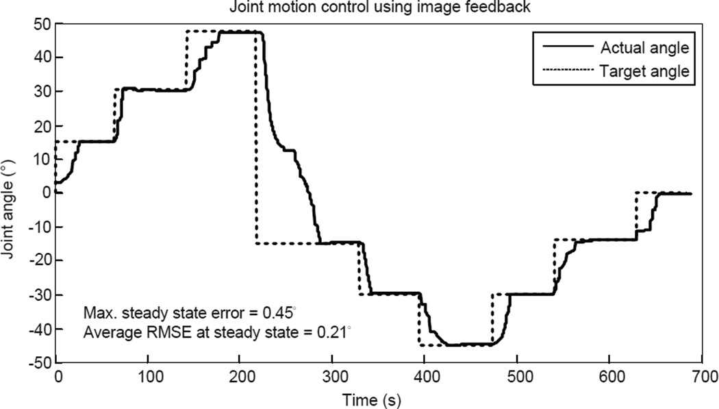
The experimental results are shown in Fig. 22 with a maximum error of 0.45° and an average RMS error of 0.21° at steady state. It is important to note that when the motion direction changes, the heated SMA spring must be cooled down below As before the other SMA spring can be actuated. If the other SMA spring is heated right away, both SMA springs will be at a higher temperature and the heated SMA spring actuator might not be able to reach the target location, which could potentially result in over-heating. Therefore, monitoring the temperature in each SMA spring actuator is required in the antagonistic setup.
Figure 22.
Experimental results of the image feedback motion control of MINIR.
We also performed the image feedback control for MINIR in the gelatin slab. The experimental setup is shown in Fig. 23 (a) and we assumed again that the image plane was parallel to the motion plane. The robot was actuated by heating with 2 A current and cooling with a fan. Fig. 23 (b) shows that MINIR was able to follow the commanded step inputs in the gelatin environment as well.
Figure 23.
(a) Experimental setup of image feedback control of MINIR in gelatin (b) Experimental results of the image feedback motion control of MINIR in gelatin.
5.7 Temperature Feedback Control
The image feedback control may fail due to noise in the images or missing the track point and therefore a backup controller is required for MINIR. In the previous section 5.6, we discussed the necessity to monitor the temperature in each SMA spring. Since the temperature information is available, it is natural to use temperature feedback as the backup control strategy. The experimental setup for temperature feedback control is the same as Fig. 20, but we only relied on temperature to control the joint motion of MINIR.
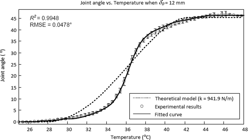
Experimental results indicated that the temperature controller based on the theoretical model does not perfectly match the experimental data as seen in Fig. 24. This is partly because we have currently not incorporated the nonlinear properties such as backlash, hysteresis and friction in the tendon-sheath model. The nonlinear characteristics of tendon-sheath mechanisms have been discussed and modeled extensively (Agrawal et al. 2010, Chen et al. 2013) and they can be compensated using feedforward terms, such as in (Palli et al. 2012). We have currently not modeled the nonlinear characteristics of the tendon-sheath mechanism used in MINIR, but we believe that the antagonistic SMA spring model will be valid to control the joint motion of MINIR if the nonlinear characteristics of the tendon-sheath mechanism are incorporated into the model.
Figure 24.
Experimental results of the joint angle at different temperatures and how it differs from the theoretical model with empirical stiffness of the joint (ten experiments were conducted for each data point).
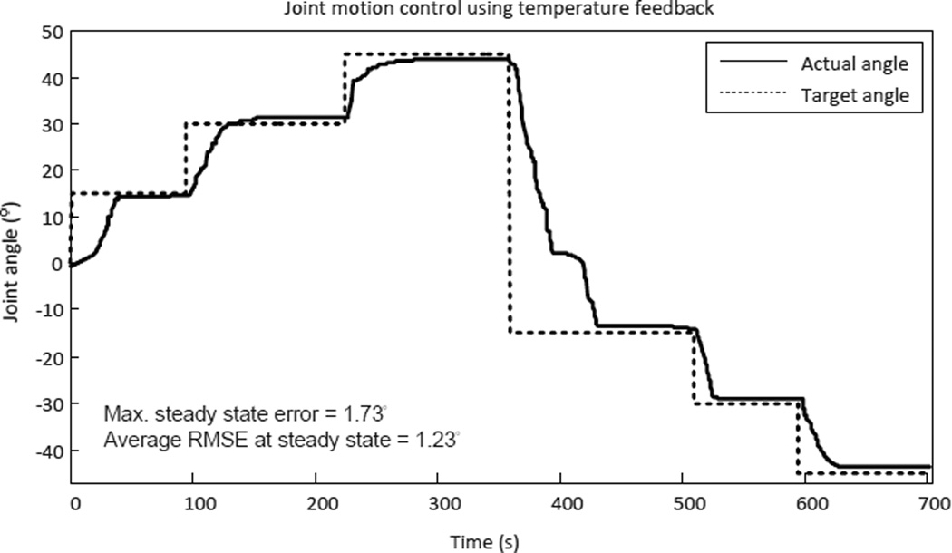
The experimental results of joint motion vs. temperature tests are shown in Fig. 24. The results were repeatable and the fitted curve can be used as an empirical model (R2 = 0.9980 and RMSE = 0.0478°). At this point, we decided to use the empirical model to control the robot. During the control experiments, the desired joint angle was converted to temperature command, T, through the empirical model and then sent to the PWM-PI temperature controller and the control results are shown in Fig. 25.
Figure 25.
Experimental results of temperature feedback motion control of MINIR.
In this experiment, the SMA spring #1 was used to move the joint to positive joint angle while the SMA spring #2 was used to move the joint to negative joint angle. The experimental results show that the temperature feedback motion control worked well with a maximum error of 1.73° and an average RMS error of 1.23° at steady state. It is important to note that when the robot was commanded to change the motion direction, the heated SMA spring had to be cooled below As before the other SMA spring could be actuated. We observed that when the control command changed from 45° to −15°, SMA #1 was cooled to 26°C before SMA #2 was heated.
6 Conclusion
In this paper, we presented a new design of MINIR actuated by SMA spring actuators and the tendon-sheath mechanism. The prototype has lager range of motion, larger output force, and better MRI compatibility compared to our previous work (Ho et al. 2012).
We modeled and characterized the behavior of a single SMA spring actuator as well as antagonistic SMA springs. The models derived from the constitutive equation of SMAs can be used to describe the relationship between the recovery length and the temperature of an SMA spring. We also experimentally determined material parameters that are required for the theoretical models. We proposed to use these models to develop a temperature feedback control algorithm to control the recovery length of the antagonistic SMA springs and hence control the joint motion of MINIR. However, the theoretical model did not fit the experimental data well due to the hysteresis in the cabling. Therefore, we used an empirical model to control the robot instead of using the theoretical model. The maximum positioning error of MINIR when using temperature feedback control was 3°.
We also demonstrated that MINIR is MRI compatible by actuating the robot inside a MRI scanner while taking continuous MR images. The images showed no significant distortion and very limited SNR drop was observed. Thus, the current design of MINIR enables the possibility of using MR images as visual feedback for physicians when performing a deep brain tumor resection. We also implemented an image feedback controller to control the joint motion of MINIR. The maximum positioning error was less than 1° when the image feedback controller was used. Since both image feedback and temperature feedback can be used to control the joint motion of MINIR, temperature feedback can be used as a backup control scheme for MINIR in case the image tracking algorithm fails.
We noticed that the actuation speed was slow due to the slow cooling nature of SMA material in antagonistic configuration. Higher current without overheating and active cooling could have been used to speed up the actuation process but the robot was not required at such speed during an electrocauterization procedure. We recognize the importance to improve the actuation bandwidth of the robot to meet higher speed demand in certain procedures. However, in this paper, we intended to focus on introducing the robot design, antagonistic SMA modeling, its MRI-compatibility, ex-vivo testing and feedback control. Therefore, active cooling is beyond the scope of this paper and will be addressed in future work.
Acknowledgements
Research reported in this publication was supported by the National Institute Of Biomedical Imaging And Bioengineering of the National Institutes of Health under Award Number R01EB015870. The content is solely the responsibility of the authors and does not necessarily represent the official views of the National Institutes of Health.
Appendix A: Index to Multimedia Extensions
| Extension | Media Type | Description |
|---|---|---|
| 1 | Video | Demonstrate the motion of MINIR in air |
| 2 | Video | Demonstrate the motion of MINIR in gelatin and the effectiveness of the integrated electrcautery probes and the suction tube |
References
- Agrawal V, Peine WJ, Yao B. Modeling of transmission characteristics across a cable-conduit system. IEEE Transactions on Robotics. 2010;26(5):914–924. [Google Scholar]
- Ayvali E, Liang C-P, Ho M, Chen Y, Desai JP. Towards a discretely actuated steerable cannula for diagnostic and therapeutic procedures. International Journal of Robotics Research. 2012;31(5):588–603. doi: 10.1177/0278364912442429. [DOI] [PMC free article] [PubMed] [Google Scholar]
- Benabid A, Cinquin P, Lavalle S, Le Bas J, Demongeot J, de Rougemont J. Computer-driven robot for stereotactic surgery connected to CT scan and magnetic resonance imaging. Appl Neurophysiol. 1987;50:153–154. doi: 10.1159/000100701. [DOI] [PubMed] [Google Scholar]
- Bone G, Ning S. Experimental comparison of position tracking control algorithms for pneumatic cylinder actuators. IEEE/ASME Transactions on Mechatronics. 2007;12(5):557–561. [Google Scholar]
- Brinson LC. One-dimensional constitutive behavior of shape memory alloys: Thermo-mechanical derivation with non-constant material functions and redefined martensite internal variable. Journal of Intelligent Material Systems and Structures. 1993;4(2):229–242. [Google Scholar]
- Bundhoo V, Haslam E, Birch B, Park EJ. A shape memory alloy-based tendon-driven actuation system for biomimetic artificial fingers, part I: Design and evaluation. Robotica. 2009;27:131–146. [Google Scholar]
- Chen L, Wang X, Xu W. Inverse transmission model and compensation control of a single-tendon-sheath actuator. IEEE Transactions on Industrial Electronics. 2013 [Google Scholar]
- Ho M, Desai JP. Modeling, characterization and control of antagonistic SMA springs for use in a neurosurgical robot; Proceedings of the IEEE International Conference on Robotics and Automation; 2013. pp. 2488–2493. [Google Scholar]
- Ho M, Koltz M, Simard JM, Gullapalli R, Desai JP. Towards a MR image-guided SMA-actuated neurosurgical robot; Proceedings of the IEEE International Conference on Robotics and Automation; 2011. pp. 1153–1158. [Google Scholar]
- Ho M, McMillan AB, Simard JM, Gullapalli R, Desai JP. Toward a mesoscale SMA-actuated MRI-compatible neurosurgical robot. IEEE Transactions on Robotics. 2012;28(1):213–222. doi: 10.1109/TRO.2011.2165371. [DOI] [PMC free article] [PubMed] [Google Scholar]
- Holton A, Walsh E, Anayiotos A, Pohost G, Venugopalan R. Comparative MRI compatibility of 316L stainless steel alloy and nickel-titanium alloy stents. Journal of Cardiovascular Magnetic Resonance. 2002;4(4):423–430. doi: 10.1081/jcmr-120016381. [DOI] [PubMed] [Google Scholar]
- Hongo K, Goto T, Kakizawa Y, ichi Koyama J, Kawai T, Kan K, Tanaka Y, Kobayashi S. Micromanipulator system (NeuRobot): clinical application in neurosurgery. Proceedings of the 17th International Congress and Exhibition on Computer Assisted Radiology and Surgery. 2003;1256:509–513. [Google Scholar]
- Ikuta K, Tsukumoto M, Hirose S. Shape memory alloy servo actuator system with electric resistance feedback and application for active endoscope; Proceedings of the IEEE International Conference on Robotics and Automation; 1988. pp. 427–430. [Google Scholar]
- Izawa J, Shimizu T, Aodai T, Kondo T, Gomi H, Toyama S, Ito K. Mr compatible manipulandum with ultrasonic motor for fMRI studies; Proceedings of the IEEE International Conference on Robotics and Automation; 2006. pp. 3850–3854. [Google Scholar]
- Kim D, Kobayashi E, Dohi T, Sakuma I. A new, compact MR-compatible surgical manipulator for minimally invasive liver surgery; Proceedings of the International Conference on Medical Image Computing and Computer-Assisted Intervention; 2002. pp. 99–106. [Google Scholar]
- Kokes R, Lister K, Gullapalli R, Zhang B, MacMillan A, Richard H, Desai JP. Towards a teleoperated needle driver robot with haptic feedback for RFA of breast tumors under continuous MRI. Medical Image Analysis. 2009;13(3):445–455. doi: 10.1016/j.media.2009.02.001. [DOI] [PMC free article] [PubMed] [Google Scholar]
- Liang C, Rogers CA. Design of shape memory alloy springs with applications in vibration control. Journal of Intelligent Material Systems and Structures. 1997;8(4):314–322. [Google Scholar]
- Lucas BD, Kanade T. An iterative image registration technique with an application to stereo vision; Proceedings of the international joint conference on Artificial intelligence; 1981. pp. 674–679. [Google Scholar]
- Masamune K, Kobayashi E, Masutani Y, Suzuki M, Dohi T, Iseki H, Takakura K. Development of an MRI-compatible needle insertion manipulator for stereotactic neurosurgery. Journal of Image Guided Surgery. 1995;1(4):242–248. doi: 10.1002/(SICI)1522-712X(1995)1:4<242::AID-IGS7>3.0.CO;2-A. [DOI] [PubMed] [Google Scholar]
- McBeth PB, Louw DF, Rizun PR, Sutherland GR. Robotics in neurosurgery. The American Journal of Surgery. 2004;18(4) Supplement 1:68–75. doi: 10.1016/j.amjsurg.2004.08.004. [DOI] [PubMed] [Google Scholar]
- Nakamura Y, Matsui A, Saito T, Yoshimoto K. Shape-memory-alloy active forceps for laparoscopic surgery; Proceedings of the IEEE International Conference on Robotics and Automation; 1995. pp. 2320–2327. [Google Scholar]
- Oura M, Kobayashi Y, Okamoto J, Fujie M. Development of MRI compatible versatile manipulator for minimally invasive surgery; Proceedings of the IEEE International Conference on Biomedical Robotics and Biomechatronics; 2006. pp. 176–181. [Google Scholar]
- Palli G, Borghesan G, Melchiorri C. Modeling, identification, and control of tendon-based actuation systems. IEEE Transactions on Robotics. 2012;28(2):277–290. [Google Scholar]
- Patriciu A, Petrisor D, Muntener M, Mazilu D, Schar M, Stoianovici D. Automatic brachytherapy seed placement under MRI guidance. IEEE Transactions on Biomedical Engineering. 2007;54(8):1499–1506. doi: 10.1109/TBME.2007.900816. [DOI] [PMC free article] [PubMed] [Google Scholar]
- Shigley JE, Mischke CR. Mechanical Engineering Design. McGraw Hill: 2001. [Google Scholar]
- Stoianovici D, Patriciu A, Petrisor D, Mazilu D, Kavoussi L. A new type of motor: Pneumatic step motor. IEEE/ASME Transactions on Mechatronics. 2007;12(1):98–106. doi: 10.1109/TMECH.2006.886258. [DOI] [PMC free article] [PubMed] [Google Scholar]
- Sutherland GR, McBeth PB, Louw DF. Neuroarm: an mr compatible robot for microsurgery. Proceedings of the 17th International Congress and Exhibition on Computer Assisted Radiology and Surgery. 2003;1256:504–508. [Google Scholar]
- Takasuna H, Goto T, Kakizawa Y, Miyahara T, Koyama J, Tanaka Y, Kawai T, Hongo K. Use of a micromanipulator system (neurobot) in endoscopic neurosurgery. Journal of Clinical Neuroscience. 2012;19:1553–1557. doi: 10.1016/j.jocn.2012.01.033. [DOI] [PubMed] [Google Scholar]
- Teh YH, Featherstone R. An architecture for fast and accurate control of shape memory alloy actuators. International Journal of Robotics Research. 2008;27(5):595–611. [Google Scholar]
- Tobushi H, Tanaka K. Deformation of a shape memory alloy helical spring : Analysis based on stress-strain-temperature relation. JSME international journal. Ser. 1, Solid mechanics, strength of materials. 1991;34-I(1):83–89. [Google Scholar]
- Yang B, Tan U-X, McMillan AB, Gullapalli R, Desai JP. Design and control of a 1-DOF MRI-compatible pneumatically actuated robot with long transmission lines. IEEE/ASME Transactions on Mechatronics. 2011a;16:1040–1048. doi: 10.1109/TMECH.2010.2071393. [DOI] [PMC free article] [PubMed] [Google Scholar]
- Yang B, Tan U-X, McMillan A, Gullapalli R, Desai JP. Design and implementation of a pneumatically-actuated robot for breast biopsy under continuous MRI; Proceedings of the IEEE International Conference on Robotics and Automation; 2011b. pp. 674–679. [Google Scholar]
- Yu N, Hollnagel C, Blickenstorfer A, Kollias S, Riener R. Comparison of MRI-compatible mechatronic systems with hydrodynamic and pneumatic actuation. IEEE/ASME Transactions on Mechatronics. 2008;13(3):268–277. [Google Scholar]


