Abstract
The effects of alveolar bone socket geometry and bone-implant contact on implant biomechanics, and resulting strain distributions in bone were investigated. Following extraction of lateral incisors on a cadaver mandible, immediate implants were placed and bone-implant contact area, stability and bone strain were measured. In situ biomechanical testing coupled with micro X-ray microscope (μ-XRM) illustrated less stiff bone-implant complexes (701-822 N/mm) compared with bone-periodontal ligament (PDL)-tooth complexes (791-913 N/mm). X-ray tomograms illustrated that the cause of reduced stiffness was due to reduced and limited bone-implant contact. Heterogeneous elemental composition of bone was identified by using energy dispersive X-ray spectroscopy (EDS). The novel aspect of this study was the application of a new experimental mechanics method, that is, digital volume correlation, which allowed mapping of strains in volumes of alveolar bone in contact with a loaded implant. The identified surface and subsurface strain concentrations were a manifestation of load transferred to bone through bone-implant contact based on bone-implant geometry, quality of bone, implant placement, and implant design. 3D strain mapping indicated that strain concentrations are not exclusive to the bone-implant contact regions, but also extend into bone not directly in contact with the implant. The implications of the observed strain concentrations are discussed in the context of mechanobiology. Although a plausible explanation of surgical complications for immediate implant treatment is provided, extrapolation of results is only warranted by future systematic studies on more cadaver specimens and/or in vivo small scale animal models.
Keywords: implant, bone-implant contact, strain, digital volume correlation, alveolar bone
1 Introduction
In a bone-periodontal ligament (PDL)-tooth fibrous joint, the alveolar bone adapts in response to functional loads on teeth (Ten Cate, 1998; Weinmann and Sicher, 1955; Weinmann, 1941). Alveolar bone continuously adapts through a cascade of mechanobiological events until optimal peak strain levels are restored (Eugene Roberts et al., 2004). When a tooth is replaced with an implant, strain distribution within the alveolar bone can change (Brunski, 1999; Greenstein et al., 2013; Wazen et al., 2013). From a biomechanics and a mechanobiology perspective, the load-induced mechanical strain in alveolar bone from immediately loaded implants is poorly understood but clinically relevant.
From a clinical perspective, the biomechanical behavior of implants is often characterized by measuring implant stability using percussion tests, periotest (Choi et al., 2014; Olivé and Aparicio, 1990), torque test (installation torque and removal torque) (O'Sullivan et al., 2000; Wennerberg et al., 1995) or by performing resonance frequency analysis (Choi et al., 2014; Monje et al., 2014; O'Sullivan et al., 2000; Ostman et al., 2006). In laboratory, mechanical strains in bone-teeth and bone-implant complexes have been investigated using several methods including strain gauges (Akça et al., 2007; Asundi and Kishen, 2000a; Jantarat et al., 2001; Popowics et al., 2004), photoelasticity (Asundi and Kishen, 2001, 2000b), Moiré interferometry (Kishen et al., 2006; Wang and Weiner, 1998; Wood et al., 2003), electronic speckle pattern interferometry (ESPI) (Zaslansky et al., 2006, 2005), finite element method (Baggi et al., 2008; Bozkaya et al., 2004; Van Oosterwyck et al., 1998; Wazen et al., 2013) and digital image correlation (DIC) (Qian et al., 2009; Tiossi et al., 2011; Zhang et al., 2009). Digital volume correlation (DVC) has been used to map strains in trabecular bone, without teeth or an implant (Bay et al., 1999; Jiroušek et al., 2011; Verhulp et al., 2004; Zauel et al., 2006).
Biomechanics of the bone-implant complex, including mechanical strain is influenced by numerous factors including socket geometry and bone-implant contact. The purpose of this study was to investigate the biomechanics of two bone-implant complexes where implants were immediately loaded following implant placement and to calculate the mechanical strains in alveolar bone. Results including clinical measurements of implant stability and bone-implant contact area were considered from both applied science and clinical perspectives.
2 Materials and Methods
2.1 Specimen preparation and baseline characterization
Specimen procurements and preparation was done as per the guidelines by the Committee on Human Research (CHR) at UCSF. Specimens were frozen at −5 °F and thawed to room temperature before testing (Hamer et al., 1996; Panjabi et al., 1985). A whole cadaver mandible was scanned using a cone beam computed tomography (CBCT) machine (CS 9300 System, Carestream Health, Inc., Rochester, NY).
Following CBCT, biomechanical testing of incisors 23 and 26 was performed using a tensile/compression stage (MT10352, 500N Nano Tomography, Deben UK Limited, East Grinstead, West Sussex, United Kingdom) (Fig. 1) (see appendix for details on specimen preparation). The specimens were loaded at various loading rates of 0.2, 0.5, 1.0, 1.5, and 2.0 mm/min until a peak reactionary force of 150 N was reached. The displacement and reactionary force were recorded. Stiffness was determined by the slope of the reactionary force-displacement curves.
Fig. 1.
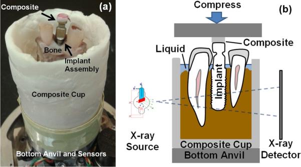
(a) Photograph of an implant-bone complex specimen prepared for biomechanical testing and (b) schematics of the in situ biomechanical testing system coupled with μ-XRM.
2.2 Implant placement and clinical measurements of implant stability
Incisors 23 and 26 were extracted. Decortication (Greenstein et al., 2009; Wallace, 2013) was performed on 23 using a #8 round bur, while the socket of incisor 26 was left intact. Implants (Straumann® Roxolid®, BL, Ø 4.1mm RC, SLActive® 14mm, TiZr, Institut Straumann AG, Basel, Switzerland) were placed using a surgical drill system (DU900, Biomet 3i, Palm Beach Gardens, FL). Straumann implants with a 4.1 mm diameter implants were selected to engage with the shorter diameter of alveolar socket (~4 mm). The torque to insert the implant was increased stepwise by the drill system until the implant platform was at the ridge crest level. The final torque value was recorded as the installation torque. An implant stability meter (100500 Osstell ISQ, Osstell AB, Gothenburg, Sweden) was used to perform the resonance frequency analysis (RFA) and measure implant stability quotient (ISQ) in the range from 1 to 100 from 4 different orientations (Sennerby and Meredith, 2008).
2.3 In situ biomechanical testing and bone-implant contact measurement
Biomechanical testing was performed on bone-implant complexes under the same conditions as stated in section 2.1. The biomechanical testing stage mentioned above was securely mounted inside a micro X-ray microscope (μ-XRM) (ZEISS Xradia 510 Versa, Carl Zeiss X-ray Microscopy, Pleasanton, CA) for in situ biomechanical testing (Fig. 1b). The specimen was compressed at 1 mm/min until a peak load of 150 N was reached. μ-XRM tomograms (resolution of ~25 μm/voxel; X-ray source energy of 100 kV) were obtained both before load was applied (no-load condition) and after load equilibrated to ~100 N (loaded condition). Obtained μ-XRM tomograms were segmented to determine contact area between bone and implant using Avizo 3D analysis software (FEI Visualization Sciences Group, Burlington, MA).
2.4 Elemental mapping in alveolar bone
The implants were removed using a dental implant torque wrench (Straumann® bone level 48 hour explantation torque device, Basel, Switzerland). The specimens were sectioned into two halves, the lingual and buccal sides using the same methods as stated in section 2.1. The topography of the specimen was imaged along with energy dispersive X-ray spectroscopy (EDS) analysis using a scanning electron microscope (SEM) (EVO, Carl Zeiss Microscopy, LLC, Thornwood, NY) (see appendix for details on specimen preparation).
2.5 Strain mapping in alveolar bone
In the tomogram, the implant was digitally removed from the alveolar socket using Avizo software (Du et al., n.d.). The deformation in bone due to load was calculated using digital volume correlation (DaVis software, LaVision Inc., Ypsilanti, MI) by correlating 3D images of the specimens at no-load and loaded conditions (Bay et al., 1999). Subsequently, the components of the 3D strain tensor were calculated from derivatives of the displacement field. The resulting 3D strain field in the alveolar bone was displayed using direct volume rendering method in the Avizo software.
3 Results
3.1 Alveolar bone geometry and bone-implant contact
A radiograph of alveolar socket 23 after tooth extraction (Fig. 2a) illustrates an opaque bright line surrounding the socket (lamina dura). Following decortication, it became thinner and more radiolucent (Fig. 2b). Although not visible from a clinical radiograph (Fig. 2c), an inadvertent drill hole was observed in the 3D rendered images at the apical portion of the osteotomy site for implant 26 (Fig. 2d and 2e).
Fig. 2.
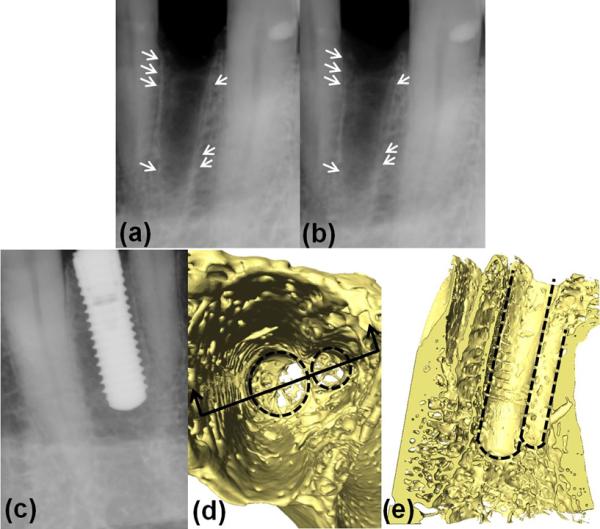
Figures (a) and (b) are radiographs of alveolar socket 23 after tooth extraction. The differences of the lamina dura (a) before and (b) after decortication are highlighted with arrows. Figure (d) and (e) are 3D rendered μ-XRM images of osteotomy for implant 26 when the implant was digitally removed. The outlines of two holes are highlighted with dashed lines. The inadvertently placed smaller drill hole is not clear in (c) the radiograph of implant 26.
A virtual section of the μ-XRM tomograms at ~4 mm below the crestal bone level is shown in Fig. 3. Thicknesses of the buccal and lingual plates were 0.34 mm and 0.85 mm for the extraction site 23 and 0.27 mm and 1.72 mm for site 26, respectively. The buccal plates were thinner than the lingual plates. Elliptical cross-sections of alveolar sockets and circular cross-sections of implants are also illustrated in Fig. 3. As a consequence of cross-section mismatch, bone-implant contact was established only at mesial and distal sides. The 3D distribution of contact area between the implants and bone is highlighted in Fig. 4. The implant-bone contact area was 24.9 mm2 and 23.5 mm2 for implant 23 and 26 (Table 1), which was about ~16% of the implant surface area. The contact area of implant 23 was distributed on both mesial and distal sides, while implant 26 was barely supported on the distal side. The contact area of implant 23 was uniform from coronal to apical regions, while implant 26 established more contact with bone in apical regions compared to coronal regions. No significant differences in the bone-implant contact areas for no-load and loaded conditions were observed.
Fig. 3.
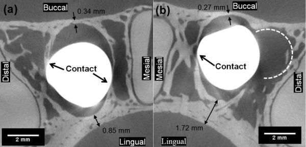
Virtual sections of μ-XRM tomograms for (a) implant 23 and (b) implant 26 placed in the osteotomies show that the implants and alveolar bone were only making contact at limited locations at the mesial and distal sides of the alveolar socket. Slice at ~4 mm below crestal bone level.
Fig. 4.
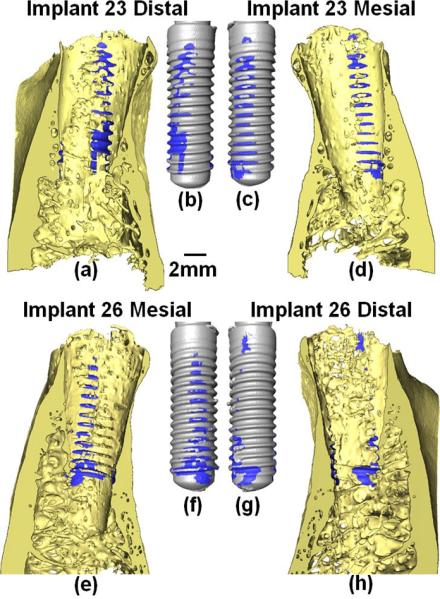
The bone-implant contact area on the (a) distal and (d) mesial sides of alveolar socket 23 and (e) mesial and (h) distal sides of alveolar socket 26. As well as the contact area on (b) distal and (c) mesial sides of implant 23 and (f) mesial and (g) distal sides of implant 26. Videos are attached in supplementary data.
Table 1.
Comparison of Implant 23 and 26
| Implant 23 | Implant 26 | |
|---|---|---|
| Installation Torque | 10 N·cm | 20 N·cm |
| ISQ | 66.5 ± 1.3 | 55.8 ± 2.2 |
| Biomechanical Testing | Incisors 23 and 26 are similar. Implants 23 and 26 are similar. Bone-implant complexes are less stiff than bone-PDL-tooth complexes. | |
| Bone-implant Contact Area | 24.9 mm2 | 23.5 mm2 |
| Bone-implant Contact Location | On both coronal and apical regions. On both mesial and distal side. | More on apical than coronal regions. Mostly on mesial side. Minimal on distal side. |
| Lamina Dura | Partly removed during decortication using round bur | Partly removed during the sequential drilling processes |
| Strain Concentration Region | Mid-buccal plate; bone-implant contact locations; crest of the lingual plate | Mid-buccal plate; bone-implant contact locations |
3.2 Elemental composition of alveolar bone
Heterogeneous elemental composition of the alveolar bone near the implant sites is shown in Fig. 5. The groove-like impressions in bone caused by implant threads can be seen under the dashed lines in Figs. 5a and 5f. Fig. 5a illustrates structural characteristics of bundle bone (lamina dura) next to the implant grooves, lamellar bone farther away from the grooves and a bright white cement line in-between. Compared with spot 2 in the lamellar bone, spot 1 in the cement line demonstrated higher levels of phosphorus (P) (Fig. 5c), calcium (Ca) (Fig. 5d), and lower levels of carbon (C) (Fig. 5b) and oxygen (O) (Fig. 5d). Fig. 5f illustrates a structure characteristic of cancellous bone in area 2 and denser bone in area 1. Lower counts in C (Fig. 5g) and higher counts in P and Ca (Fig. 5h and 5i) were observed in area 1 than in area 2 (Fig. 5j).
Fig. 5.
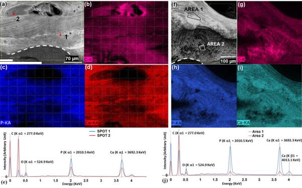
(a)(f) Topography of the alveolar bone obtained using SEM; (b)(c)(d)(g)(h)(i) Elementary mapping of the alveolar bone; (e)(j) EDS spectra of highlighted spots and areas in the alveolar bone.
3.3 Implant biomechanics and implant stability
The installation torque value was 10 N·cm for implant 23 and 20 N·cm for implant 26. However, the resonance frequency for implant 23 (ISQ of 66.5 ± 1.3) was higher than that of implant 26 (ISQ of 55.8 ± 2.2) (Table 1).
The reactionary force-displacement curves obtained from the biomechanical testing of the bone-periodontal ligament (PDL)-tooth and bone-implant complexes are illustrated in Figs. 6a, 6b and 6c. The biomechanical behaviors and stiffness values (Fig. 6d) for the two tooth complexes were similar at all displacement rates. The loading rate effect was not significantly different between the two tooth complexes. The stiffness values for the two implant-bone complexes (Fig. 6d) were also similar to each other but slightly lower than for the teeth (Fig. 6d).
Fig. 6.
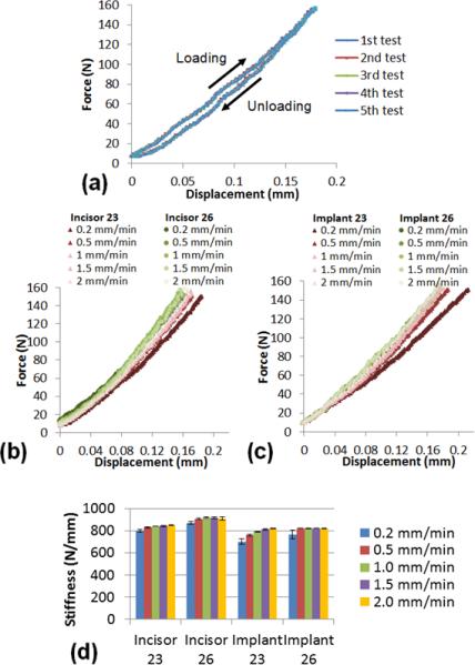
(a) Repetitive compression tests (five times) resulted in similar force-displacement curves. Reactionary force-displacement curves obtained from the biomechanical testing for (b) bone-PDL-tooth complexes and (c) bone-implant complexes. (d) Stiffness analysis for the bone-PDL-tooth complexes and bone-implant complexes.
The maximum principal strain distribution on the alveolar bone under immediate loading of implants is shown in Fig. 7. On the buccal plate adjacent to implant 26, a region of high strain concentration located ~5 to ~7 mm below the crestal bone level was observed. In contrast, no particular high strain concentration on the lingual side was observed. The high strain concentrations were also shown at bone-implant contact locations, especially on the distal side of the osteotomy site. The strain concentration on the buccal bone of implant 26 was not as high for implant 23, but the pattern of strain in the buccal plate was consistent with site 26.
Fig. 7.
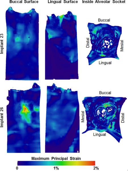
Maximum principal strain distribution on the buccal and lingual outer surfaces of the alveolar bone and inside the alveolar sockets. 3D strains in the form of videos are attached as supplementary data.
4 Discussion
Based on the results, 1) this study demonstrates a proof-of-concept by illustrating a potential tissue response to immediate implant loading through new methodology. The results add to the incomplete knowledge base in bone-implant complex and provide insights on potential function-mediated changes by illustrating a continuously adapting interface of an implant with bone. The motivation for the study was to demonstrate the manifestation of compressive loads into strains in the alveolar bone. Given that strains prompt cellular responses; our intention was to highlight the importance of mapping strains within the realm of potential bone and bone-implant interface adaptations. 2) Additionally, the measured strain is a function of the type of implant, quality of the bone in which the implant was placed, the angle of implant placement, bone-implant contact and mechanical loading. A change in any one or a combination of the conditions can cause a change in strain within alveolar bone. The latter statement reemphasizes the need for proposed methodology as it highlights gaining deeper insights on adapting bone (including a potential for maladaptation) and its integration over time with the implant, which we term as “functional integration” from a macroscale biomechanics perspective.
Functional integration is governed by several factors including initial implant stability, which in turn is affected by bone morphology (Akça et al., 2006; Alsaadi et al., 2007; Miyamoto et al., 2005) and bone quality including mineral density (Turkyilmaz et al., 2009). Fundamentally, implant stability depends on the mechanical design and surface properties of the implant, geometry and quality of bone, the contact area and friction between the implant and bone. Two identical implants were chosen in this study. Although the sample size was limited, the fact that the teeth were from the same subject minimized the potential variability from age and sex, and the natural variance within humans. Similar biomechanical behaviors of incisors 23 and 26 (Fig. 6) also implied similar bone quality and health conditions of the periodontium. Hence, various readouts obtained in this study as results of implant stability measurements can be due to bone-implant contact differences caused by different bone geometries.
Bone-implant contact is usually measured using histology (Buser et al., 1991; Jun et al., 2010; Wennerberg et al., 1995), where observations are often limited to the sectioned planes. In this noninvasive approach, the measurement of bone-implant contact through image processing of μ-XRM tomograms, minimized challenges often met in traditional histology and revealed the 3D bone-implant contact. It is important to maintain the integrity of the bone during implant placement. Implant stability depends on the area and location of bone-implant contacts. Results of this study indicated that even normal surgical procedures, such as decortication or correction of the drill path, could potentially decrease initial implant stability.
The originally uniform lamina dura of alveolar socket 23 (Fig. 2a) became radiolucent as it was thinned due to decortication (Fig. 2b). Decortication resulted in osteotomy site enlargement, with less implant stability (Table 1). Implant 23 was supported by the alveolar bone on both the mesial and distal sides, while implant 26 was mostly supported by the alveolar bone on the mesial side with minimal support on the distal side. These observed differences in contact could be the reason why implant 23 had a higher resonance frequency than implant 26. Additionally, during the placement of the implants, the apical portion of implant 26 engaged into alveolar bone, created the groove-like impressions in bone and opened the osteotomy sites. The contact established by implant 26 was mostly on the apical regions and could be the reason why installation torque for implant 26 was higher than that for implant 23.
Studies showed a strong correlation between installation torque value (ITV) and removal torque value (RTV) (Akça et al., 2007; Akkocaoglu et al., 2005), but not between periotest values (PTV) and ISQ (Jun et al., 2010). While some studies showed the correlation between ISQ and ITV/RTV are not significant (Akça et al., 2007, 2006; Akkocaoglu et al., 2005; Jun et al., 2010), to our knowledge, one study illustrated a strong correlation between ISQ and ITV (Turkyilmaz et al., 2009). In this study, the ITV for implant 23 were lower than that of implant 26. However, the ISQ for implant 23 was higher than that of implant 26.
Each implant stability measurement was evaluated by applying a single type of load in a single direction on the implant. In the installation torque measurement, a torque was applied in the direction that turns the implant into the bone. In the resonance frequency analysis, lateral forces were applied to the implants. Thus, the results of an implant stability measurement are dependent on the type and direction of the applied load. This implies that an implant showing higher stability in one measurement might show lower stability when tested for stability in a different direction. Hence, multiple and complementary methods used in this study were to gain a comprehensive understanding of the implant stability.
A vertical compressive force was applied on the implants during the in situ biomechanical testing to mimic the dominant functional load. The resulting stiffness of a bone-PDL-tooth or bone-implant complex is a combined stiffness of the tooth or implant and the supporting structures. For implants, the supporting structure is alveolar bone. For teeth, the supporting structures are the PDL and bone. In this study, it is likely that the dampening effect of PDL was affected by the γ-radiation. Also, support from interstitial fluid was minimally detected in this study. Therefore, the measured stiffness was predominantly limited to hard tissues.
Repetitive biomechanical testing for the same specimen resulted in similar force-displacement curves (Fig. 6a). It indicated that the error due to our experimental approach is negligible within the detectable ranges of our instrumentation. The biomechanical behaviors for the two bone-PDL-teeth complexes were similar (Fig. 6b). This implied similar load bearing aspects of respective complexes for incisors 23 and 26, thus illustrating a foundation with similar physical properties on which implants were later introduced. Ti/Zr implants have higher elastic modulus (80-130 GPa (Soboyejo, 2003)) than teeth (14-17 GPa for cementum, 22-27 GPa for tubular dentin (Ho et al., 2007) and 75-100 GPa for enamel (Park et al., 2008)), and possibly higher stiffness than the teeth. However, the biomechanical testing in this study illustrated that the stiffness values for the implant complexes were slightly lower than the stiffness values for respective tooth complexes (Fig. 6d). Biomechanical comparisons indicated that the supporting alveolar bone for implants was not stiffer than the supporting structures for teeth before implant placement, perhaps due to the decreased implant contact area (Fig. 4e and 4f).
Bone-implant contact under load prompts mechanical strains predominantly at the bone-implant interface and within alveolar bone. Very little is known about mechanical strains introduced from immediate implant loading. A novel aspect of our study was to evaluate strains within bone due to immediate implant loading using DVC, a non-invasive technique without assumptions of the mechanical properties of supporting tissues. As shown in Fig. 5, alveolar bone is heterogeneous in structure and elemental composition. Hence, the assumptions of mechanical properties of bone in other modeling methods, such as finite element method, might over-simplify reality and produce inaccurate results.
Based on the loading and experimental conditions, strain concentrations in the mid-buccal bone were observed (Fig. 7) due to mesio-distal expansion of the alveolar bone resulting from implant loading and more importantly from the contact geometry and dimensions of the buccal plates. Tensile strains were induced, in the thinner portion of the buccal plates. As measured in Fig. 3, the lingual plate is 2.5 to 6.5 times thicker than the buccal plate for implants 23 and 26, respectively. It can also be seen on the cross-section planes in Fig. 4. Therefore, the strain concentration on buccal plate was higher for implant 26 than that for implant 23. Concurring with the argument, strain concentration was also observed in thin crestal part of the lingual plate for implant 23 (Fig. 4).
Strain mapping on the alveolar socket surface is also shown in Fig. 7. Unlike natural teeth, which transmit mechanical load to alveolar bone through the PDL surrounding the tooth, in the bone-implant complex, the mechanical load is transmitted directly from the implant to alveolar bone through limited contact areas (Fig. 4). In addition, the applied load during the biomechanical testing was not necessarily along the long axis of the implants, due to the geometry of the alveolar socket. This could have induced a lateral component of the applied load causing strain concentrations on unintended sides of the alveolar socket (Fig. 7). From a clinical perspective, while the strain concentrations in buccal plate could explain mid-buccal plate bone loss (Chen and Buser, 2014, 2009; Kan et al., 2010). It should be noted that the results presented in this study are limited to the type of implant used in this study, placement of implant, quality of bone, angle of loading and bone-implant contact conditions.
A future extension of this work could be to develop a finite element model to investigate the effects of bone augmentation through increased thickness in regions of interest following which strain and stress concentrations could be evaluated. Results of this study have established a proof-of-concept that bone-implant contact can affect biomechanics and mechanical strain within bone that is not in contact with the implant. Through these results, it is conceivable that bone-implant contact mechanics will further clarify the mechanobiology of events that can determine the long-term effectiveness of implants by mapping adaptations of bone-implant interface and bone per se.
5 Conclusions
This study was performed by systematically mimicking clinical procedures during patient treatment. The results of this study are only relevant to immediately placed and loaded implants, and lack the influence of multiple factors such as blood, grafting, suturing or wound healing. Although the sample size in this study was small, it serves as a proof-of-concept. Results show that the bone-implant contact was limited to ~16% of the implant surface area and the established contact was primarily on the mesial and distal regions of the extraction sites. From a biomechanics perspective, the observed strain concentrations are where they would be expected as the engaged bone at the implant threads, but also in sites of bone not in contact with the implant.
The results of this study are only relevant to immediately placed and loaded implants, with no source for blood and subsequent osseointegration. Additionally, the vertical load applied during biomechanical testing only represents one component within the more realistic multi-components functional loads. Additional systematic studies, using more specimens and/or an animal model, are needed to account for complicated physiological conditions. Additionally, the measured implant biomechanics can be affected by the presence and/or absence of adjacent teeth. In order to gain additional insights of strain induced bone-implant functional adaptations, future investigations are needed to compare the biomechanics of dental implants with or without the support of adjacent teeth. The methodology provided in this study can be used to investigate the clinical complications and can provide insights from which future improvements in surgical planning and techniques can be formulated.
Supplementary Material
Acknowledgement
This research is supported by NIH (Grant R01DE022032 and S10RR026645). The authors are grateful to Mr. Edward Garcia at UCSF School of Dentistry, Joel Mancuso and Chris Rieken at Carl Zeiss Microscopy and Brian Miller at Bruker AXS Inc. for their technical assistance. The authors would also like to thank Straumann AG for providing the dental implants in this study.
Footnotes
Publisher's Disclaimer: This is a PDF file of an unedited manuscript that has been accepted for publication. As a service to our customers we are providing this early version of the manuscript. The manuscript will undergo copyediting, typesetting, and review of the resulting proof before it is published in its final citable form. Please note that during the production process errors may be discovered which could affect the content, and all legal disclaimers that apply to the journal pertain.
Conflict of interest statement
We acknowledge that all authors do not have any conflict of interest, and were fully involved in the study and preparation of the manuscript.
References
- Akça K, Akkocaoglu M, Cömert A, Tekdemir I, Cehreli MC. Bone strains around immediately loaded implants supporting mandibular overdentures in human cadavers. Int. J. Oral Maxillofac. Implants. 2007;22:101–9. [PubMed] [Google Scholar]
- Akça K, Chang T, Tekdemir I, Fanuscu MI. Biomechanical aspects of initial intraosseous stability and implant design: a quantitative micro-morphometric analysis. Clin. Oral Implants Res. 2006;17:465–72. doi: 10.1111/j.1600-0501.2006.01265.x. [DOI] [PubMed] [Google Scholar]
- Akkocaoglu M, Uysal S, Tekdemir I, Akca K, Cehreli MC. Implant design and intraosseous stability of immediately placed implants: a human cadaver study. Clin. Oral Implants Res. 2005;16:202–9. doi: 10.1111/j.1600-0501.2004.01099.x. [DOI] [PubMed] [Google Scholar]
- Alsaadi G, Quirynen M, Michiels K, Jacobs R, van Steenberghe D. A biomechanical assessment of the relation between the oral implant stability at insertion and subjective bone quality assessment. J. Clin. Periodontol. 2007;34:359–66. doi: 10.1111/j.1600-051X.2007.01047.x. [DOI] [PubMed] [Google Scholar]
- Asundi A, Kishen A. A strain gauge and photoelastic analysis of in vivo strain and in vitro stress distribution in human dental supporting structures. Arch. Oral Biol. 2000a;45:543–50. doi: 10.1016/s0003-9969(00)00031-5. [DOI] [PubMed] [Google Scholar]
- Asundi A, Kishen A. Stress distribution in the dento-alveolar system using digital photoelasticity. Proc. Inst. Mech. Eng. H. 2000b;214:659–667. doi: 10.1243/0954411001535688. [DOI] [PubMed] [Google Scholar]
- Asundi A, Kishen A. Advanced digital photoelastic investigations on the tooth-bone interface. J. Biomed. Opt. 2001;6:224–230. doi: 10.1117/1.1344587. [DOI] [PubMed] [Google Scholar]
- Baggi L, Cappelloni I, Di Girolamo M, Maceri F, Vairo G. The influence of implant diameter and length on stress distribution of osseointegrated implants related to crestal bone geometry: a three-dimensional finite element analysis. J. Prosthet. Dent. 2008;100:422–31. doi: 10.1016/S0022-3913(08)60259-0. [DOI] [PubMed] [Google Scholar]
- Bay BK, Smith TS, Fyhrie DP, Saad M. Digital volume correlation: Three-dimensional strain mapping using X-ray tomography. Exp. Mech. 1999;39:217–226. [Google Scholar]
- Bozkaya D, Muftu S, Muftu A. Evaluation of load transfer characteristics of five different implants in compact bone at different load levels by finite elements analysis. J. Prosthet. Dent. 2004;92:523–30. doi: 10.1016/j.prosdent.2004.07.024. [DOI] [PubMed] [Google Scholar]
- Brunski JB. In vivo bone response to biomechanical loading at the bone/dental-implant interface. Adv. Dent. Res. 1999;13:99–119. doi: 10.1177/08959374990130012301. [DOI] [PubMed] [Google Scholar]
- Buser D, Schenk RK, Steinemann S, Fiorellini JP, Fox CH, Stich H. Influence of surface characteristics on bone integration of titanium implants. A histomorphometric study in miniature pigs. J. Biomed. Mater. Res. 1991;25:889–902. doi: 10.1002/jbm.820250708. [DOI] [PubMed] [Google Scholar]
- Chen ST, Buser D. Clinical and esthetic outcomes of implants placed in postextraction sites. Int. J. Oral Maxillofac. Implants. 2009;24(Suppl):186–217. [PubMed] [Google Scholar]
- Chen ST, Buser D. Esthetic outcomes following immediate and early implant placement in the anterior maxilla--a systematic review. Int. J. Oral Maxillofac. Implants. 2014;29(Suppl):186–215. doi: 10.11607/jomi.2014suppl.g3.3. [DOI] [PubMed] [Google Scholar]
- Choi H-H, Chung C-H, Kim S-G, Son M-K. Reliability of 2 implant stability measuring methods in assessment of various periimplant bone loss: an in vitro study with the Periotest and Osstell Mentor. Implant Dent. 2014;23:51–6. doi: 10.1097/ID.0000000000000000. [DOI] [PubMed] [Google Scholar]
- Du J, Jang A, Curtis D, Gu A, Prevost R, Merkle A, Ho S. Imaging artifacts and strain mapping in a bone-implant complex. n.d under review.
- Eugene Roberts W, Huja SH, Roberts JA. Bone modeling: biomechanics, molecular mechanisms, and clinical perspectives. Semin. Orthod. 2004;10:123–161. [Google Scholar]
- Greenstein G, Cavallaro J, Tarnow D. Assessing bone's adaptive capacity around dental implants: a literature review. J. Am. Dent. Assoc. 2013;144:362–8. doi: 10.14219/jada.archive.2013.0129. [DOI] [PubMed] [Google Scholar]
- Greenstein G, Greenstein B, Cavallaro J, Tarnow D. The role of bone decortication in enhancing the results of guided bone regeneration: a literature review. J. Periodontol. 2009;80:175–89. doi: 10.1902/jop.2009.080309. [DOI] [PubMed] [Google Scholar]
- Hamer AJ, Strachan JR, Black MM, Ibbotson CJ, Stockley I, Elson RA. Biochemical properties of cortical allograft bone using a new method of bone strength measurement. A comparison of fresh, fresh-frozen and irradiated bone. J. Bone Joint Surg. Br. 1996;78:363–368. [PubMed] [Google Scholar]
- Ho SP, Marshall SJ, Ryder MI, Marshall GW. The tooth attachment mechanism defined by structure, chemical composition and mechanical properties of collagen fibers in the periodontium. Biomaterials. 2007;28:5238–45. doi: 10.1016/j.biomaterials.2007.08.031. [DOI] [PMC free article] [PubMed] [Google Scholar]
- Jantarat J, Panitvisai P, Palamara JE, Messer HH. Comparison of methods for measuring cuspal deformation in teeth. J. Dent. 2001;29:75–82. doi: 10.1016/s0300-5712(00)00040-3. [DOI] [PubMed] [Google Scholar]
- Jiroušek O, Jandejsek I, Vavřík D. Evaluation of strain field in microstructures using micro-CT and digital volume correlation. J. Instrum. 2011;6:C01039–C01039. [Google Scholar]
- Jun S, Chang BMW, Weber H, Kwon J-J. Comparison of initial stability parameters and histomorphometric analysis of implants inserted into extraction sockets: human fresh cadaver study. Int. J. Oral Maxillofac. Implants. 2010;25:985–90. [PubMed] [Google Scholar]
- Kan JYK, Rungcharassaeng K, Lozada JL, Zimmerman G. Facial gingival tissue stability following immediate placement and provisionalization of maxillary anterior single implants: a 2- to 8-year follow-up. Int. J. Oral Maxillofac. Implants. 2010;26:179–87. [PubMed] [Google Scholar]
- Kishen A, Tan KBC, Asundi A. Digital moiré interferometric investigations on the deformation gradients of enamel and dentine: an insight into non-carious cervical lesions. J. Dent. 2006;34:12–8. doi: 10.1016/j.jdent.2005.02.008. [DOI] [PubMed] [Google Scholar]
- Miyamoto I, Tsuboi Y, Wada E, Suwa H, Iizuka T. Influence of cortical bone thickness and implant length on implant stability at the time of surgery--clinical, prospective, biomechanical, and imaging study. Bone. 2005;37:776–80. doi: 10.1016/j.bone.2005.06.019. [DOI] [PubMed] [Google Scholar]
- Monje A, Ortega-Oller I, Galindo-Moreno P, Catena A, Monje F, O'Valle F, Suarez F, Wang H-L. Sensitivity of resonance frequency analysis for detecting early implant failure: a case-control study. Int. J. Oral Maxillofac. Implants. 2014;29:456–61. doi: 10.11607/jomi.3357. [DOI] [PubMed] [Google Scholar]
- O'Sullivan D, Sennerby L, Meredith N. Measurements comparing the initial stability of five designs of dental implants: a human cadaver study. Clin. Implant Dent. Relat. Res. 2000;2:85–92. doi: 10.1111/j.1708-8208.2000.tb00110.x. [DOI] [PubMed] [Google Scholar]
- Olivé J, Aparicio C. Periotest method as a measure of osseointegrated oral implant stability. Int. J. Oral Maxillofac. Implants. 1990;5:390–400. [PubMed] [Google Scholar]
- Ostman P-O, Hellman M, Wendelhag I, Sennerby L. Resonance frequency analysis measurements of implants at placement surgery. Int. J. Prosthodont. 2006;19:77–83. discussion 84. [PubMed] [Google Scholar]
- Panjabi MM, Krag M, Summers D, Videman T. Biomechanical time-tolerance of fresh cadaveric human spine specimens. J. Orthop. Res. 1985;3:292–300. doi: 10.1002/jor.1100030305. [DOI] [PubMed] [Google Scholar]
- Park S, Quinn JB, Romberg E, Arola D. On the brittleness of enamel and selected dental materials. Dent. Mater. 2008;24:1477–85. doi: 10.1016/j.dental.2008.03.007. [DOI] [PMC free article] [PubMed] [Google Scholar]
- Popowics TE, Rensberger JM, Herring SW. Enamel microstructure and microstrain in the fracture of human and pig molar cusps. Arch. Oral Biol. 2004;49:595–605. doi: 10.1016/j.archoralbio.2004.01.016. [DOI] [PubMed] [Google Scholar]
- Qian L, Todo M, Morita Y, Matsushita Y, Koyano K. Deformation analysis of the periodontium considering the viscoelasticity of the periodontal ligament. Dent. Mater. 2009;25:1285–92. doi: 10.1016/j.dental.2009.03.014. [DOI] [PubMed] [Google Scholar]
- Sennerby L, Meredith N. Implant stability measurements using resonance frequency analysis: biological and biomechanical aspects and clinical implications. Periodontol. 2008;2000;47:51–66. doi: 10.1111/j.1600-0757.2008.00267.x. [DOI] [PubMed] [Google Scholar]
- Soboyejo W. Mechanical properties of engineered materials, New York. CRC; New York: 2003. [Google Scholar]
- Ten Cate AR. Oral histology: development, structure, and function. 5th ed. Mosby; St. Louis, MO: 1998. [Google Scholar]
- Tiossi R, Lin L, Rodrigues RCS, Heo YC, Conrad HJ, Mattos GC, De, Ribeiro RF, Fok ASL. Digital image correlation analysis of the load transfer by implant-supported restorations. J. Biomech. 2011;44:1008–1013. doi: 10.1016/j.jbiomech.2011.02.015. [DOI] [PubMed] [Google Scholar]
- Turkyilmaz I, Sennerby L, McGlumphy EA, Tözüm TF. Biomechanical aspects of primary implant stability: a human cadaver study. Clin. Implant Dent. Relat. Res. 2009;11:113–9. doi: 10.1111/j.1708-8208.2008.00097.x. [DOI] [PubMed] [Google Scholar]
- Van Oosterwyck H, Duyck J, Vander Sloten J, Van der Perre G, De Cooman M, Lievens S, Puers R, Naert I. The influence of bone mechanical properties and implant fixation upon bone loading around oral implants. Clin. Oral Implants Res. 1998;9:407–18. doi: 10.1034/j.1600-0501.1996.090606.x. [DOI] [PubMed] [Google Scholar]
- Verhulp E, van Rietbergen B, Huiskes R. A three-dimensional digital image correlation technique for strain measurements in microstructures. J. Biomech. 2004;37:1313–20. doi: 10.1016/j.jbiomech.2003.12.036. [DOI] [PubMed] [Google Scholar]
- Wallace SC. Guided bone regeneration for socket preservation in molar extraction sites: histomorphometric and 3D computerized tomography analysis. J. Oral Implantol. 2013;39:503–9. doi: 10.1563/AAID-JOI-D-13-00001. [DOI] [PubMed] [Google Scholar]
- Wang RZ, Weiner S. Strain-structure relations in human teeth using Moiré fringes. J. Biomech. 1998;31:135–41. doi: 10.1016/s0021-9290(97)00131-0. [DOI] [PubMed] [Google Scholar]
- Wazen RM, Currey JA, Guo H, Brunski JB, Helms JA, Nanci A. Micromotion-induced strain fields influence early stages of repair at bone-implant interfaces. Acta Biomater. 2013;9:6663–74. doi: 10.1016/j.actbio.2013.01.014. [DOI] [PMC free article] [PubMed] [Google Scholar]
- Weinmann JP. Bone changes related to eruption of the teeth. Angle Orthod. 1941;11:83–99. [Google Scholar]
- Weinmann JP, Sicher H. Bone and Bones: fundamentals of bone biology. 2nd ed. Mosby; St. Louis, MO: 1955. [Google Scholar]
- Wennerberg A, Albrektsson T, Andersson B, Krol JJ. A histomorphometric and removal torque study of screw-shaped titanium implants with three different surface topographies. Clin. Oral Implants Res. 1995;6:24–30. doi: 10.1034/j.1600-0501.1995.060103.x. [DOI] [PubMed] [Google Scholar]
- Wood JD, Wang R, Weiner S, Pashley DH. Mapping of tooth deformation caused by moisture change using moiré interferometry. Dent. Mater. 2003;19:159–166. doi: 10.1016/s0109-5641(02)00025-8. [DOI] [PubMed] [Google Scholar]
- Zaslansky P, Currey JD, Friesem AA, Weiner S. Phase shifting speckle interferometry for determination of strain and Young's modulus of mineralized biological materials: a study of tooth dentin compression in water. J. Biomed. Opt. 2005;10:024020. doi: 10.1117/1.1891505. [DOI] [PubMed] [Google Scholar]
- Zaslansky P, Friesem AA, Weiner S. Structure and mechanical properties of the soft zone separating bulk dentin and enamel in crowns of human teeth: insight into tooth function. J. Struct. Biol. 2006;153:188–99. doi: 10.1016/j.jsb.2005.10.010. [DOI] [PubMed] [Google Scholar]
- Zauel R, Yeni YN, Bay BK, Dong XN, Fyhrie DP. Comparison of the linear finite element prediction of deformation and strain of human cancellous bone to 3D digital volume correlation measurements. J. Biomech. Eng. 2006;128:1–6. doi: 10.1115/1.2146001. [DOI] [PubMed] [Google Scholar]
- Zhang D, Mao S, Lu C, Romberg E, Arola D. Dehydration and the dynamic dimensional changes within dentin and enamel. Dent. Mater. 2009;25:937–45. doi: 10.1016/j.dental.2009.01.101. [DOI] [PMC free article] [PubMed] [Google Scholar]
Associated Data
This section collects any data citations, data availability statements, or supplementary materials included in this article.


