Significance
We have built a new type of mechanical metamaterial: a “gyroscopic metamaterial” composed of rapidly spinning objects that are coupled to each other. At the edges of these materials, we find sound waves that are topologically protected (i.e. they cannot be scattered backward or into the bulk). These waves, which propagate in one direction only, are directly analogous to edge currents in quantum Hall systems. Through a mathematical model, we interpret the robustness of these edge waves in light of the subtle topological character of the bulk material. Crucially, these edge motions can be controlled by distorting the metamaterial lattice, opening new avenues for the control of sound in matter.
Keywords: topological mechanics, gyroscopic metamaterial, metamaterial
Abstract
Topological mechanical metamaterials are artificial structures whose unusual properties are protected very much like their electronic and optical counterparts. Here, we present an experimental and theoretical study of an active metamaterial—composed of coupled gyroscopes on a lattice—that breaks time-reversal symmetry. The vibrational spectrum displays a sonic gap populated by topologically protected edge modes that propagate in only one direction and are unaffected by disorder. We present a mathematical model that explains how the edge mode chirality can be switched via controlled distortions of the underlying lattice. This effect allows the direction of the edge current to be determined on demand. We demonstrate this functionality in experiment and envision applications of these edge modes to the design of one-way acoustic waveguides.
A vast range of mechanical structures, including bridges, covalent glasses, and conventional metamaterials, can be ultimately modeled as networks of masses connected by springs (1–6). Recent studies have revealed that despite its apparent simplicity, this minimal setup is sufficient to construct topologically protected mechanical states (7–11) that mimic the properties of their quantum analogs (12). This follows from the fact that, irrespective of its classic or quantum nature, a periodic material with a gapped spectrum of excitations can display topological behavior as a result of the nontrivial topology of its band structure (13–21).
All such mechanical systems, however, are invariant under time reversal because their dynamics are governed by Newton’s second law, which, unlike the Schrödinger equation, is second order in time. If time-reversal symmetry is broken, as in recently suggested acoustic structures containing circulating fluids (16), theoretical work (13) has suggested that phononic chiral topological edge states that act as unidirectional waveguides resistant to scattering off impurities could be supported. In this paper, we show that by creating a coupled system of gyroscopes, a “gyroscopic metamaterial,” we can produce an effective material with intrinsic time-reversal symmetry breaking. As a result, our gyroscopic metamaterials support topological mechanical modes analogous to quantum Hall systems, which have robust chiral edge states (22–24). We demonstrate these effects by building a real system of gyroscopes coupled in a honeycomb lattice. Our experiments show long-lived, unidirectional transport along the edge, even in the presence of significant defects. Moreover, our theoretical analysis indicates that direction of edge propagation is controlled both by the gyroscope spin and the geometry of the underlying lattice. As a result, deforming the lattice of gyroscopes allows one to control the edge mode direction, offering unique opportunities for engineering novel materials.
Much of the counterintuitive behavior of rapidly spinning objects originates from their large angular momentum, which endows the axis of spin with a resistance to change. If we fix one end of a gyroscope and apply a force, , to the opposing free end of the spinning axis, we produce a torque of , where is the axis of the gyroscope, pointing from the fixed to the free end. In the fast spinning limit, the response of the gyroscope’s axis is
| [1] |
where ω is the gyroscope angular frequency and I is its rotational inertia. The behavior of a gyroscope differs from that of a simple mass in two important ways: (i) It moves perpendicular to applied forces and (ii) its response is first order in time. The canonical example of this unusual behavior is precession: A spinning top does not simply fall over, but rather its free end orbits around the contact point (precesses) with a constant period, , where is the distance from the pivot point to center of gravity.
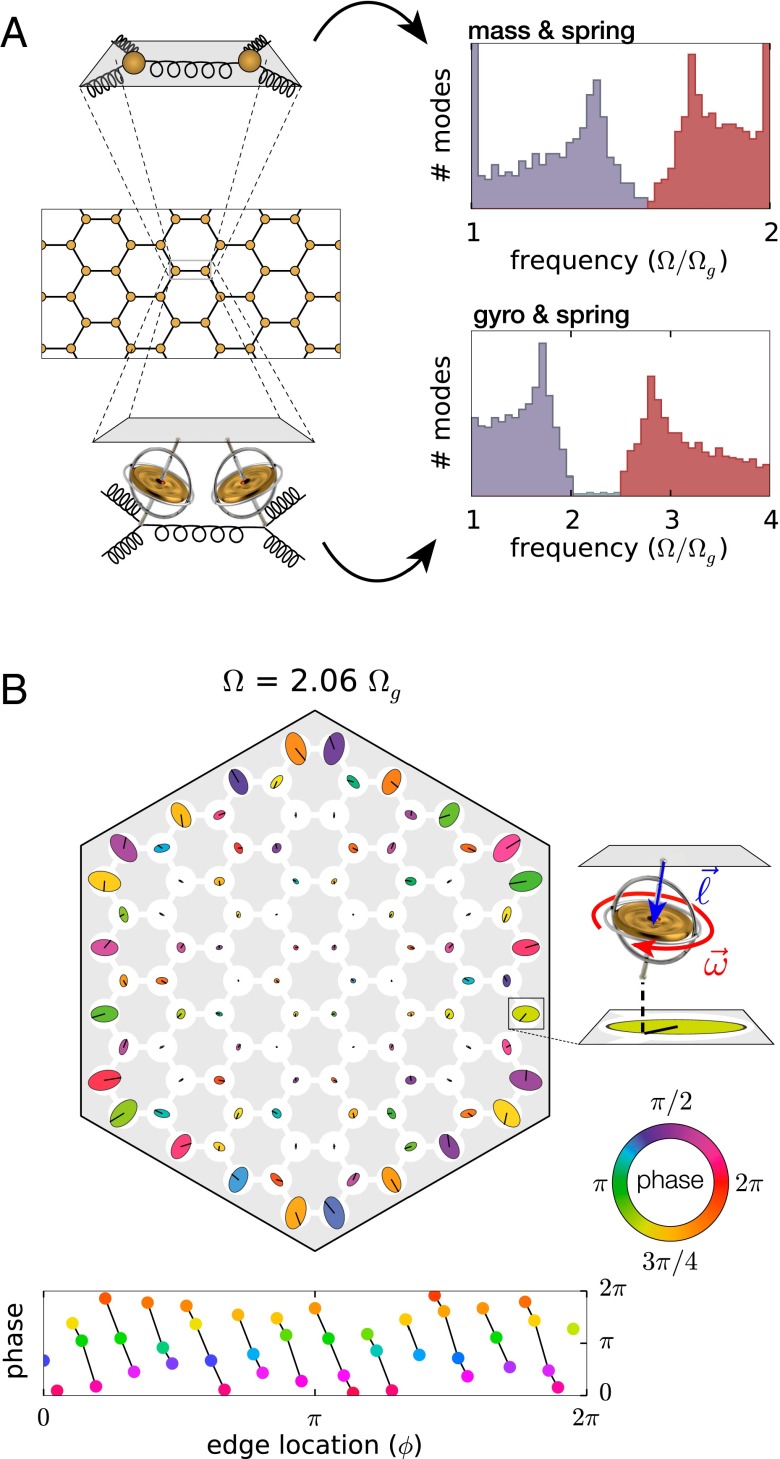
What happens if we replace the masses in a conventional mechanical metamaterial with gyroscopes? A first glimpse is provided by a normal mode analysis of honeycomb lattices composed of mass–spring and gyroscope–spring networks. The density of states of these two systems (Fig. 1A) shows qualitatively similar features: Each is characterized by two bands, a lower “acoustic” band (where neighboring sites move in phase) and an upper “optical” band (where neighboring sites move out of phase). The connections between these two bands, however, show key differences: In the mass–spring system the two bands touch at a Dirac point, whereas in the gyroscopic system a gap opens up between the bands. Crucially, this gap is not empty, but populated by nearly equally spaced modes and the number of these edge modes scales with the length of the edge. Examination of these gap modes reveals them to be confined to the edge and to be chiral: The phases always rotate in the same direction as one moves around the lattice (Fig. 1B). As we show below, these edge modes are topologically robust and can therefore serve as unidirectional waveguides.
Fig. 1.
Gyroscopic metamaterials and edge states. (A) A comparison between the density of states of a mass–spring (Top) and gyroscopic metamaterial (Bottom) on a honeycomb lattice. In both networks neighboring masses (gyroscopes) are coupled by springs and each mass(gyroscope) feels a restoring force toward its equilibrium position. In the gyroscope network, the spring interaction frequency is =. The acoustic and optical bands of the network of masses connected by springs meet at a (Dirac) point. By contrast, in the network of gyroscopes connected by springs, there is a gap between acoustic and optical bands that is populated by chiral edge modes. (B) A normal mode (evaluated numerically) between the acoustic and optical bands in a lattice of 96 gyroscopes. The shape of each orbit in the normal mode is indicated with ellipses and the phase at a fixed time is indicated via color. The phase of the gyroscopes along the edge is indicated below, showing the phase velocity is unidirectional. This combined with the absence of a corresponding mode with opposite phase velocity is the key characteristic of chiral edge states.
It is far from obvious that in a real system the phonon spectrum would be resistant to the presence of both disorder (lattice imperfections, gyroscopic nonuniformity, etc.) and mixed-order dynamics (e.g., nutation). However, an appealing feature of topological states is that they are often resistant to disorder, suggesting that they may be useful for acoustic applications and observable under a wide range of experimental conditions.
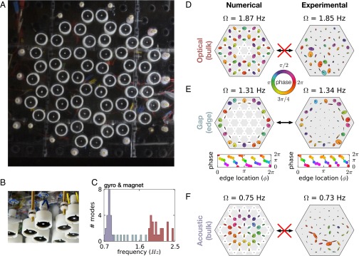
To explore the relevance of these effects, we have assembled a prototype system of 54 interacting gyroscopes on a honeycomb lattice (Fig. 2A and Fig. S2). Our gyroscopes consist of small dc motors spinning cylindrical masses at ∼300 Hz (with variation in motor speed); each is suspended from a top plate by a weak spring (Fig. 2B), producing an individual precession frequency of Hz. To couple these gyroscopes in a lattice, a small neodymium magnet is placed in each spinning mass with its moment aligned vertically, causing the gyroscopes to repel. For small displacements, this creates a linear effective spring-like force between gyroscopes that is comparable in strength to the gravitational pinning force.
Fig. 2.
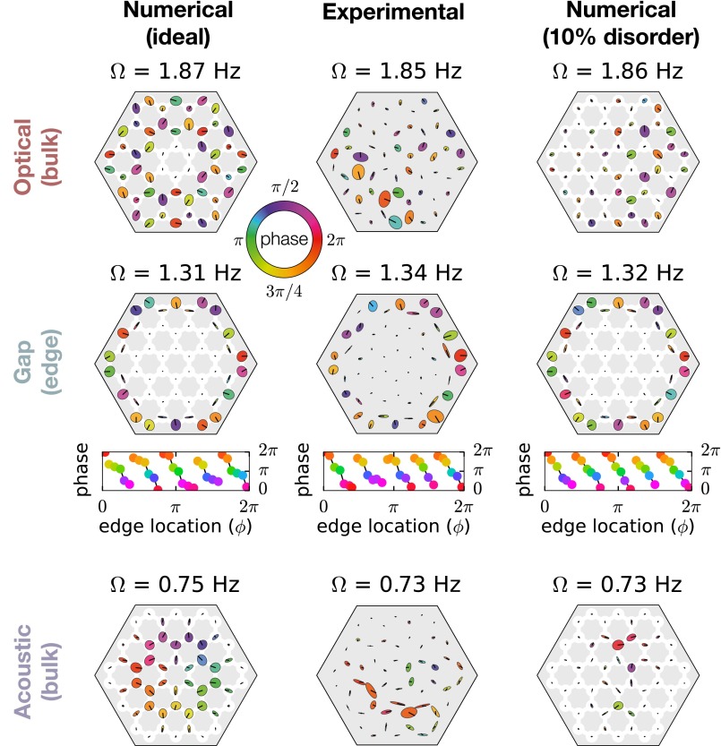
Demonstration of robustness of edge modes in experiment. (A) A picture of the experimental system as viewed from below. (B) The edge of the experimental lattice from the side, showing the construction of the individual gyroscopes as well as the fixed magnets around the edge that provide the lateral confinement. (C) The calculated histogram of normal mode frequencies for an array of 54 gyroscopes arranged in a honeycomb lattice (no disorder) is shown. The frequencies range from 0.7 to 2.5 Hz. (D–F) A comparison of calculated normal modes in an ideal magnetic-gyroscope network (Left) as measured in an experimental system (Right). For each system a mode is shown in (D) the optical band, (E) the band gap, and (F) the acoustic band. Disorder has a strong effect on bulk mode profiles. However, the gap mode profiles correspond much more closely to the ideal modes in shape, orientation, and phase of the gyroscope orbits.
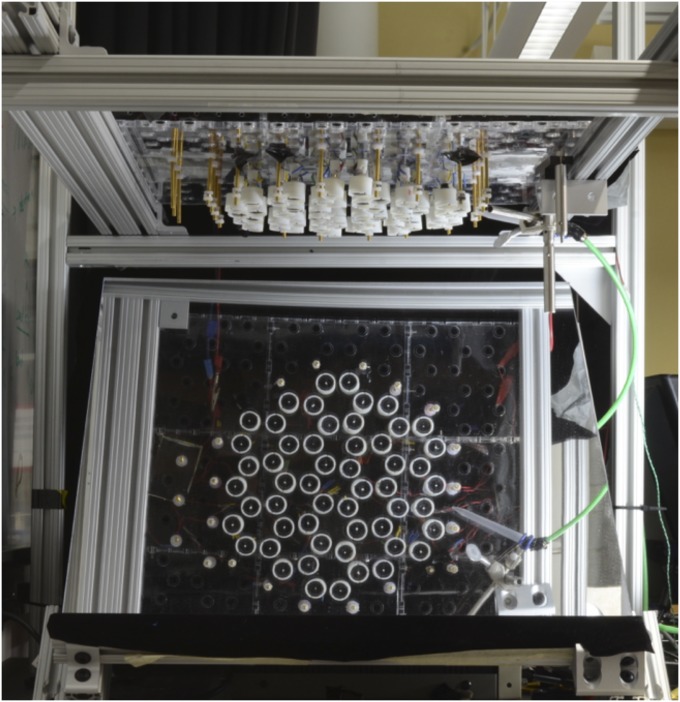
Fig. S2.
The gyroscopic metamaterial is composed of 54 gyroscopes suspended by springs and coupled by magnetic dipole interactions.
The magnetically coupled system is conceptually equivalent to the system of gyrosocopes connected by springs discussed earlier; the linearized magnetic coupling differs, however, in detail from the coupling given by springs because the equilibrium results from the cancellation of opposing forces instead of the absence of forces. As detailed in Supporting Information, this results in a mode spectrum that is shifted to lower frequencies (Fig. 2C), compared with a spring-coupled gyroscope system (Fig. 1A). However, the topological character of the band structure is not affected and acoustic and optical bands are still apparent with chiral edge modes in between.
To test the mechanical response of the gyroscopic metamaterial, we excite it with periodic bursts of air through a small nozzle and follow the resulting disturbance. We probe the normal modes by weakly exciting a single gyroscope at a fixed frequency for many (>100) periods and recording the resulting motion of the network. All excitations were kept to small amplitudes (<10% of the lattice spacing) to avoid the nonlinearities associated with coupling the gyroscopes magnetically (Figs. S3–S5).
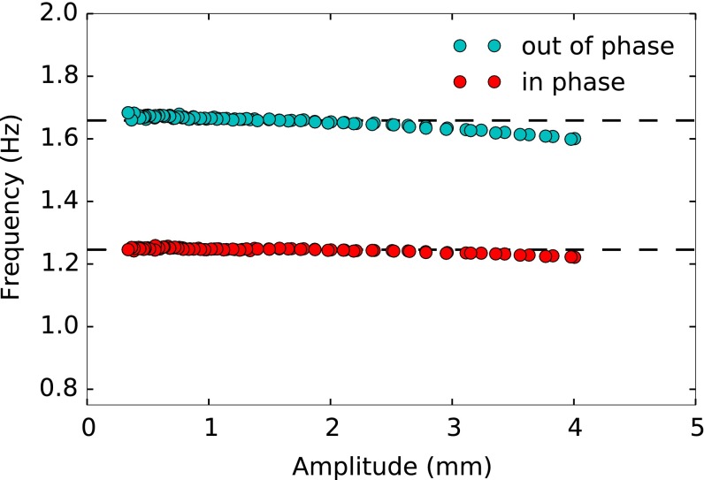
Fig. S3.
The effect of oscillation amplitude on the two normal mode frequencies in a system of two gyroscopes. The frequencies are shifted by ∼5% as the oscillation amplitude increases to above 10% of the gyroscope separation.
Fig. S5.
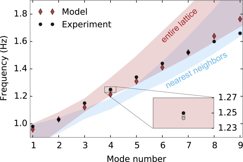
A comparison between the experiment and magnetic model for gap mode frequencies. The red (blue) shaded region indicates the possible values of gap mode frequencies for mode numbers 1–9 from calculations using measured m and values with entire lattice (nearest-neighbor) coupling. Mode numbers 1–9 are observed in the experiment with a gap extending from Hz. Modes 8 and 9 show some mixing with bulk modes. The diamonds show values for a theoretical model with Am2 and mm, corresponding to Hz (with entire lattice coupling). For this system, Hz, which was determined by measuring a single gyroscope. (Inset ) The change in frequency observed when the mode amplitude is increased from mm (measured as the largest displacement of a single gyroscope).
The effect of disorder inherent to our experiment (e.g., variation in motor speed and gyroscope pivot position) can be clearly seen in the comparison between the structure of bulk modes as shown in Fig. 2 D and F for the idealized (Left) and experimental system (Right). There is little overall agreement between calculated and measured modes, though acoustic modes show approximate in-phase oscillation of adjacent gyroscopes and optical modes show approximate out-of-phase oscillation of adjacent gyroscopes. This is characteristic of the effects of disorder (25), which produces the same effect in numerically evaluated modes with comparable disorder (Fig. S6).
Fig. S6.
Comparison between ideal numerical modes, experimental modes, and numerically calculated modes with 10% disorder. The effect of random disorder on mode profiles is qualitatively similar to the mode profiles observed in the experimental system, which had a similar amount of disorder.
Despite these experimental imperfections, exciting a mode in the gap between the acoustic and optical bands produces clean excitations along the edge (Fig. 2E). The orientations and relative orbit sizes of these modes closely match the modes numerically computed for an idealized model. A comparison between calculated and measured edge mode frequencies is shown in Fig. S5. The robustness of these modes against disorder is characteristic of their topological character.
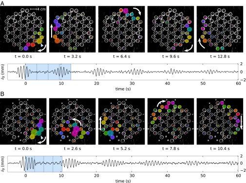
To demonstrate that our experimental metamaterial functions as a unidirectional waveguide, we excite a single edge gyroscope for five periods at a frequency in the gap. As shown in Fig. 3A and Movie S1, the resulting excitation propagates in only one direction around the edge of the lattice. The motion of this wave packet around the edge is persistent, circumnavigating the boundary several times. As expected, short excitations at a frequency not in the band gap do not produce a similar robust edge excitation (Movie S2). Crucially, this indicates that the chiral edge modes are topologically protected from coupling to the bulk modes, functioning as an efficient one-directional waveguide.
Fig. 3.
Unidirectional waveguide modes in experiment. (A) A single edge gyroscope is excited for five periods; subsequent images show the excitation propagation clockwise around the edge. The bottom graph indicates the displacement of one gyroscope (indicated with a triangle) in the y direction; the excitation is seen to persist for many cycles around the edge. (B) The same experiment as in A, but with three gyroscopes removed from the bottom edge and replaced with fixed magnets (to keep the system in equilibrium). Owing to the topological nature of the edge modes, the excitation propagates around the disturbance.
We further demonstrate the robustness of these edge modes by intentionally introducing disorder in the lattice, for example by removing three gyroscopes. As shown in Movie S3 and Fig. 3B, even this significant disturbance does not destroy the chiral edge modes. An excitation on the edge is seen to move around this disturbance—in the same direction as before—and emerge undisturbed on the other side. Remarkably, the excitation traverses the defect region without scattering backward or into the bulk. As before, the resilience of the edge modes suggests these edge states are topological in character.
To analyze the origin of these effects, we return to an ideal coupled gyroscope model. For simplicity, we represent the displacement of the tip of the gyroscope from equilibrium as . In this form, the linearized version of Eq. 1 is , where is the complex representation of the interaction force and the complex phase, i, arises from the cross-product. Accordingly, the linearized equation of motion for each site in the gyroscopic metamaterial is
| [2] |
where p is the site label, q the neighboring sites, is the spring bond angle, and are determined from gradients of the force on p, , parallel and perpendicular to the line connecting the equilibrium positions of the gyroscopes. In the case of the interactions being provided by springs, , where k is the spring constant.
Symmetries often play a fundamental role in characterizing a system’s topological behavior; in the case of the gyroscopic materials, broken time-reversal symmetry is a natural starting point. We note that the linearized equation of motion bears remarkable similarity to the Schrödinger equation for the wavefunction of an electron in a tight-binding model. Thus, by analogy, we may analyze the breaking of temporal symmetry using the “time-reversal” operation in quantum mechanics: , . For gyroscopes, conjugating ψ mirrors their displacement in the y axis; applying the complete time-reversal operation to a single gyroscope leaves the equation of motion unchanged. Similarly, for a network of gyroscopes Eq. 2 is invariant under this operation only if the coefficient is real (up to a global rotation), and breaks the symmetry otherwise. Thus, crucially, we see that the breaking of time-reversal symmetry depends on distribution of bond angles in the lattice, and not simply the response of individual gyroscopes.
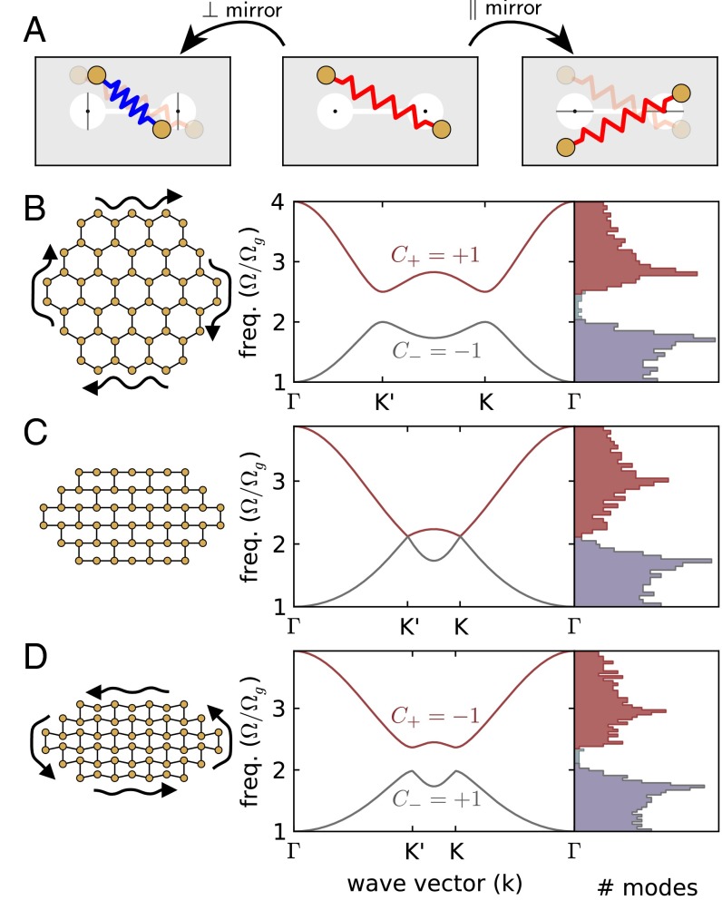
The geometric origin of the time-reversal symmetry breaking can also be seen in the case of gyroscopes connected by springs, by considering the energy of two connected gyroscopes. In the linearized limit, the stretching/compression of the spring is given by . If we mirror each gyroscope in the y axis ( or ), in general the spring length will be unchanged only if (i.e., if the mirror axis aligns with the equilibrium bond angle). However, if , or the mirroring axis is perpendicular to the bond, then the spring energy, , is conserved by converting stretching to compression (Fig. 4A). When considering an entire lattice, we see that for arbitrary displacements the bond energy will be conserved under time reversal if (and only if) we are able to choose a global mirror axis to which all bonds are either perpendicular or parallel. As a result, time-reversal invariance is only guaranteed for lattices composed of square or rectangular building blocks.
Fig. 4.
Controlling time-reversal invariance in a gyroscopic metamaterial. (A) The effect of mirroring a configuration of two gyroscopes around axes that are perpendicular or parallel to the equilibrium bond angle. Mirroring about axes that are perpendicular to the bond angle (Left) converts stretching to compression but conserves the energy stored in the bond. Mirroring about the axes that are parallel to the bond (Right) conserves the total bond length. Mirroring about other axes, in general, does not conserve energy. (B–D) For each lattice geometry (Left), the band structure for an infinite system is shown (Middle) along with the density of states for a finite lattice of 726 gyroscopes (Right). (B) An undisturbed, hexagonal honeycomb lattice. (C) A honeycomb lattice as it is distorted into a rectangular configuration while preserving the connectivity. (D) A honeycomb lattice distorted past the square configuration. The rectangular configuration has no band gap, and consequently no edge modes; as the lattice is further distorted the band gap reopens but the edge modes have opposite chirality.
It is instructive to note that, in the limit that gyroscopes are coupled by weak springs, our gyroscopic metamaterial has a well-known quantum-mechanical analog: the Haldane model of an electronic system in a honeycomb lattice (see Supporting Information and Figs. S7 and S8 for details) (26). In the Haldane model, time-reversal symmetry is broken by a staggered magnetic field. This field can be varied, resulting in a change in the topological character of the modes as quantified by the Chern number (12, 27, 28). Accordingly, depending on the strength of the field and asymmetry between the two sites in the unit cell, the Chern number of the bottom band is , and in the top band. A Chern number of zero indicates a trivial topology (a normal insulator), whereas a nonzero Chern number indicates a nontrivial topology. Whenever , topological edge modes appear in the gap between the two bands; the chirality and direction of propagation of these modes depends on the sign of the Chern number for lower band.
Fig. S7.
The two basis wave functions for near the Dirac point at , as a function of displacement from the Dirac point: . The bases are generated by starting with an arbitrary wave function in a unit cell (indicated with the shaded hexagon), and then repeating the wave function periodically, with wave-vector-induced phase factors. A and B show wave functions with angular momenta of +1 and −1 around the hexagon, respectively, as indicated with the red arrows.
Fig. S8.
Phase shifts for next-nearest-neighbor hoppings. Although these phase shifts are equal for a hexagon, distorting the lattice will make the phase shifts nonuniform. In general, adding diagonal hopping terms (dotted arrows) opens gaps at the Dirac points.
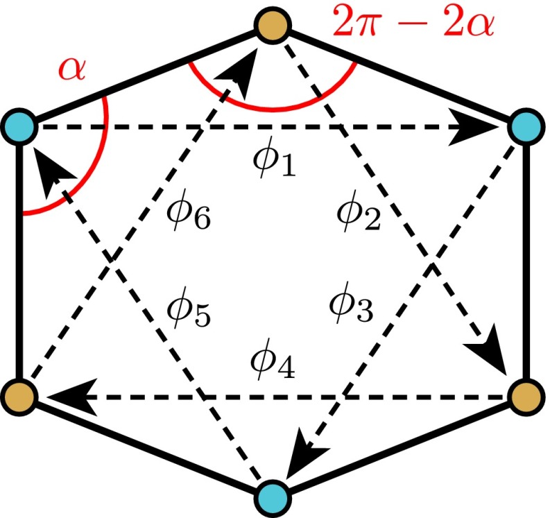
In gyroscopic metamaterials, the analog to changing the magnetic field is to geometrically distort the lattice. In either case, the relevant operation produces a phase shift in the hopping between neighboring sites; in the gyroscope system this phase shift is determined by the bond angles, . In the case of an undistorted honeycomb lattice, the modes have a Chern number of , in agreement with the Haldane model.
In a honeycomb lattice, it is possible to distort the constituent hexagons without changing the bond length (Fig. 4 B–D), allowing us to change the gyroscopic phase between neighboring sites without changing the network connectivity. As predicted by the time-reversal analysis above, the band-gap and chiral edge modes disappear when the bonds fall on a rectangular grid (in which case ). Furthermore, the dispersion relationship of an infinite gyroscopic lattice in this configuration has Dirac points at the corners of the Brillouin zone (Fig. 4C); this is topologically equivalent to the dispersion relationship of a honeycomb network of springs and masses. Continuing to distort the lattice past this point restores the band gap, but the edge modes now have opposite chirality, as reflected in an inversion of the bands and hence of the Chern number; . As a result, excitations along the edge now move in the other direction, opposite to the precession of individual gyroscopes. These effects can all be seen in Movies S4 and S5. Movie S4 shows the simulated dynamics of an edge mode in a spring coupled gyroscopic metamaterial as it is being distorted. Remarkably, this indicates the direction of the edge waveguide can be controlled purely through geometric distortions of the lattice, analogous to an effect recently observed in 1D acoustic phononic crystals (29).
We have presented an experimental proof of concept and theoretical analysis of a topologically protected unidirectional waveguide in a real mechanical metamaterial. The origin of our topological edge modes is due to time-reversal symmetry breaking; our analysis indicates this arises from the combination of the chiral nature of the gyroscopes and the geometry of the underlying lattice. Because the direction of the edge modes can be changed discontinuously with geometric distortions, in principle small displacements should be capable of inverting the edge mode direction. This mechanism may have practical applications for creating direction-tunable materials, but it also suggests interesting nonlinear effects should occur in the regime near the mechanically induced topological phase transition.
The prototypical gyroscopic solids we have developed here are examples of active metamaterials: Their design relies on the presence of internal motors that keep each gyroscope in a fast spinning state. An open challenge is to construct scalable gyroscopic metamaterials using nanofabrication techniques (e.g., microelectromechanical systems) or active molecules that convert chemical energy into rotation very much like the motors powering each gyroscope (30, 31). Such an implementation would pave the way toward realizing materials that support, at a microscopic scale, robust topological acoustic modes.
Note Added in Proof.
In the concluding stages of the present work, we became aware of a parallel independent effort in which a class of topological gyroscopic metamaterials was theoretically analyzed (32).
Equation of Motion
If a gyroscope is spinning with a large constant angular frequency, ω, around its principal axis, , then its dynamics are determined primarily by effect that forces have on its angular momentum. If the gyroscope axis is pivoted at one end and is subject to a force, at a position from the pivot as illustrated in Fig. 1 of the main text, then the gyroscope feels a torque . The resulting motion is
| [S1] |
For small displacements from the vertical () axis (small tilts), the z-component of is changed only to second order. Thus, the orientation of the gyroscope can be represented by a complex number, .
When a gyroscope is subject to a restoring force (e.g., gravity), , it will precess in a circular orbit at frequency . For gyroscopes subject to a gravitational force, the effective spring constant is , producing a precession frequency of , where is the distance from the fixed end to the center of mass.
Linearized Equation of Motion
To find the linearized equation of motion, we consider first an interaction of two gyroscopes p and q, with p being at the origin and q a distance a from p at an angle , as illustrated in Fig. S1.
Fig. S1.
A figure illustrating the process of finding the parallel and perpendicular components of displacements to a bond of length a between points p and q.
The effective spring constant for the interaction is given by the gradient of the force. In general, these gradients may be asymmetric in the components that are parallel and perpendicular to vector from the bond, which is defined as the line connecting points p and q. In the case of a linear spring with constant , for example, the spring constant for displacements along the bond is whereas the spring constant for displacements perpendicular to the bond is 0.
As an illustration, we now consider the linearized equation of motion for gyroscopes p and q interacting via this linear spring. In this case, we need only to find the displacement parallel to the bond () and multiply it by the spring constant to find the linearized force. We may write the unit vector from p to q as in complex form. The parallel component can be found by first rotating the bond to the x axis, taking the real part of (illustrated in Fig. S1) and rotating the bond back to its original position; the resulting force in complex form is given by
| [S2] |
| [S3] |
For a lattice, there is a sum over the nearest neighbors of each gyroscope and the equation of motion becomes
| [S4] |
where and the cross-product from Eq. S1 has resulted in the imaginary coefficient on the left hand side of Eq. S4.
For a general radial interaction force, (e.g., magnetically coupled gyroscopes), the equilibrium positions can result from the cancellation of opposing forces instead of the absence of forces. In this case, we obtain the following equation of motion:
| [S5] |
where . For a radially symmetric potential of the form , this results in and , where a is the separation between the two lattice sites.
In our experiment, the gyroscopes are coupled through small magnets. The force can be approximated by treating each gyroscope as a magnetic dipole with strength M; this produces an radial force between the gyroscopes plus an antirestoring torque from the magnetic interaction. The total effective force gradients are given by
| [S6] |
where is the magnetic characteristic spring constant, corresponding to a gyroscope precession frequency of , and we have converted torques between the magnetic dipoles to equivalent forces that depend on the ratio of lattice spacing (a) to pendulum length ().
In a honeycomb lattice, the symmetry of the lattice allows for the equations of motion to be simplified to
| [S7] |
where and . Here we see that the magnetically coupled system is different from the spring-coupled lattice in two ways: The effective pinning frequency, is decreased, and there is an asymmetry between the and the terms.
The equation of motion for the magnets, Eq. S7, is nearly equivalent to the simple linear spring case, excepting the slight asymmetry between the ψ and terms. (Note that for springs, the pairwise force between the two sites is 0 at equilibrium, which results in and and recovers a simpler equation of motion, Eq. S4.) The asymmetry of these terms has an interesting effect when viewed from the perspective of time-reversal symmetry breaking: The terms couple forward and backward propagating modes, and so when the symmetry breaking terms are relatively stronger. As a result there is a wider band gap for the magnetically coupled gyroscopes in comparison with those coupled by linear springs.
Experimental Details
The gyroscopic metamaterial was constructed from 54 hanging gyroscopes, as shown in Fig. S2. Each individual gyroscope consisted of a 3D printed cylindrical rotor (radius 10.4 mm) heat fitted to the shaft of a small (20 mm long) brushed dc pager motor. An N40 neodymium magnet (9-mm diameter, 4-mm thickness) was embedded with its moment aligned with the z axis in each rotor. The spinning mass of each gyroscope rotor was 6.1 g. The dipole moment of the magnets was determined from direct measurement of the force between attracting magnets (with dipole moments aligned) to be Am2. Each spinning mass was enclosed in a housing that was glued to the motor shaft and suspended by a weak spring. When the end of the gyroscope is displaced, the bending of the spring gives an effective pendulum length of mm.
The spacing between gyroscopes in the experimental lattice was 30.5 mm, corresponding to an effective spring constant that is roughly equivalent to the magnitude of the effective gravitational pinning spring, .
Fixed magnets (N52, 10-mm o.d., 5.5-mm i.d., 3 mm thick) were placed at the perimeter of the system in the position of each edge gyroscope’s missing neighbor. These fixed magnets were approximately two-thirds the strength of the inner magnets. We note that this detail is not crucial to the topological nature of the system. The strength of the boundary magnets does not change the frequencies of the gap edges (which depend on the bulk properties), and only slightly affects frequency distribution of modes within the gap.
We obtained the experimental normal modes for the frequency range Hz in frequency steps of 0.02 Hz. At each frequency, the system was excited at one lattice site for 80 s before recording began and subsequently recorded at the excitation frequency for 100 s. We found the elliptical orbits for each gyroscope using the Fourier transforms of the position vs. time data.
Linearity of the Magnetically Coupled System
It has been shown experimentally that lattices of interacting magnets can exhibit nonlinear behavior when excited at sufficiently large amplitudes (33). To ensure that our experiments were performed in a regime where linear analysis can be applied, we tested for the presence of nonlinear effects with three experiments that are summarized here and listed in detail below. (i) We characterized the shift in the normal mode frequencies of a pair of interacting gyroscopes as a function of the excitation amplitude. (ii) We verified that the frequency of an edge mode in our system of 54 interacting gyroscopes does not shift significantly as the amplitude of excitation was changed. (iii) We measured speed of the wave packet shown in Movie S1 and verified that the change in amplitude does not significantly affect the average speed of the wave packet. Our measurements of the effects of nonlinearities (detailed below) cover a range of excitation amplitude beyond the maximum excitation amplitude in the experiments of the main text.
-
i)
Fig. S3 shows the measured normal mode frequencies of a pair of interacting gyroscopes, each with two neighboring boundary magnets in a honeycomb configuration (as described in Experimental Details). Two normal mode frequencies are expected: a lower frequency mode in which the gyroscopes precess in phase (red dots in Fig. S3) and a higher frequency mode in which the gyroscopes precess out of phase (green dots in Fig. S3). The frequencies of both modes were tracked as the amplitude of an excitation damped during an interaction. The nonlinearity of the interaction is apparent because the mode frequencies are not constant with amplitude. However, at the upper limit of excitation amplitude of the experiments presented in the main text (3 mm), the deviations of the frequency are not appreciable. At this amplitude, a frequency shift of only less than 2% was observed for either of the modes. We note that the frequency shift reaches a maximum of 5% for the antisymmetric mode when the excitation amplitude reaches 4 mm.
-
ii)
The frequency shift of a gap mode was measured at varying excitation amplitudes. For each test a region of 0.06 Hz was tested near a known peak, and each frequency was excited for 80 s before recording and subsequently recorded for 100 s, as described previously. We determined that for changes in excitation amplitude ranging from 1.2 to 4.0 mm, the shift in frequency was less than 0.02 Hz. An example of the effect is shown in Fig. S5B. The frequencies for the fourth mode number are plotted for three amplitudes in the range indicated above.
-
iii)
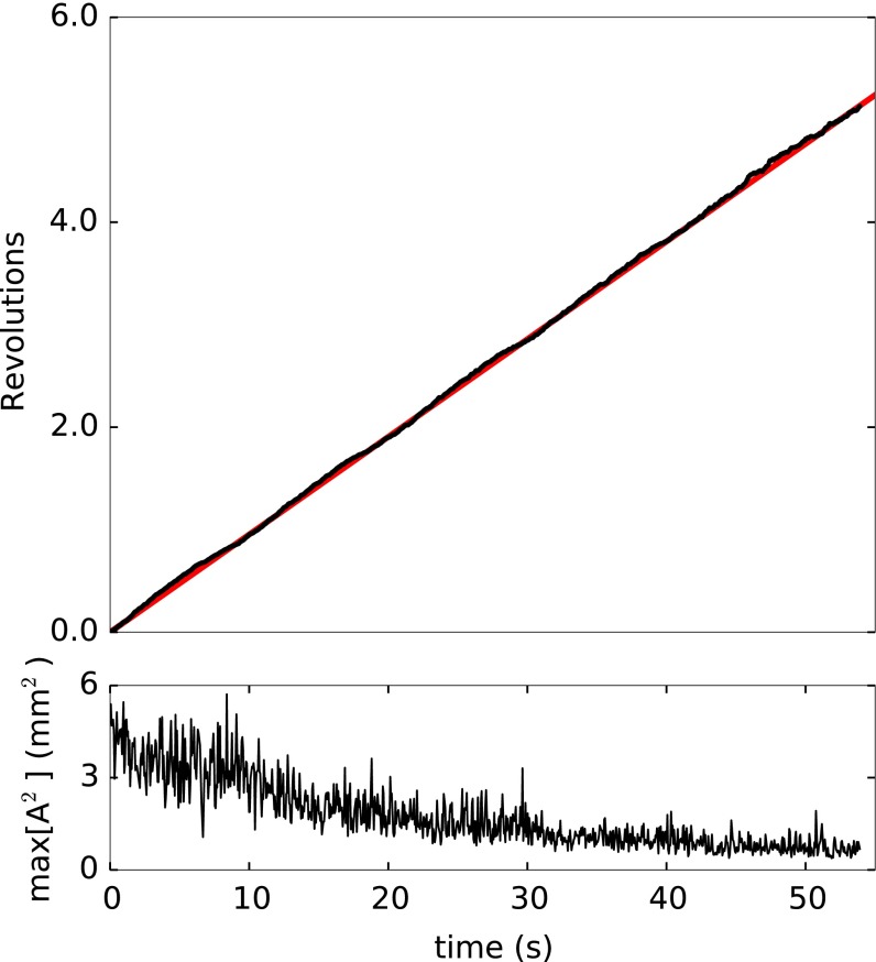
We tracked the position of the edge mode wave packet shown in Fig. S4 and Movie S1 as the amplitude of oscillation decayed. The position of the wave packet was found in each frame using a center-of-mass method, in which each lattice point was weighted by the squared displacement of its gyroscope. As shown in Fig. S4, the average speed of the wave packet is unaffected by the gradual decay in amplitude.
Fig. S4.
The position of a wave packet vs. time (Top) and the total oscillation amplitude squared as a function of time (Bottom). The time to travel around the boundary of the metamaterial stays constant as the amplitude of oscillation decays.
Furthermore, we do not observe mode mixing at the amplitudes of the data presented in this work.
Normal Mode Analysis
For second-order mass and spring systems with n lattice sites in two dimensions, we find the normal modes by considering the system of equations
| [S8] |
where a vector of dimension containing the x and y displacements of each mass in the network and K is a coupling matrix between sites. The normal modes are found by finding the eigenvalues, , and eigenvectors, , of the matrix:
| [S9] |
To find the normal modes of a finite system of gyroscopes we consider the linearized equations of motion, Eq. S5. As with the spring and mass system, these equations of motion can be expressed as a matrix:
| [S10] |
where again has dimension ; the basis states are of the form . The normal modes are given by the eigenvalues and eigenvectors of the matrix:
| [S11] |
To accurately model the experimental system, we included the effects of the weaker boundary magnets. First, an energy minimization was performed on a honeycomb lattice with 54 magnetically interacting points surrounded by weaker boundary magnets as described in Experimental Details. The energy minimization gave the equilibrium points that were used in the finite-system normal mode calculation. The spring constant between gyroscopes was given by , where r was the separation between interacting gyroscopes. The mode frequencies were calculated by assuming coupling of individual gyroscopes with all gyroscopes in the lattice as well as with only nearest-neighbor coupling.
A comparison between the expected gap modes from the model and the measured edge modes in the experiment is shown in Fig. S5. The shaded regions indicate the range of possible gap mode frequencies calculated with the measured experimental values A and mm. The red shaded region was calculated with entire lattice coupling, and the blue region was calculated with only nearest-neighbor coupling. The diamonds in Fig. S5 were calculated with entire lattice coupling and model parameters Am2 and mm.
We note that disorder (numerical and experimental) can greatly alter mode profiles. We find that experimentally observed mode profiles are qualitatively similar to numerically calculated mode profiles in a system with random disorder, as shown in Fig. S6.
Time Domain Simulation
We simulate a 2D gyromaterial in the time domain only for the case of spring interactions with free boundary conditions. We numerically integrate Eq. S1 considering a spring interaction and gravity. We consider only the x and y displacements and integrate using a fourth order Runge–Kutta method.
Band Structure and Chern Number Calculation
We find the band structure for both the spring and magnetically coupled systems on a honeycomb lattice using the linearized equations of motion, and assuming the solutions
| [S12] |
| [S13] |
where a and b refer to the two sites in each unit cell.
The resulting equations can be expressed as a matrix that is a function of the wave vector, . (For a 2D lattice the dimension of this matrix will be , where n is the number of lattice sites per unit cell.) The four eigenvalues of this matrix give the values of the four dispersion bands at a particular value of . These dispersion bands correspond to the frequencies obtained from the finite normal mode analysis. At each value of , each band has a corresponding eigenvector, , which corresponds to the amplitudes of the clockwise and counterclockwise rotating modes on the two lattice sites at that particular value of .
The Chern number of each band is given by an integral of the Berry curvature :
| [S14] |
where . In this work, Chern numbers are calculated numerically using a phase invariant formula (27):
| [S15] |
where is the “projection matrix” defined as , and is the wedge product.
Mapping to the Haldane Model
Our experiment is performed in the regime where . However, it is interesting to note that in the weak spring limit, , our system reduces to the Haldane model (26). In this limit, the equations can be simplified considerably and are amenable to analytical treatment. In particular, the Chern number can be determined analytically as a function of the angle in the honeycomb lattice deformation.
In the weak spring limit, the motion of each gyroscope is approximately circular, so there is only one degree of freedom per gyroscope. This can be seen by splitting the displacement of the gyroscope two polarizations, , where is the amplitude of precession in the direction determined by gravity, is the counter rotating amplitude, and is the frequency of precession for the mode. Because , the gravitational precession direction dominates () and all mode precession frequencies, , differ only slightly from .
Substituting this form of ψ into the linearized equation of motion and matching the coefficients of the exponentials gives
| [S16] |
| [S17] |
Perturbation theory can be used to find an equation for the u’s alone, which is equivalent to Haldane’s model of the quantum Hall effect. Because , Eq. S17 implies . Substituting this in Eq. S16 gives
| [S18] |
where is the angle between the bonds and , and the second-to-last sum is over all pairs of neighbors m and of n, and the last sum is over all neighbors m of n and neighbors l of m.
If one expresses the right side as , then finding the normal modes is the same as finding the band structure of electrons on a lattice with hopping amplitudes between the sites of the lattice. (The large value of implies that the polarization of the normal mode is circular, so it is defined just by a single phase and magnitude. Likewise, the wave function of an electron on a site is represented by a complex number that is also represented by a phase and amplitude.) Owing to the complex exponential term in Eq. S18, the bond angles lead to a phase shift between next-nearest neighbors on the lattice, similar to the phase shift on hopping terms from moving in a magnetic field. For the honeycomb lattice this differs from Haldane’s model only in that the second neighbor term has a real part.
The topological character of Haldane’s system can be quantified by calculation of the Chern number, which is an integral of the Berry curvature over the Brillouin zone of the lattice. A nonzero Chern number indicates a topologically nontrivial state and implies the existence of chiral edge currents. Systems with time-reversal symmetry must have a Chern number equal to zero, because time-reversal symmetry implies zero Berry curvature. However, not all systems with broken time-reversal symmetry must have a nonzero Chern number. In general, two bands separated by a finite gap will not acquire nonzero Chern number because of infinitesimal perturbations.
However, an infinitesimal perturbation can produce a large change in Berry curvature at Dirac points. Therefore, even the small complex phase terms in the Haldane model and in Eq. S18 can open a gap and induce a nonzero Chern number.
To see this effect mathematically, one can expand in powers of displacement from the Dirac point, (where is the wavevector of the Dirac point). Then the hopping matrix, T, can be written in terms of Pauli matrices. For a system without next-nearest-neighbor coupling, we find that after rotating the wavevector, , the Hamiltonian can be written as . The Berry curvature of the two bands near this point are both zero. Terms with complex phases break the degeneracy between the two states, which can be represented by adding a term , where is an effective mass. Even if is small, this changes the Berry curvature very close to the Dirac point, so that the net curvature in the bottom band in the vicinity of the Dirac point is , and the band above the Dirac point has opposite curvature.
For the honeycomb lattice there are only two sites per unit cell, so there are two modes with each wave number. A basis can be obtained by defining on one of the two sites and 0 on the other, and translating to other unit cells while multiplying by (Fig. S7). The degeneracy points are at , where a is the edge length of the hexagon; Fig. S7 shows the two basis states near .
Let us focus on just the leading terms of Eq. S18 and the terms that arise from hopping along the diagonals (next-nearest neighbors, ; see Fig. S8), because these are the terms that produce a gap. The matrix for the hopping along the sides is, to lowest order in , , where is the nearest-neighbor hopping amplitude. To understand the contribution from the next-nearest-neighbor hopping, we set . As shown in Fig. S7, the two basis wave functions now resemble vortices circulating around the hexagons in opposite directions.
Both wave functions pick up the same phase under translation, but they transform oppositely under rotation. Because the phase differences are different, the energies (i.e., frequencies of the normal modes in the gyroscope system) of the states are different; the one whose phase shifts match the phase of the hopping better has the lower energy (i.e., the energies are and , where and for the r next-nearest neighbors).
If we include the energy splitting and the linear terms in , we have
| [S19] |
where the top sign refers to the Dirac point we have been considering and the bottom sign is for the other one. If the phase shifts have twofold symmetry (i.e., ), we can simplify the effective mass to .
The total Berry curvature for each of the two Dirac points is . As a result, the Chern number of the top/bottom band is given by: .
In general, distorting the honeycomb lattice produces different phase shifts along different diagonals (Fig. S8). For a distorted honeycomb lattice, there are four angles of the hexagon equal to α and two equal to . The phases are twice this; thus, the Berry curvature near each Dirac point is . This curvature, and hence the Chern number, switch sign when the hexagon is distorted into a rectangle, in agreement with the analysis in the main text.
Supplementary Material
Acknowledgments
We acknowledge the Materials Research and Engineering Centers (MRSEC) Shared Facilities at The University of Chicago for the use of their instruments. This work was supported by the National Science Foundation MRSEC Program at The University of Chicago (Grant DMR-1420709). W.T.M.I. acknowledges support from the A. P. Sloan Foundation through a Sloan Fellowship and the Packard Foundation through a Packard Fellowship.
Footnotes
The authors declare no conflict of interest.
This article is a PNAS Direct Submission.
This article contains supporting information online at www.pnas.org/lookup/suppl/doi:10.1073/pnas.1507413112/-/DCSupplemental.
References
- 1.Maxwell JC. On the calculation of the equilibrium and stiffness of frames. The London, Edinburgh, and Dublin Philosophical Magazine and Journal of Science. 1864;27(182):294–299. [Google Scholar]
- 2.Wei ZY, Guo ZV, Dudte L, Liang HY, Mahadevan L. Geometric mechanics of periodic pleated origami. Phys Rev Lett. 2013;110(21):215501. doi: 10.1103/PhysRevLett.110.215501. [DOI] [PubMed] [Google Scholar]
- 3.Thorpe MF. Continuous deformations in random networks. J Non-Cryst Solids. 1983;57(3):355–370. [Google Scholar]
- 4.Wyart M, Nagel SR, Witten TA. Geometric origin of excess low-frequency vibrational modes in weakly connected amorphous solids. Europhys Lett. 2005;72(3):486–492. [Google Scholar]
- 5.Lubensky TC, Kane CL, Mao X, Souslov A, Sun K. Phonons and elasticity in critically coordinated lattices. Rep Prog Phys. 2015;78(7):073901. doi: 10.1088/0034-4885/78/7/073901. [DOI] [PubMed] [Google Scholar]
- 6.Kang SH, et al. Complex ordered patterns in mechanical instability induced geometrically frustrated triangular cellular structures. Phys Rev Lett. 2014;112(9):098701. doi: 10.1103/PhysRevLett.112.098701. [DOI] [PubMed] [Google Scholar]
- 7.Kane CL, Lubensky TC. Topological boundary modes in isostatic lattices. Nat Phys. 2013;10(1):39–45. [Google Scholar]
- 8. Paulose J, Chen BG-g, Vitelli V (2015) Topological modes bound to dislocations in mechanical metamaterials. Nat Phys 11(2):153–156.
- 9.Chen BG, Upadhyaya N, Vitelli V. Nonlinear conduction via solitons in a topological mechanical insulator. Proc Natl Acad Sci USA. 2014;111(36):13004–13009. doi: 10.1073/pnas.1405969111. [DOI] [PMC free article] [PubMed] [Google Scholar]
- 10.Paulose J, Meeussen AS, Vitelli V. Selective buckling via states of self-stress in topological metamaterials. Proc Natl Acad Sci USA. 2015;112(25):7639–7644. doi: 10.1073/pnas.1502939112. [DOI] [PMC free article] [PubMed] [Google Scholar]
- 11. Vitelli V, Upadhyaya N, Chen BG-g (2014) Topological mechanisms as classical spinor fields. arXiv:1407.2890 [cond-mat.soft]
- 12.Hasan MZ, Kane CL. Colloquium: Topological insulators. Rev Mod Phys. 2010;82(4):3045–3067. [Google Scholar]
- 13.Prodan E, Prodan C. Topological phonon modes and their role in dynamic instability of microtubules. Phys Rev Lett. 2009;103(24):248101. doi: 10.1103/PhysRevLett.103.248101. [DOI] [PubMed] [Google Scholar]
- 14.Wang Z, Chong Y, Joannopoulos JD, Soljacić M. Observation of unidirectional backscattering-immune topological electromagnetic states. Nature. 2009;461(7265):772–775. doi: 10.1038/nature08293. [DOI] [PubMed] [Google Scholar]
- 15.Berg N, Joel K, Koolyk M, Prodan E. Topological phonon modes in filamentary structures. Phys Rev E Stat Nonlin Soft Matter Phys. 2011;83(2 Pt 1):021913. doi: 10.1103/PhysRevE.83.021913. [DOI] [PubMed] [Google Scholar]
- 16.Yang Z, et al. Topological acoustics. Phys Rev Lett. 2015;114(11):114301. doi: 10.1103/PhysRevLett.114.114301. [DOI] [PubMed] [Google Scholar]
- 17.Hafezi M, Mittal S, Fan J, Migdall A, Taylor JM. Imaging topological edge states in silicon photonics. Nat Photonics. 2013;7(12):1001–1005. [Google Scholar]
- 18.Rechtsman MC, et al. Photonic Floquet topological insulators. Nature. 2013;496(7444):196–200. doi: 10.1038/nature12066. [DOI] [PubMed] [Google Scholar]
- 19.Süsstrunk R, Huber SD. PHYSICS. Observation of phononic helical edge states in a mechanical topological insulator. Science. 2015;349(6243):47–50. doi: 10.1126/science.aab0239. [DOI] [PubMed] [Google Scholar]
- 20.Peano V, Brendel C, Schmidt M, Marquardt F. Topological phases of sound and light. Phys Rev X. 2015;5(3):031011. [Google Scholar]
- 21.Ningyuan J, Owens C, Sommer A, Schuster D, Simon J. Time- and site-resolved dynamics in a topological circuit. Phys Rev X. 2015;5(2):021031. [Google Scholar]
- 22.Haldane FDM, Raghu S. Possible realization of directional optical waveguides in photonic crystals with broken time-reversal symmetry. Phys Rev Lett. 2008;100(1):013904. doi: 10.1103/PhysRevLett.100.013904. [DOI] [PubMed] [Google Scholar]
- 23.Raghu S, Haldane F. Analogs of quantum-hall-effect edge states in photonic crystals. Phys Rev A. 2008;78(3):033834. [Google Scholar]
- 24.Wang Z, Chong YD, Joannopoulos JD, Soljacić M. Reflection-free one-way edge modes in a gyromagnetic photonic crystal. Phys Rev Lett. 2008;100(1):013905. doi: 10.1103/PhysRevLett.100.013905. [DOI] [PubMed] [Google Scholar]
- 25.Maradudin AA. Some effects of point defects on the vibrations of crystal lattices. Reports on Progress in Physics. 1965;28(1):331–380. [Google Scholar]
- 26.Haldane FD. Model for a quantum Hall effect without Landau levels: Condensed-matter realization of the “parity anomaly”. Phys Rev Lett. 1988;61(18):2015–2018. doi: 10.1103/PhysRevLett.61.2015. [DOI] [PubMed] [Google Scholar]
- 27.Avron JE, Seiler R, Simon B. Homotopy and quantization in condensed matter physics. Phys Rev Lett. 1983;51(1):51–53. [Google Scholar]
- 28.Thouless DJ, Kohmoto M, Nightingale MP, den Nijs M. Quantized hall conductance in a two-dimensional periodic potential. Phys Rev Lett. 1982;49(6):405–408. [Google Scholar]
- 29.Xiao M, et al. Geometric phase and band inversion in periodic acoustic systems. Nat Phys. 2015;11(3):240–244. [Google Scholar]
- 30.Prost J, Jülicher F, Joanny JF. Active gel physics. Nat Phys. 2015;11(2):111–117. [Google Scholar]
- 31.Palacci J, Sacanna S, Steinberg AP, Pine DJ, Chaikin PM. Living crystals of light-activated colloidal surfers. Science. 2013;339(6122):936–940. doi: 10.1126/science.1230020. [DOI] [PubMed] [Google Scholar]
- 32.Wang P, Lu L, Bertoldi K. Topological phononic crystals with one-way elastic edge waves. Phys Rev Lett. 2015;115:104302. doi: 10.1103/PhysRevLett.115.104302. [DOI] [PubMed] [Google Scholar]
- 33.Molerón M, Leonard A, Daraio C. Solitary waves in a chain of repelling magnets. J Appl Phys. 2014;115(18):184901. [Google Scholar]
Associated Data
This section collects any data citations, data availability statements, or supplementary materials included in this article.


