

Abstract
An ideal myoelectric prosthetic hand should have the ability to continuously morph between any posture like an anatomical hand. This paper describes the design and validation of a morphing myoelectric hand controller based on principal component analysis of human grasping. The controller commands continuously morphing hand postures including functional grasps using between two and four surface electromyography (EMG) electrodes pairs. Four unique maps were developed to transform the EMG control signals in the principal component domain. A preliminary validation experiment was performed by 10 nonamputee subjects to determine the map with highest performance. The subjects used the myoelectric controller to morph a virtual hand between functional grasps in a series of randomized trials. The number of joints controlled accurately was evaluated to characterize the performance of each map. Additional metrics were studied including completion rate, time to completion, and path efficiency. The highest performing map controlled over 13 out of 15 joints accurately.
Index Terms: Biomechatronics, electromyography (EMG), myoelectric control, principal component analysis, transradial prosthesis
I. Introduction
An ideal myoelectric prosthetic hand should have the ability to continuously morph between postures like an anatomical hand. It requires a mechatronic design with actuated joints and a control system using electromyographic (EMG) signals to command motion. Multifunctional prosthetic hands contain high degrees of actuation (DOAs, i.e., motors) and even higher degrees of motion (DOMs, i.e., joints) which allow for many possible grasps and postures [1]–[3]. In fact, the mechanical design of many current multifunctional prostheses could drive the hand into the most important six functional postures required for activities of daily living [4]. However, the control systems implemented on these devices do not allow for this ability.
The inability to command a continuously morphing motion is due to the insufficient number of input command signals (EMG signals) compared to the number of output commands required (motor commands) [5], [6]. This challenge is effectively a multiple–input multiple–output (MIMO) problem. Santello et al. [7] showed that grasping is a “low dimensional” task. Santello et al. empirically derived the principal components (PCs) of human grasping (a mathematical coupling of joints in the hand). This specific mathematical coupling will be referred to as PCs throughout this study1. Santello et al. found that the first two PCs described over 80% of the variance in hand posture. PCs effectively reduce the dimensionality of the hand and thereby the number of input commands required to direct a hand posture. Our study tested the effect of the number of control inputs and the mapping of the control inputs on the ability to drive a continuously morphing virtual hand.
II. Background on Myoelectric Prosthetic Hands
The sensory and motor functions of the human hand comprise a complex and robust system capable of powerful grasps and fine manipulation. The musculoskeletal system of the hand consists of at least 18 joint articulations controlled by over 30 muscles [8]. The hand has proprioceptors that sense the position of the hand in space and sensory receptors capable of sensing temperature, vibration, shear, and movement [9]. The replacement of the human hand has challenged scientists, engineers, and prosthetists for decades [10]. Advances in micro-electronics, miniature-actuators, and battery technology have accelerated the number of developments in myoelectric prostheses. While these technologies have allowed for re-energized research in advanced mechanical and control system design, many popular commercially available prosthetic hands are still single degree of freedom (DOF, i.e., number of input control signals) devices [11]–[13]. The challenges of the MIMO problem have slowed the availability of advanced myoelectric control systems in commercially available prostheses. The following sections discuss the current state of the art in myoelectric control systems.
A. Proportional Control
The control of a single DOF or “open-close” prosthesis typically uses a direct control scheme that proportionally maps a control signal (i.e., EMG signals measured at a control site) to a single control variable (e.g., motor speed) [10], [14] [15]. Conventional proportional control requires little cognitive effort from the user, can occur with minimal computational delay, and the EMG measurement is robust since only two control sites are necessary. Many two-site myoelectric control systems are successfully utilized on the market today [11]–[13]. However, single DOF prostheses are limited to one grasping posture. Users indicate that multiple grasps and increased articulation are highly desirable design considerations [16], [17] and are not achievable when using proportional control on a single DOF prosthesis. Recently available multifunctional prosthetic hands have increased mechanical complexity that allows for multiple grasping postures but must be accompanied by a more advanced control scheme.
B. Pattern Recognition
Pattern recognition is a widely researched scheme for the control of multifunctional prosthetic hands [18]–[20]. It is based on measuring patterns of EMG signals and assigning each pattern to a specific posture/motion. The EMG measurement of multiple control sites is preprocessed and segmented into windows over time. Features are extracted from each window which contain information on the EMG signal. The classifier then decides upon the desired posture/motion from the extracted features. The pattern recognition system can recognize many patterns but must be trained for each pattern before use. The postures/motions are predefined and cannot vary during use. Pattern recognition provides a method for controlling multiple degrees of freedom but sacrifices flexibility.
C. State Machines
Another type of advanced myoelectric control scheme is based on state machines or event driven finite-state (EDFS) schemes [21]–[24]. There are several commercial devices that integrate simple state machines within the control scheme [1], [2]. Like pattern recognition, state machines can control multifunctional prostheses. State machines consist of many predefined states each with a unique function (i.e., posture) that can be selected sequentially. The input signal commands a transition between the states until the desired state is selected. Then, the predefined function is performed. State machine control methods demand memorization to iterate through the states. Also, the control scheme allows for only a limited, predefined set of functions. A state machine does not allow for variations on the set functions. The transition between states inherently slows the ability of the user to perform a task.
D. Mathematical Coupling Using Principal Components
The study of the principal components [7], [25], [26] of grasping has provided another method for the control of a myoelectric hand. Santello et al.. studied the principal components of nonamputee subjects when grasping everyday objects. The study concluded that two principal components describe over 80% of the variance in hand posture when grasping everyday objects. The first PC describes the flexion of the metacarpophalangeal (MCP) joint of the digits and the rotational/adduction of the thumb. The second PC describes the extension of the MCP joints and flexion of the proximal interphalangeal joint (PIP) of the digits while the thumb follows the same pattern as in the first PC. Fig. 1 depicts the two dimensional domain (referred to hereafter as the PC domain) and the coordinates of 57 different grasps tested in [7]. This result opened an intriguing method of control of multifunctional prosthetic hands since [7] has shown that grasping can be achieved with only two control signals.
Fig. 1.

The distribution of grasping postures in the principal component domain (PC domain) found by Santello et al., 1998. Santello et al. found that the first and second principal components (PC1 and PC2) accounted for more than 80% of the variance in the joint angles of grasping postures. Therefore mapping two control input signals to PC1 and PC2 provides a means to command a prosthetic hand into numerous grasping postures using just two control inputs. The four target postures used in this study are circled and shown. The target postures were chosen because they are evenly distributed between the four quadrants of the PC domain and constitute four of the six functional grasps described by [4]. The bimodal trend in the distribution of postures is shown by the dashed lines.
Ciocarlie and Allen [27] used mathematical coupling based on principal components in the control of advanced robotic hands. The reduced dimensionality of the control system allowed for computational advantages when interfacing between the human and robot. Ciocarlie and Allen focused on complex tasks like dexterous grasping and grasp stability which further demonstrates the utility of PCs in the control of multi-DOF hands. Matrone et al. [28]–[30] showed the efficacy of a control system for a myoelectric prosthetic hand based on PCs. In their work, PCs were derived in order to drive a six DOA prosthetic hand using only two input command signals and single map onto the PC domain. The experimental results proved the ability of this type of controller to drive a prosthetic hand into typical grasping postures using computer and myoelectric control.
The bimodal distribution of postures in the PC domain suggests that better (i.e., faster/more accurate) control might be achieved if the EMG inputs were aligned to the distribution. We tested this hypothesis by implementing novel transformations (maps) of the EMG signals on the PC domain [31]. The use of novel mappings motivated additional questions including the benefit of additional control sites (i.e., a two DOF mapping versus a four DOF mapping). The control system architecture is described in detail in Section III. The experimental methods are described in Section IV. The ability of the control system to drive a high DOM virtual hand into functional grasps in a continuously morphing fashion is validated and discussed in Section V.
III. Development of Controller Architecture
A block diagram of the controller architecture based on principal components is shown in Fig. 2. The EMG control signals are processed using standard EMG processing techniques. The PC domain maps transform the EMG signals into a PC coordinate (PC1, PC2). The joint angle transform produces an array of 15 joint angles from the PC coordinate which is then sent to the virtual hand model for visualization. It should be noted that the controller does not require any training unlike pattern recognition techniques. The following section describes the controller architecture in more detail.
Fig. 2.

Block diagram of the controller architecture based on principal components of human grasping. Raw EMG control signals are processed using standard EMG processing techniques. Four different PC domain maps are tested using various transformations of the EMG control signals on the PC domain. The output of the maps is a PC coordinate (PC1, PC2). The joint angle transform converts the PC coordinate into an array of 15 joint angles (2). The virtual hand visualizes the 15 joint angles in real time.
A. EMG Processing
The four EMG signals were acquired using ProControl2 electrode pairs (Motion Control, Inc.) and self-adhesive Ag/AgCl snap electrode stickers (Noraxon USA, Inc.). Electrodes were placed on flexor digitorum superficialis (EMG A), extensor digitorum (EMG B), extensor carpi ulnaris (EMG C), and flexor carpi ulnaris (EMG D). The location of the control sites were based on previous work [32] which found four independent surface EMG sites on the forearms of nonamputee subjects. The measured raw EMG signals from four control sites were amplified by the ProControl2 electrode and sent to a NI USB-6008 Data Acquisition (DAQ) device (National Instruments, Inc.). The raw analog EMG signal was sampled at 1 kHz. Then the signal was band pass filtered (30–450 Hz), notch filtered at 60 Hz, rectified, smoothed with a 200 ms moving average filter, and normalized individually to the signal input range of the DAQ. A tuning process was performed for each subject before the myoelectric sessions took place. The tuning process included adjusting the gain and activation threshold for all EMG signals in order to produce the most comfortable control system for each subject. The gains were adjusted to ensure that every task was achievable without overdue effort including co-contraction tasks (i.e., when postures lie far from the EMG signal axes in the PC domain). The activation thresholds were adjusted to negate quiescent EMG signals. All of the processing techniques described above are typical clinical practices and can be implemented when using many commercial prosthetic hands.
B. PC Domain Maps
The controller is based in the PC domain. Various maps between the EMG control signals and the PC domain were investigated. All maps as well as the target postures used in the experimental protocol are depicted in Fig. 3. The generalized equation of the mappings is described by (1). Table I specifies the unique transformation matrix [A] and offset vector [B] implemented by each map
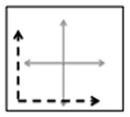
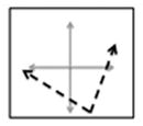
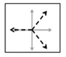
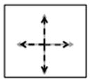
Fig. 3.

Maps 1–4 on the PC domain. Map 1 translates the EMG signals to the third quadrant and aligns EMG A with PC1 and EMG B with PC 2. Map 2 translates and rotates the EMG A and EMG B signals. The rotation mimics the bimodal pattern seen in the grasping posture distribution from Santello et al. Map 3 divides the PC domain into three equal portions using EMG A, B, and C. Map 4 divides the PC domain into four equal portions using EMG A, B, C, and D.
TABLE I.
Definitions of Maps 1–4
| Maps | Transformation Matrix - [A] | Offset Vector - [B] | |||
|---|---|---|---|---|---|
| 1 |
|
|
|
||
| 2 |
|
|
|
||
| 3 |
|
|
|
||
| 4 |
|
|
|
||
| (1) |
Map 1 only utilizes EMG A and B and projects the EMG control signals to the third quadrant of the PC domain. The EMG A and B axes correspond to the positive PC1 and PC2 directions, respectively. This map was considered to be the simplest method of maneuvering in the PC domain. Map 2 only utilizes EMG A and B as well. However, Map 2 projects the EMG control signals to the fourth quadrant of the PC domain. This map was developed to mimic the bimodal distribution of the postures in the PC domain (see dashed lines in Fig. 1). A set of vectors that best fit the distribution of postures in the PC-domain was derived using Principal Component Analysis and used as the transformation matrix [A] for map 2 (Table I). The vectors were then translated to ensure that the entire principal component domain was accessible using this map. Map 3 utilizes EMG A, B, and C and divides the PC domain into three equal portions. The EMG A axis is projected to the first quadrant of the PC domain. The EMG B axis projects onto the negative PC1 axis. The EMG C axis is projected to the fourth quadrant of the PC domain. Map 4 utilizes all four EMG signals (A, B, C, and D) and divides the principal component domain into four equal portions. The EMG A, B, C, and D axes follow the negative PC2 axis, negative PC1 axis, positive PC1 axis, and positive PC2 axis respectively.
For all mappings, EMG signals were assigned in order to follow the most physiologically realistic maps by applying the following rules: 1) flexor digitorum superficialis (EMG A) drives the hand to close; 2) extensor digitorum (EMG B) drives the hand to open; 3) extensor carpi ulnaris (EMG C) drives towards lateral prehension/zipper; 4) flexor carpi ulnaris (EMG D) drives towards power grasp/fry pan. In all cases, the result of the (1) is a PC coordinate (PC1, PC2) which is the input to the joint angle transform.
C. Joint Angle Transform
The joint angle transform converts the PC coordinate into a 15 element joint angle vector using a mathematical coupling based on the PCs of human grasping. Each principal component vector ( and ) is a 15-element vector describing a pattern of joint angles. The principal component vectors are derived from physiological human grasping data, as calculated by (7), and are the source of the biomimetic characteristics of this control algorithm. The linear combination of the two PC vectors and the PC coordinate (PC1, PC2) equals a joint angle command vector which controls the posture of the hand as described by
| (2) |
The control algorithm described by (2) converts the EMG input signals into a continuously variable joint angle command vector. In other words, the posture of the hand can continuously morph from posture to posture by varying the EMG control signals. It should be noted that the input to the joint angle transform (the PC coordinate) has two elements whereas the output of the transform (the joint angle vector) has 15 elements. The joint angle transform produces a dimensionality transformation between the PC domain and the joint angle domain. The mathematical coupling defined by the principal components of grasping enables this transformation to take place using biomimetic patterns. However, the resulting posture is also limited by this coupling. For example, the posture used when describing the number two (or the “peace” sign) cannot be accomplished using this controller since the mathematical coupling described by the principal components flexes all four digits in near unison. This controller is designed to command grasping postures and can achieve all the functional grasps, as shown in Fig. 1.
IV. Experimental Methods
A. Subject Information
An experimental protocol was developed to validate the performance of the controller and to determine a preferred map. Ten healthy, nonamputee subjects aged 22–58 were selected for the study. All experiments were conducted using the dominant arm (nine subjects were right-hand dominant and one was left-hand dominant). The study took place over a single three hour meeting in the Integrated Teaching and Learning Laboratory at the University of Colorado at Boulder for each subject. The Institutional Review Board at the University of Colorado at Boulder reviewed and approved the experimental protocol.
B. Experimental Protocol
The experiment was separated into three sessions. First, a joystick control session developed a performance benchmark for each subject using a Parallax two-axis joystick (DigiKey Corporation). Then a practice session where the subjects were first introduced to each map and posture using myoelectric control. The experimental session produced the dataset analyzed in Section V using myoelectric control.
Each session presented the subject with a randomized series of trials. The task was to match the controlled posture to the target posture in ten seconds or less. The subjects were provided instantaneous feedback on the number of joints controlled accurately through the testing interface. The feedback was produced by comparing the joint angle command vector [calculated in real time using (1) and (2)] and the target posture. The four target postures (lateral prehension—“zipper,” power grasp—“fry pan,” cylindrical prehension—“sugar cone,” and hand flat—“ashtray”) are shown in Fig. 1. These grasps were chosen because they are evenly distributed between the four quadrants of the PC domain and constitute four of the six functional grasps described by [4]. The target posture and the map used in each trial were varied for a total of 16 unique combinations. The target postures were randomized within each map. The order of the maps was randomized between subjects. The 10-s trial was followed by a 5-s break before the next trial. The joystick control session, practice session, and experimental session consisted of 16, 16, and 64 trials, respectively, for each subject as prescribed by a power analysis [33].
C. Testing Interface and Virtual Hand Model
The testing interface developed in Labview is shown in Fig. 4. The target posture is static image that varies across trials. The maximum accuracy score displays the highest number of joints controlled accurately at any time during the trial. The pause button allows the subject to pause the experiment at any time. The controlled posture morphs as the subject manipulates control signal. The current accuracy instantaneously displays the number of joints controlled accurately. The four normalized EMG waveforms are displayed in real time.
Fig. 4.

Testing interface seen by the subjects. Target posture is static image that varies across trials. Maximum accuracy score displays the highest number of joints controlled accurately at any time during the trial. Pause button allows the subject to pause the experiment at any time. Controlled posture morphs as the subject manipulates the control signals. Current accuracy instantaneously displays the number of joints controlled accurately throughout the trial. Two-four normalized EMG waveforms are displayed in real time.
The custom-built, virtual hand model can be controlled using a variety of interfaces (joystick, EMG, computer mouse, etc.). The model has 15 articulating joints corresponding to the 15 joints measured in [7] and is further described in Table II. All 15 joints can be manipulated in real time. Joint angle limits corresponding to their anatomical range of motion were developed in order to disallow nonanthropomorphic motions [34]. The hand dimensions and joint ranges of motion (ROM) are modeled after a 50% percentile male hand [34]. The thumb joint locations and axes of rotation were based upon anthropometric data and modeling studies of the thumb [35], [36].
TABLE II.
Joints of the Virtual Hand Model. Virtual Hand Model was Based on a 50th Percentile Male Hand and the Joints Match Those Studied by [7]
| Joint Number | Joint Name | Joint Abbreviation | Joint Description | Range of Motion (degrees) |
|---|---|---|---|---|
| 1. | Thumb Rotation | TR | Rotation about CMC joint | 180 |
| 2. | Thumb MCP | TM | Flexion about length of thumb | 90 |
| 3. | Thumb PIP | TP | Flexion about length of thumb | 90 |
| 4. | Thumb Abduction | TA | Abducts towards palm | 90 |
| 5. | Index MCP | IM | Flexion about length of digit | 90 |
| 6. | Middle MCP | MM | Flexion about length of digit | 90 |
| 7. | Ring MCP | RM | Flexion about length of digit | 90 |
| 8. | Little MCP | LM | Flexion about length of digit | 90 |
| 9. | Index PIP | IP | Flexion about length of digit | 90 |
| 10. | Middle PIP | MP | Flexion about length of digit | 90 |
| 11. | Ring PIP | RP | Flexion about length of digit | 90 |
| 12. | Little PIP | LP | Flexion about length of digit | 90 |
| 13. | Index Abduction | IA | Abducts away from middle | 30 |
| 14. | Ring Abduction | RA | Abducts away from middle | 30 |
| 15. | Little Abduction | LA | Abducts away from middle | 30 |
D. Metrics
Several metrics were used to study the performance of each subject. All the metrics were based on the postural envelope. The postural envelope was defined as 25% of the total range of motion of each joint [23]. If a commanded joint angle was within the postural envelope, then that joint was considered to be controlled accurately. The number of joints controlled was defined as the maximum number of joints (out of 15 possible joints) that were ever simultaneously within the postural envelope during the 10-s trial. The completion rate (CR) metric was defined as the number of successful trials per total number of trials. A successful trial was when all 15 joints were held in the postural envelope for 0.5 s. The time to completion (TC) metric measured the duration of the trial (in seconds) before a success occurred. Finally, the path efficiency (PE) metric was defined the measured rotational distance [denominator in (3)] compared to the shortest possible rotational distance [numerator in (3)] between the starting posture and the target posture to produce an efficiency measure between 0%–100%. The measured rotational distance was found by summing the difference in joint angle between sequential updates of the hand posture. The total number of updates (N) depended on the length of the trial in time
| (3) |
The various maps altered the distance between the EMG axes and the postures in the PC domain. A correlation analysis was performed to study the relationships between the distance between the EMG axes and the postures in the PC domain. The diagonal distance is defined as the distance between the origin and the posture (shown in Fig. 5 by dashed lines). The perpendicular distance is the distance between the posture and the closest point along any axis (shown in Fig. 5 by solid lines).
Fig. 5.

Example of diagonal and perpendicular distance definition using Map 2. Diagonal distance is measured from the origin of the map to the posture. The perpendicular distance is the shortest distance from the posture to the nearest axis. Amount of co-contraction necessary to acquire off axis target postures is quantified by the perpendicular distance metric.
MATLAB (The Mathworks, Inc.) was used to analyze the results. One way analysis of variance (ANOVA) tests and Tukey–Kramer comparisons were used to determine significance. The error bars in the figures represent one standard deviation. A least square fit line was used in the correlation analysis and was derived by minimizing the sum of the squared residuals. The goodness of fit (R2) measure describes the variance of the data about the least square fit line and was found by subtracting the ratio of the sum of squared residuals over the total sum of squares from one. The p-value describes the significance of the correlation and was considered statistically significant when having a value less than 0.05.
V. Experimental Results and Discussion
A. Joystick Control Versus Myoelectric Control
The number of joints controlled accurately for both myoelectric control and joystick control trials across maps for all subjects is compared in Fig. 6. There was not a significant difference between the performance of each control method within each map or across maps. This is an interesting finding since joystick control was developed to be a benchmark for the best possible performance. Joystick control provides independent, or co-activation free, command input signals as compared to EMG signals. Also, subjects using joystick control could command any PC coordinate free of bias to the location of the posture in the PC domain. In contrast, subjects had to co-contract in order to reach regions of the PC domain not close to an EMG axis when using myoelectric control. The results in Fig. 6 show that the bias in the PC domain introduced when using myoelectric control did not significantly change the performance when compared to joystick control. In other words, the use of myoelectric command signal is equally as effective as a joystick command signal in this experimental paradigm.
Fig. 6.

Number of joints controlled accurately for both myoelectric control and joystick control trials across maps and all subjects.
B. Highest Performing Map
The performance of all four maps for all metrics is displayed in Fig. 7. The maps respectively directed over 11, 13, 10, and 11 joints accurately. The completion rate for each map was over 21, 37, 21, and 14 percent, respectively. The performance of Map 2 was statistically more accurate (p < 0.05) and had a statistically higher completion rate than any of the other maps (p < 0.05). The seemingly low completion rates (less than 50%) are due to the complexity of the task. The subject must position all 15 joints into the postural envelope at the same time in order for a successful trial. These values were expected. The time to completion metric shows a similar trend in that Map 2 had the fastest average time to completion. However, Maps 3 and 4 tended to have the highest path efficiency measures. This result led to the correlation analysis discussed in Part C. In general, an increase number of control sites (Maps 3 and 4) do not increase performance using the postural controller.
Fig. 7.

Comparison of performance metrics over all maps. Performance of Map 2 was statistically greater than the other maps for both the number of joints controlled and completion rate metrics (p < 0.05).
The design of Map 2 stemmed from the bimodal distribution of postures in the PC domain (see Fig. 1). Santello et al. describe that the trends seen in the distribution of the postures in the PC domain “points to the possible existence of two main synergies through which hand shape is modulated.” Map 2 transforms the PC domain to align the two EMG control axes with these two main synergies. This transformation yielded the highest performing map. The other maps do not follow the distribution of postures in the PC domain and do not perform as well. This result motivates further investigation into the optimization of the projections of EMG input signals onto the PC domain for specific users.
C. Correlation Analysis of Distance Versus Performance
In light of the results described in Part B, we posit that having to co-contract to reach postures lying far from EMG control axes was more difficult to achieve and therefore would tend to bias our results. To test this hypothesis a correlation analysis was performed in order to determine if the diagonal and perpendicular distances from the EMG axes to the postures in the PC domain affected the performance of the controller (see Fig. 5). The scatter plots2 of the diagonal and perpendicular distances compared to each performance metric are shown in Fig. 8.
Fig. 8.

Correlation analysis between distance and all performance metrics. The four rows correspond to the four performance metrics [number of joints controlled, completion rate (CR), time to completion (TC), and path efficiency (PE)] and the two columns correspond to the two distance metrics (diagonal and perpendicular distance). The least square fit line, goodness of fit measure, and p-value are shown for all comparisons. Correlation between path efficiency (PE) and diagonal distance (circled) is the only relationship with a significant correlation. This finding mirrors the trend shown in Fig. 7 where PE was greatest for Maps 3 and 4 which have the shortest diagonal distances to all target postures.
The trends of the least square fit lines all show an inverse relationship between the performance and the Euclidian distance but only the correlation between path efficiency (PE) and the distance from the origin shows a statistically significant correlation (p < 0.05). This result mirrors the trend shown in Fig. 7 where the PE for Maps 3 and 4 were highest and have the shortest diagonal distances.
This finding does not substantiate the authors’ hypotheses that an increase in distance from the control axes makes the task more difficult to achieve. This finding suggest that subjects were able to use co-contraction to achieve the target postures readily enough and that co-contraction did not adversely affect their performance.
The correlation between PE and diagonal distance shows the greatest goodness of fit (R2) and is the only correlation of statistical significance (p < 0.05). This trend suggests that Maps 3 and 4 have greater PE because they have on average lower diagonal distances than Maps 1 and 2. The distance between the origin and the postures is shortened because the origin for Maps 3 and 4 is centered on the origin of the PC axes and therefore closer to the postures. The path efficiency metric describes the amount of “wandering” in the PC domain that the subject performs during a successful trial (3). The results suggest that the less wandering occurs when the required distance is shorter. This analysis also confirmed that the other performance metrics (accuracy, time to completion, and completion rate) were not significantly correlated to the diagonal or perpendicular distance metrics. The metrics measured performance independent of the location of the target posture in the PC domain.
D. Practice Session Versus Experimental Session
The average number of joints controlled accurately during the experimental session (11.7 ± 0.3) was significantly greater (p < 0.05) than during the practice session (10.5 ± 0.4) across all subjects. This result indicates a brief practice session (i.e., less than 10 min in duration) increases the performance of the subjects significantly. It should also be noted that the subjects were not provided any instruction as to how to best perform the task for each posture/map combination. The subjects were naïve to the map used in each trial and therefore were not able to learn strategies for how to accomplish each specific map/posture combination. This protocol forced the subjects to guess the function of each control site at the beginning of the trial before determining the best strategy. As shown in [30], the authors would expect that additional instruction would increase the performance of the subjects.
E. Future Development
Further development will be required in order to implement the controller on a physical prosthesis. This controller is a high level controller compared to low level controllers that function inside a motor control feedback loop. The goal of a high level controller is to decipher user intent and define the desired task. Low level controllers convert the output of the high level controller to motor commands. We anticipate implementing a low level position control system using a proportional-derivative (PD) architecture. A “time-out” function will be integrated into the low level controller. The “time-out” function will lock the system into the desired posture if that posture is held for a certain time period. We anticipate implementing these control schemes on a physical prosthesis and performing experimental trials to measure grasping metrics such as grasp stability.
Finally, the motivation for using the variety of number of DOFs and projections onto the PC domain has a larger goal. The authors plan to investigate postural control algorithms that can be optimized for an individual (i.e., maps tuned to a specific user). This study was focused on proving that certain maps provide benefit over others and therefore encouraging the pursuit of optimal maps for each user in the future.
VI. Conclusion
Our study verifies that a myoelectric controller based on principal components of human grasping can control a multi-multifunctional virtual hand in a continuously morphing fashion. A validation experiment studied the performance of the controller using clinically practiced techniques including myoelectric control site selection, commercially available surface electrodes, and standard EMG filtering. The map that mimicked the bimodal distribution of postures in the PC domain (Map 2) achieved the highest performance by directing over 13 joints accurately. A correlation analysis was performed in order to understand the relationship between distance in the PC domain and performance. The experimental results presented indicate that the controller based on PCA of human grasping provides an effective method for nonamputee subjects to morph a high DOM virtual hand into functional grasps.
Acknowledgments
This work was supported by the Department of Veterans Affairs, Rehabilitation Research and Development Service and was administered through the VA Eastern Colorado Healthcare System–Denver VAMC.
The authors would like to thank Dr. E. L. Secco for providing the empirical principal component matrix which allowed us to pursue this idea and Dr. C. Cipriani for his precious help.
Biographies
Jacob L. Segil (M′11) received the B.S. degree in mechanical engineering from the University of Illinois, Urbana-Champaign, IL, USA, in 2008, and the M.S. degree in mechanical engineering, in 2012, from the University of Colorado, Boulder, CO, USA, where he is currently pursuing the Ph.D. degree in mechanical engineering.
From 2008 to 2010, he was a Research Engineer in the Center for Bionic Medicine at the Rehabilitation Institute of Chicago (RIC). Currently, he is a Research Assistant in the Biomechatronics Development Laboratory at the University of Colorado Denver– Anschutz Medical Campus. His interests include mechatronic design and brain machine interfaces, in particular myoelectric control of prosthetic limbs

Richard F. ff. Weir (S′92–M′92) is Director of the Biomechatronics Development Laboratory at the University of Colorado Denver–Anschutz Medical Campus. He is also a Research Healthcare Scientist for the VA Eastern Colorado Healthcare System–Denver VAMC. In addition, he holds Research Associate Professor appointments in the Department of Bioengineering at the University of Colorado Denver–Anschutz Medical Campus. His research interests are in the area of mechanical design and control of artificial hand/arm replacements. His research covers all aspects of the problem ranging from neural control, mechatronics design and development, novel actuator technologies, and clinical deployment of these systems.
Footnotes
Depending on the field of research, the literature uses the terminology principal components, postural synergies, and eigengrasps to describe the mathematical coupling of joints in human hand. This study uses the term principal components in all cases.
Not all scatter plots contain the same number of datum. Missing datum are due to unsuccessful combinations of postures and maps across all subjects.
Contributor Information
Jacob L. Segil, Email: jacob.segil@colorado.edu, Department of Mechanical Engineering, University of Colorado at Boulder, Boulder, CO 80309 USA, and also with the Biomechatronics Development Laboratory, Department of Bioengineering, University of Colorado at Denver, Anschutz Medical Campus, Aurora, CO 80045 USA.
Richard F. ff. Weir, Email: richard.weir@ucdenver.edu, VA Eastern Colorado Healthcare System–Denver VAMC, Denver, CO 80220 USA, and also with the Department of Bioengineering, University of Colorado Denver, Anschutz Medical Campus, Aurora, CO 80045 USA.
References
- 1.ILIMB User Manual. Touch Bionics [Online] Available: http://www.touchbionics.com/media/58279/i-limb_digits_user_manual_ma01063.pdf.
- 2.Bebionic v2 Brochure. RSL Steeper [Online] Available: http://rslsteeper.com/uploads/files/159/bebionic-ukrow-product-brochure-rsllit294-issue-21.pdf.
- 3.Vincent Hand. Vincent Systems [Online] Available: http://hand-prothese.de/vincent-hand/
- 4.Keller A, Taylor C, Zahn V. Studies to determine the functional requirements for hand and arm prosthesis. Dept. Eng., Univ. California; Los Angeles, CA: Jul, 1947. [Google Scholar]
- 5.Parker P, Englehart K, Hudgins B. Myoelectric signal processing for control of powered limb prostheses. J Electromyogr Kinesiol. 2006 Dec;16(6):541–548. doi: 10.1016/j.jelekin.2006.08.006. [DOI] [PubMed] [Google Scholar]
- 6.Weir RF, Sensinger JW. Design of Artificial Arms and Hands for Prosthetic Applications. New York: McGraw-Hill; 2009. [Google Scholar]
- 7.Santello M, Flanders M, Soechting JF. Postural hand synergies for tool use. J Neurosci. 1998 Dec;18(23):10105–10115. doi: 10.1523/JNEUROSCI.18-23-10105.1998. [DOI] [PMC free article] [PubMed] [Google Scholar]
- 8.Moore KL, Dalley AF. Clinically Oriented Anatomy. 4. Philadelphia, NJ: Lippincott Williams Wilkins; 1999. [Google Scholar]
- 9.Silverthorn DU. Human Physiology: An Integrated Approach. 5. San Francisco, CA: Benjamin Cummings; 2009. [Google Scholar]
- 10.Childress DS. Powered limb prostheses: Their clinical significance. IEEE Trans Biomed Eng. 1973 May;20(3):200–207. [Google Scholar]
- 11.Hosmer Terminal Device Hosmer Prosthetics Orthotics. Online. Available: http://www.hosmer.com/products/hooks/pdfs/PR108-Hooks_Brochure.pdf.
- 12.Electric terminal device (ETD), Motion Control. Online. Available: http://www.utaharm.com/ETD-Sales-Sheet.pdf.
- 13.System Electric Hand. Ottobock; Online. Available: http://www.otto-bock.com/cps/rde/xchg/ob_us_en/hs.xsl/6952.html. [Google Scholar]
- 14.Dorcas D, Scott R. A three-state myoelectric control. Med Biol Eng Comput. 1966 Jul;4(4):367–370. doi: 10.1007/BF02476154. [DOI] [PubMed] [Google Scholar]
- 15.Parker PA, Stuller J, Scott R. Signal processing for the multistate myoelectric channel. Proc IEEE. 1977 May;65(5):662–674. [Google Scholar]
- 16.Biddiss E, Beaton D, Chau T. Consumer design priorities for upper limb prosthetics. Disabil Rehabil Assist Technol. 2007 Jan;2(6):346–357. doi: 10.1080/17483100701714733. [DOI] [PubMed] [Google Scholar]
- 17.Atkins D, Heard D, Donovan W. Epidemiologic overview of individuals with upper limb loss and their reported research priorities. Inst Rehabil Res. 1996 [Google Scholar]
- 18.Englehart K, Hudgins B. A robust, real-time control scheme for multifunction myoelectric control. IEEE Trans Biomed Eng. 2003 Jul;50(7):848–854. doi: 10.1109/TBME.2003.813539. [DOI] [PubMed] [Google Scholar]
- 19.Scheme E, Englehart K. Electromyogram pattern recognition for control of powered upper-limb prostheses: State of the art and challenges for clinical use. J Rehabil Res Develop. 2011;48(6):643–659. doi: 10.1682/jrrd.2010.09.0177. [DOI] [PubMed] [Google Scholar]
- 20.Li Guanglin, Schultz AE, Kuiken TA. Quantifying pattern recognition-based myoelectric control of multifunctional transradial prostheses. IEEE Trans Neural Syst Rehabil Eng. 2010 Apr;18(2):185–192. doi: 10.1109/TNSRE.2009.2039619. [DOI] [PMC free article] [PubMed] [Google Scholar]
- 21.Kyberd PJ, Chappell PH. The southampton hand: An intelligent myoelectric prosthesis. J Rehabil Res Dev. 1994 Nov;31(4):326–334. [PubMed] [Google Scholar]
- 22.Kyberd PJ, Holland OE, Chappell PH, Smith S, Tregidgo R, Bagwell PJ, Snaith M. MARCUS: A two degree of freedom hand prosthesis with hierarchical grip control. IEEE Trans Rehabil Eng. 1995 Mar;3(1):70–76. [Google Scholar]
- 23.Dalley S, Varol H, Goldfarb M. A method for the control of multigrasp myoelectricprosthetic hands. IEEE Trans Neural Syst Rehabil Eng. 2012 Jan;20(1):58–67. doi: 10.1109/TNSRE.2011.2175488. [DOI] [PMC free article] [PubMed] [Google Scholar]
- 24.Cipriani C, Controzzi M, Carrozza MC. The smarthand transradial prosthesis. J Neuroeng Rehab. 2011;8(1):29–29. doi: 10.1186/1743-0003-8-29. [DOI] [PMC free article] [PubMed] [Google Scholar]
- 25.Weiss EJ. Muscular and postural synergies of the human hand. J Neurophysiol. 2004 Mar;92(1):523–535. doi: 10.1152/jn.01265.2003. [DOI] [PubMed] [Google Scholar]
- 26.Jerde TE, Soechting JF, Flanders M. Biological constraints simplify the recognition of hand shapes. IEEE Trans Biomed Eng. 2003 Feb;50(2):265–269. doi: 10.1109/TBME.2002.807640. [DOI] [PubMed] [Google Scholar]
- 27.Ciocarlie MT, Allen PK. Hand posture subspaces for dexterous robotic grasping. Int J Robot Res. 2009 Jul;28(7):851–867. [Google Scholar]
- 28.Matrone GC, Cipriani C, Secco EL, Magenes G, Carrozza MC, et al. Principal components analysis based control of a multi-DOF underactuated prosthetic hand. J Neuroeng Rehabil. 2010;7(1):16–16. doi: 10.1186/1743-0003-7-16. [DOI] [PMC free article] [PubMed] [Google Scholar]
- 29.Matrone G, Cipriani C, Carrozza M, Magenes G. Two-channel real-time EMG control of a dexterous hand prosthesis. Proc. 5th Int. IEEE/EMBS Conf. Neural Eng; Apr. 2011; pp. 554–557. [Google Scholar]
- 30.Matrone GC, Cipriani C, Carrozza MC, Magenes G. Real-time myoelectric control of a multi-fingered hand prosthesis using principal components analysis. J Neuroeng Rehabil. 2012;9(1):40. doi: 10.1186/1743-0003-9-40. [DOI] [PMC free article] [PubMed] [Google Scholar]
- 31.Segil JL, Weir RF, Reamon D. Design of a myoelectric controller for a multi-DOF prosthetic hand based on principal component analysis. Proc. MyoElectric Controls/Powered Prosthet. Symp; Fredericton, NB, Canada. 2011; pp. 205–209. [Google Scholar]
- 32.Ajiboye AB, Weir RFH. A heuristic fuzzy logic approach to EMG pattern recognition for multifunctional prosthesis control. IEEE Trans Neural Syst Rehabil Eng. 2005 Sep;13(3):280–291. doi: 10.1109/TNSRE.2005.847357. [DOI] [PubMed] [Google Scholar]
- 33.Lieber RL. Statistical significance and statistical power in hypothesis testing. J Orthopaedic Res. 1990 Mar;8(2):304–309. doi: 10.1002/jor.1100080221. [DOI] [PubMed] [Google Scholar]
- 34.Tilley AR H. D. Associates. The Measure of Man and Woman: Human Factors in Design. New York: Wiley; 2001. [Google Scholar]
- 35.Chang LY, Matsuoka Y. A kinematic thumb model for the act hand. Proc. 2006 IEEE Int. Conf. Robot. Automat; 2006; pp. 1000–1005. [Google Scholar]
- 36.Giurintano D, Hollister A, Buford W, Thompson D, Myers L. A virtual five-link model of the thumb. Med Eng Phys. 1995;17(4):297–303. doi: 10.1016/1350-4533(95)90855-6. [DOI] [PubMed] [Google Scholar]