Abstract
A myoelectric controller should provide an intuitive and effective human-machine interface that deciphers user intent in real-time and is robust enough to operate in daily life. Many myoelectric control architectures have been developed, including pattern recognition systems, finite state machines, and more recently, postural control schemes. Here, we present a comparative study of two types of finite state machines and a postural control scheme using both virtual and physical assessment procedures with seven nondisabled subjects. The Southampton Hand Assessment Procedure (SHAP) was used in order to compare the effectiveness of the controllers during activities of daily living using a multigrasp artificial hand. Also, a virtual hand posture matching task was used to compare the controllers when reproducing six target postures. The performance when using the postural control scheme was significantly better (p < 0.05) than when using the finite state machines during the physical assessment when comparing within-subject averages using the SHAP percent difference metric. The virtual assessment results described significantly greater completion rates (97% and 99%) for the finite state machines, but the movement time tended to be faster (2.7 s) for the postural control scheme. Our results substantiate that postural control schemes rival other state-of-the-art myoelectric controllers.
Keywords: biomechatronics, electromyography, EMG, finite state machines, multigrasp hand, myoelectric control, postural control, prosthetic hand, Southampton Hand Assessment Procedure, transradial prosthesis
INTRODUCTION
The replacement of the human hand with a prosthesis is a multidisciplinary engineering challenge that demands the development of complex mechatronic systems, intuitive control schemes, and clinically robust interfaces with the body. In the recent past, advanced prosthetic hands mechanically able to form the functional grasps necessary for activities of daily living (ADLs) have been developed [1–2]. However, the control schemes implemented on these devices are far from the coordinated control produced by the intact neuromuscular system. They only allow for simple open and close movements combined with a trigger command to switch between states. Clearly, the human-machine interface is the bottleneck to the advancement of multigrasp prosthetic hands [3]. For this reason, body-powered or one or two motor myoelectric prostheses are still in widespread use even though myoelectric control represents the state of the art in prosthesis control [4]. In a myoelectric controller (MEC), electromyography (EMG) signals resulting from muscle contractions are recorded from the surface of the residual limb and used in order to operate an electromechanical hand and/or arm. The optimal mapping of EMG signals to functions (or movements) by the MEC is an active research area.
Generally speaking, MECs should provide an intuitive and effective human-machine interface that deciphers user intent in real-time and is robust enough to operate in daily life [5]. The intuitiveness of the interface refers to the use of physiologically appropriate muscle contractions to control the same operation in the prosthesis. For example, an intuitive interface would measure the contraction from the flexor or extensor digitorum muscles in order to close or open the digits of a prosthetic hand [6]. MECs for multigrasp prostheses implement different control architectures such as pattern recognition [7–9], finite state machines [10–12], and postural control (PC) schemes [13–15] that transform user intent in the form of EMG signals to motor commands sent to a prosthesis. Pattern recognition systems exploit artificial intelligence algorithms (such as artificial neural networks, fuzzy logic algorithms, support vector machines, etc.) in order to detect and classify specific patterns of EMGs and map them to certain functions and/or movements in the prosthesis [8]. Pattern recognition can be intuitive when the muscle contraction that would generate a movement in the unimpaired limb is mapped to the same movement in the prosthesis [8]. However, pattern recognition schemes are sensitive to clinical conditions such as electrode shift, sweat, limb position, and movement [16]. MECs based on finite state machines are organized as a sequence of states where each state is associated with a particular posture and/or function. A trigger command (e.g., a brief cocontraction of two antagonist muscles) changes the state of the controller in a predefined order. The trigger command is a clinically robust control signal; however, its use is physiologically unintuitive. MECs based on PC schemes map multiple EMG signals into two control parameters that can be represented as a coordinate in x–y planar space (the PC domain); the planar space is populated by a number of hand postures such that whenever the EMG-driven coordinate approaches a location populated by a particular posture, the hand morphs into that posture. The EMG signals are used like a joystick to maneuver a coordinate and thereby morph the hand posture. PC schemes do not require trigger commands since the PC domain is a continuous space without discrete states.
These architectures address the challenge of an intuitive human-machine interface with differing strengths and weaknesses. Although comparisons across architectures are essential in order to assess the efficacy of each MEC, few studies actually address this issue in a systematic manner. Previous works have compared pattern recognition MECs [17] and finite state machine MECs [11] but not the more recently proposed PC schemes. Thus, in this work we compared two types of finite state machines and a PC scheme using both virtual and physical assessment procedures. We used the Southampton Hand Assessment Procedure (SHAP) [18] in order to study the effectiveness of each MEC to perform ADLs with a physical multigrasp artificial hand as well as a virtual hand posture-matching task in order to measure the ability of subjects to reproduce six target postures [14].
METHODS
This study compared three MEC architectures using a physical assessment (experiment A) and a virtual assessment (experiment B). The experimental setup consisted of a three-site EMG acquisition system and a laptop running a custom application (LabVIEW, National Instruments Corp; Austin, Texas). The laptop processed the EMG signals, implemented the MEC algorithms (i.e., generated control commands as outputs), and stored the data for offline analysis. The outputs of the MECs were physically implemented by a multigrasp artificial hand and connected to the laptop (during experiment A) or a virtual hand displayed on the laptop screen (during experiment B).
The EMG signals were acquired using two surface electrodes targeting the flexor digitorum superficialis and extensor digitorum and a third surface electrode targeting extensor carpi ulnaris muscles when necessary (compare with “Controller 3: Postural Controller” subsection). Self-adhesive snap electrode pairs (Noraxon USA Inc; Scottsdale, Arizona) with 2 cm center-to-center interelectrode spacing were placed on the target muscle in a longitudinal orientation. A Telemyo 2400R system (Noraxon USA Inc) sampled the EMG signals (3 kHz) with an analog low-pass cutoff frequency of 500 Hz while a data acquisition board (USB 6211, National Instruments Corp) connected to the laptop digitized them. These signals were processed using standard techniques (band-pass 10–450 Hz, rectification, 100 ms moving average) and were used to produce control commands based on the specific MEC. Individual EMG gains and thresholds could be tuned for each subject.
Each of the three MECs had a unique architecture, while all other parameters were standardized in order to ensure a robust comparison. The hand posture was initialized to hand flat throughout each experiment for all MECs. The closing speed of the fingers for all controllers and postures was set to ~1 s. The temporal coordination for each posture (i.e., the timing of the digit movements when closing the hand) was standardized across controllers. The six target postures and hand flat were identical in each MEC (Table 1), which ensured equal grip forces across each MEC. The six postures comprised functional postures and grasps used in ADLs [2] and were chosen in order to replicate the experimental setup used by Dalley et al. [12].
Table 1.
Target postures included in each myoelectric controller.
| Joint | Posture
|
||||||
|---|---|---|---|---|---|---|---|
| Palmar Prehension | Tip Prehension | Lateral Prehension | Hook | Pointer | Opposition | Hand Flat | |
| Thumb Rotation (°) | 90 | 90 | 20 | 0 | 0 | 90 | 0 |
| Thumb Flexion (°) | 65 | 65 | 90 | 0 | 90 | 0 | 0 |
| Index Flexion (°) | 70 | 70 | 70 | 70 | 70 | 0 | 0 |
| Middle Flexion (°) | 80 | 0 | 80 | 80 | 80 | 0 | 0 |
| Ring Flexion (°) | 80 | 0 | 80 | 80 | 80 | 0 | 0 |
| Little Flexion (°) | 80 | 0 | 80 | 80 | 80 | 0 | 0 |
|
| |||||||
| Posture Image |

|

|

|
|

|

|
|
Controller 1: Commercially Available Finite State Machine
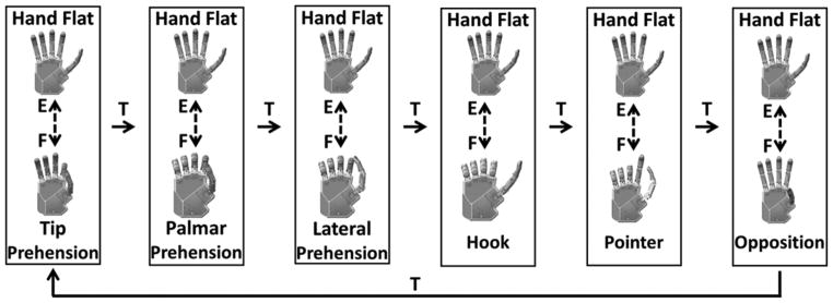
Controller 1 (C1) replicated the finite state machine implemented in a commercially available device: the i-limb prosthetic hand (Touch Bionics; Mansfield, Massachusetts) (Figure 1). This type of finite state machine is typical among available commercial prostheses [19–21]. The architecture consisted of six states corresponding with the six target postures, not including hand flat. A trigger iteratively changed states in a specified order. The trigger allowed for a progression in the sequence of states in a single direction. The trigger command occurred when both flexion and extension EMG signals supersede a tuned threshold (a brief cocontraction). The experimental apparatus provided an audible beep to indicate that a trigger command was recognized (such as in the i-limb prosthetic hand). Once inside a state, the magnitude of the difference between the flexion and extension EMG signals was proportional to the speed of the hand, and the sign of the difference corresponded with the opening or closing of the hand (a velocity control scheme). The fully closed posture of each state coincided with one of the target postures, while the fully opened posture coincided to hand flat (full extension of all digits). Therefore, the only available postures within a state were a linear combination of the corresponding target posture and hand flat.
Figure 1.
Controller 1. Finite state machine based on i-limb prosthetic hand (Touch Bionics; Mansfield, Massachusetts). E = extension electromyography signal, F = flexion electromyography signal, T = electromyography trigger command.
Controller 2: Vanderbilt University Controller
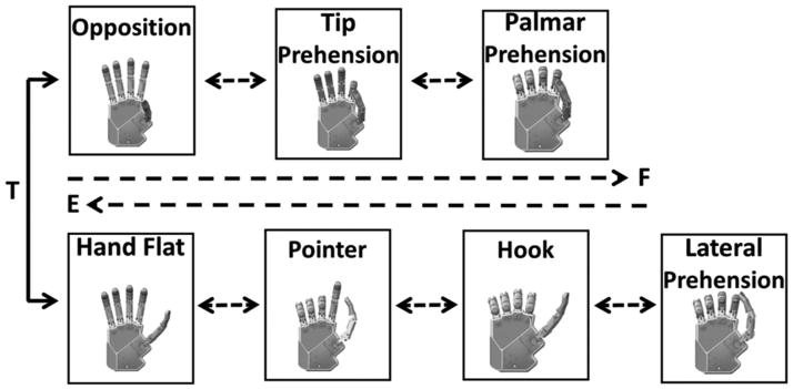
Controller 2 (C2) replicated the Multigrasp Myoelectric Controller developed by Dalley et al. at Vanderbilt University (Figure 2) [12]. The architecture consisted of two states (opposition and reposition) with multiple target postures within each state. The two states were distinguished by the abduction position of the thumb: opposition and reposition. A cocontraction trigger switched between the two states. The trigger command and the hand opening or closing occurred identically to C1. The sequence of postures within each state ensured that the digits closed or opened in a coordinated manner. The transition logic between postures was not reproduced exactly as described in Dalley et al. [12] because of mechanical constraints of the artificial hand used in the present study (see “Experiment A” subsection in the “Methods” section). Specifically, the actuator displacement and force thresholds were not available for use in the transition logic in our study. Instead, the transitions between the states solely depended on the volitional EMG input signals. The hand posture when transitioning between targets was a linear combination of the two nearest target postures.
Figure 2.
Controller 2. Finite state machine based on Multigrasp Myoelectric Controller developed by Dalley et al. [12]. E = extension electromyography signal, F = flexion electromyography signal, T = electromyography trigger command.
Controller 3: Postural Controller
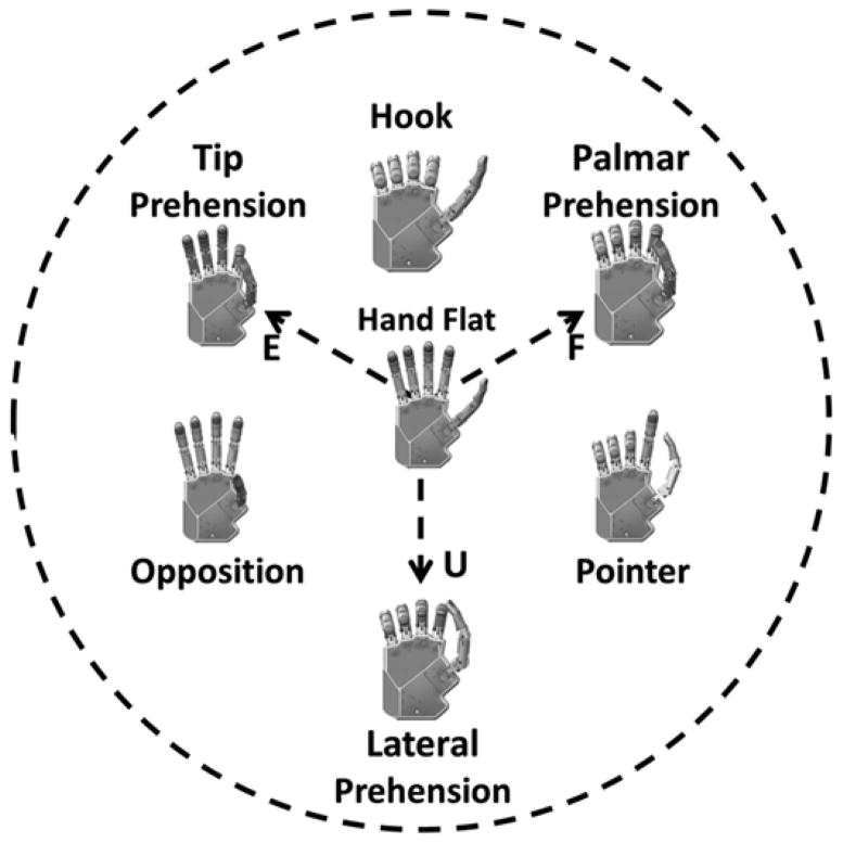
Controller 3 (C3) was a postural controller based on previous work by the authors (Figure 3) [14].* The architecture used EMG signals like a joystick to morph the hand posture. As described previously, the EMG signals were mapped into two control parameters that can be represented by a coordinate in the PC domain. All locations in the PC domain corresponded with a hand posture. In this work, the three EMG signals were mapped in a radial fashion about the origin of the PC domain (Figure 3). The vector summation of the root-mean-square (RMS) EMG values equaled the coordinate position in the PC domain. A position control scheme was used where quiescent EMG signals corresponded with the coordinate at the origin. The coordinate (PCx(t), PCy(t)) was converted into a joint angle array (θ) by a linear transform, the joint angle transform (JAT) (Equation 1):
| (1) |
Figure 3.
Controller 3. Postural controller developed previously by Segil and Weir [14]. Arrangement of target postures in postural control domain is shown as well as radial mapping of electromyography (EMG) signals. E = extension EMG signal, F = flexion EMG signal, U = ulnar deviation EMG signal.
The JAT varied depending on the closest target postures to the coordinate at any given time (i.e., the JAT was spatially dependent). At all times, the hand posture (i.e., the joint angle array) was a linear combination of the two closest target postures where, when the coordinate equaled a target posture position, the MEC reproduced the target posture identically. The architecture did not include discrete states and therefore did not require a trigger signal.
Experimental Methods
Seven nondisabled subjects (age [mean ± standard deviation]: 26 ± 3 yr, all right-handed) completed two experiments (A and B) using the three MECs. Experiment A consisted of the SHAP using a modified IH2 Azzurra artificial hand (Prensilia S.r.l.; Peccioli, Italy) mounted onto a splint [18]. Experiment A tested the ability of the subjects to manipulate physical objects. Experiment B instead consisted of a virtual hand posture matching task (as in Segil and Weir [14]) in order to quantify the ability of the subjects to reproduce all six functional grasps available in each MEC. In a single experimental session (2 h), both experiments were performed using a single controller (either C1, C2, or C3) with experiment A occurring first. Three sessions were scheduled on three different days for each subject. The order of the controllers tested across the three days was randomized across subjects. All subjects claimed to have normal vision and upper-limb function and were not practiced at myoelectric control. All subjects conducted the experiment using their left arms to match the handedness of the robot hand available.
Experiment A
In experiment A, the subjects performed the SHAP wearing the artificial hand. The hand was mounted on a nondisabled splint that included a handlebar so that the physiological limb would maintain an anatomically neutral position. The SHAP is a standardized, time-based hand assessment procedure that measures the hand function relative to normal nondisabled function using 26 ADL tasks that span the functional grasps (Table 2) [18]. It was shown to be reliable and was validated so that results of independent studies can be compared [18]. For example, it was used by Otr et al. to compare prosthetic hands [22] and by Dalley et al. to functionally assess the Multigrasp Myoelectric Controller (i.e., the controller replicated in this work) [12]. As instructed by the SHAP protocol, subjects were asked to complete tasks consisting of the physical manipulation of abstract objects (cylinders, spheres, tabs, etc.) and physical ADLs (turning a door handle [Figure 4], picking up coins, moving containers, lifting a tray, etc.). The 26 tasks were performed as quickly as possible and were self-timed by the subject using a start and stop button as prescribed by the SHAP. Only a subset of grasps (palmar, tip, and lateral prehension) in each MEC was necessary to perform the SHAP (Table 2). The duration of each task was used to calculate a SHAP score (SS), which described the overall function of the subject. The calculation of the SS occurred by inputting the duration of each task in seconds into the proprietary algorithm provided by the SHAP organization through their Web site (http://www.shap.ecs.soton.ac.uk/index.php). Since the SHAP used a time-based protocol, the best performance equated to the fastest average performance across all tasks.
Table 2.
Southampton Hand Assessment Procedure tasks.
| Task (Type and No.) | Name | Grasp |
|---|---|---|
| Abstract Object* | ||
| 1 | Spherical (lightweight) | PP |
| 2 | Tripod (lightweight) | TP |
| 3 | Power (lightweight) | PP |
| 4 | Lateral (lightweight) | LP |
| 5 | Tip (lightweight) | TP |
| 6 | Extension (lightweight) | TP |
| 7 | Spherical (heavyweight) | PP |
| 8 | Tripod (heavyweight) | TP |
| 9 | Power (heavyweight) | PP |
| 10 | Lateral (heavyweight) | LP |
| 11 | Tip (heavyweight) | TP |
| 12 | Extension (heavyweight) | TP |
| Activity of Daily Living | ||
| 13 | Pick up coins | TP |
| 14 | Button board | PP |
| 15 | Food cutting | LP |
| 16 | Page turning | LP |
| 17 | Jar lid | PP |
| 18 | Jug pouring | PP |
| 19 | Carton pouring | PP |
| 20 | Heavy object lift | PP |
| 21 | Light object lift | TP |
| 22 | Tray lift | LP |
| 23 | Rotate key | LP |
| 24 | Open/close zipper | LP |
| 25 | Rotate screw | PP |
| 26 | Door handle | LP |
Light- and heavyweight abstract objects were made of wood and metal, respectively.
LP = lateral prehension, PP = palmar prehension, TP = tip prehension.
Figure 4.
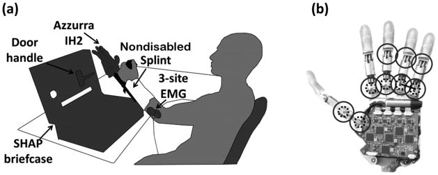
(a) Experimental platform consisted of IH2 Azzurra artificial hand (Prensilia S.r.l.; Peccioli, Italy) mounted onto nondisabled splint, three-site surface electromyography (EMG) acquisition system, Southampton Hand Assessment Procedure (SHAP) briefcase, and door handle task. (b) IH2 Azzurra artificial hand with nine joints (circles) and five motors (dashed circles, ring and little fingers are coupled as shown by solid line).
The artificial hand used during the SHAP was a modified IH2 Azzurra hand. The unmodified version of this hand consists of five underactuated digits (two joints per digit) driven by five motors that actuate the flexion or extension of the thumb and index, middle, and ring and little (as a pair) fingers and the abduction or adduction of the thumb. The hand was modified in order to improve grasp stability during tip and lateral prehension. In particular, the thumb and index fingers were splinted so that they became a single jointed digit about the metacarpophalangeal joint (Figure 4(b)), and compliant material was added to the fingertips.
Before the experiment, the EMG control sites were located by palpating the forearm, and the electrodes were fixed as described previously. Then, the splint with the robot hand was fitted to the subjects’ forearms using adjustable straps in an anatomically correct position. The EMG gains and thresholds were tuned as the subject suspended the hand and splint in order to best compensate for the nominal EMG activity due to the weight of the system.
During the experiment, subjects sat in an upright position in front of a table where the SHAP materials were placed. The subject rehearsed each SHAP task until he or she was able to reliably perform it as suggested by the SHAP assessor’s manual [23]. The subject performed the task until satisfied that he or she had achieved the fastest possible time. Five tasks of the original SHAP were not included in our study (button board, food cutting, rotate key, zipper, and screwdriver tasks) due to the mechanical limitations of the hand available and were given the maximum time (100 s) as prescribed by the SHAP assessor’s manual. Subjects were instructed to rest between SHAP tasks as needed.
Experiment B
In experiment B, the subjects performed a virtual hand posture matching task by controlling the movements of a virtual hand displayed on the laptop using the same EMG control sites as in experiment A. The virtual hand posture matching task was meant to quantify the ability of the subjects to reproduce all six functional grasps available in each MEC (as opposed to the subset of grasps used during the SHAP). The virtual hand had the same physical architecture of the IH2 Azzurra artificial hand and responded in real-time to the output of the MECs. During the experiment, subjects sat in an upright position in front of the laptop (the splint and the robot hand were not used). The subjects were asked to match the posture of the virtual hand to one out of six target postures as quickly as possible. The target posture was displayed as a static image of the virtual hand in the appropriate position [14]. A successful trial consisted of matching the virtual hand to the target posture in 10 s or less (including a 1 s hold time), otherwise the trial was considered a failure. The virtual hand matched the target posture when the coordinate was within the 14 percent radii of the target position in the PC domain and was indicated by the visual interface [24]. The experiment consisted of 60 trials (10 attempts at each target posture). The sequence of target postures was randomized across subjects. Before experiment B, the EMG acquisition was retuned. The virtual hand task tested the ability of each subject to produce the specified target postures, as opposed to the SHAP, which required the completion of the task and not a specific posture.
Performance Metrics
In experiment A, the SS was used as one of the performance metrics [23]. The SS was designed to measure a subject’s artificial hand function and was derived from the time to complete the SHAP tasks, where 100 = non-disabled hand function and 0 = minimal function [23]. The SS was calculated as an across-subject average (unpaired) and was reported in order to compare the prosthetic system with previous studies using the SHAP.
In this work, we introduced the SHAP percent difference (SD), which was the percent difference from the subject average SS as described by Equation 2, where n = the total number of subjects and c = the MEC:
| (2) |
Positive SD occurred when the SS for the MEC was greater than the subject’s average and vice versa. The SD was the preferred performance metric compared with the SS since it was a within-subject comparison and therefore was a more sensitive measure of the relative utility of the MECs.
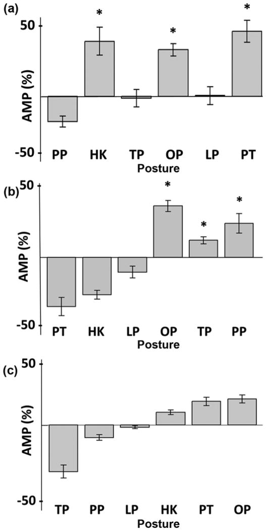
In experiment B, several metrics were used to quantify the performance. The completion rate (CR) is the number of successful trials per total number of trials. The movement time (MT) is the duration of successful trials in seconds, not including the 1 s hold time. The average EMG amplitude (AMP) is a measure of effort based on the RMS of the EMG activity from each electrode (i) for each posture (p). AMP is a within-subject measure and is calculated as the percent difference from the subject RMS AMP for each controller (c) (Equation 3) [25]:
| (3) |
Positive AMP occurs when the subject produces more EMG activity (i.e., effort) for a controller or posture than the subject average and vice versa. The standardization of the EMG tuning methods, as described previously, ensured that the AMP metric accurately reflected the effort of the subject. AMP was only calculated for experiment B since the manipulation tasks in experiment A caused compensatory EMG activity, which was not of interest.
Better performance in experiment A was quantified by higher SS and SD; better performance in experiment B was quantified by higher CR, lower MT, and lower AMP. One-factor analyses of variance were used throughout and Bonferroni post hoc corrections for multiple comparisons were used when applicable, with a significance level of 0.05. Experimental results report mean ± standard error of the mean.
RESULTS
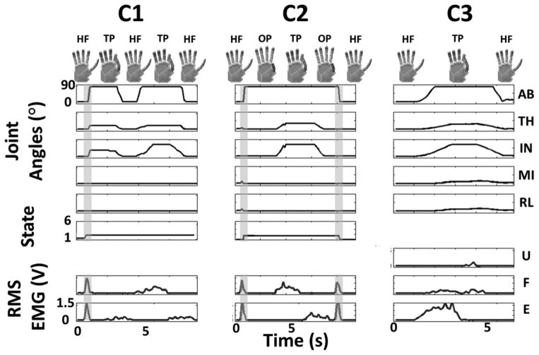
The transformation of EMG signals to joint angle commands for the artificial (or virtual) hand for each MEC was compared (Figure 5). The representative plots in Figure 5 depict the differing logic performed by the three MECs while producing the same outputs. The control sequence for C1 shows a trigger command (vertical gray bar) into the tip prehension state followed by extension, flexion, and extension EMG activity to cause hand flat, tip prehension, and hand flat, respectively. The example for C2 shows a trigger command from the hand flat state into the opposition state followed by a flexion and extension EMG activity to move between opposition, tip pre-hension, and opposition. A second trigger command changed states from opposition back to hand flat. The example for C3 shows predominately extension EMG activity that drives the hand posture from hand flat to tip prehension followed by quiescent EMG activity that relaxes the hand posture back to hand flat.
Figure 5.
Transformation of root-mean-square (RMS) electromyography (EMG) signals into five joint angles. Smoothed EMG signal in red from extensor digitorum (E), flexor digitorum (F), and extensor carpi ulnaris (U) showed muscle activity after filtering and tuning. Joint angle traces from top to bottom for thumb abduction (AB), thumb flexion (TH), index flexion (IN), middle flexion (MI), and ring/little flexion (RL) corresponded with hand posture shown, including hand flat (HF), tip prehension (TP), and opposition (OP). State and posture of controller 1 (C1) and controller 2 (C2) is depicted, and cocontraction trigger signal is highlighted by vertical gray bar. Note that controller 3 (C3) does not require trigger signal since postural control architecture controls hand posture in continuous domain without discrete states.
Experiment A
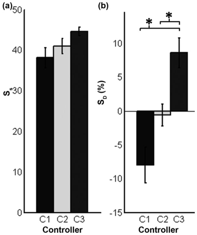
The SS for each controller was equal to 38.0 ± 2.5, 41.0 ± 1.9, and 45.0 ± 1.0 for C1, C2, and C3, respectively (Figure 6(a)). The SS was not significantly different across MECs (p = 0.08). However, the within-subject average SS ranged from 35 to 48 and was found to be significantly different (p < 0.05, not shown). In other words, some subjects were more proficient at the SHAP than others, independent of the controller. Therefore, the SD was the preferred performance metric used since it normalized the SS to the subject average. The mean SD across subjects was equal to −8.0 ± 2.6, −0.6 ± 1.6, and 8.6 ± 2.2 percent for C1, C2, and C3, respectively (Figure 6(b)). Post hoc analysis found that the SD for C3 was significantly greater than for both C1 and C2 (p < 0.001 and p < 0.05, respectively), thereby proving that, on average, subjects performed the ADLs more proficiently using C3 than C1 or C2.
Figure 6.
Experiment A results for each controller with standard error bars (n = 7). (a) Southamptom Hand Assessment Procedure score (SS) describes artificial hand function, where 100 = non-disabled hand function. (b) Southamptom Hand Assessment Procedure percent different (SD) is percent difference of SS of each controller compared with subject mean. *p < 0.05. C1 = controller 1, C2 = controller 2, C3 = controller 3.
Experiment B
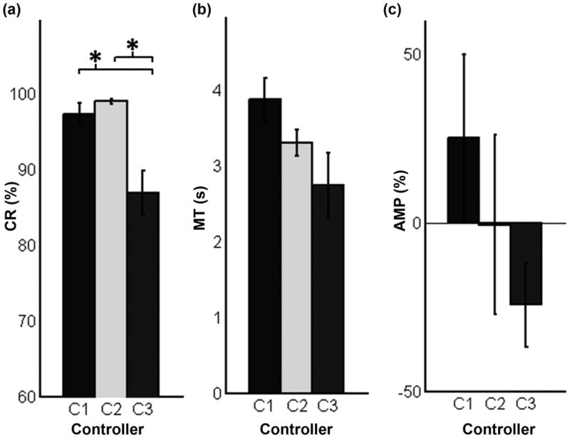
The CRs equaled to 97.0 ± 1.4, 99.0 ± 0.3, and 86.0 ± 2.9 percent for C1, C2, and C3, respectively (Figure 7(a)). Post hoc analysis found that the CR for C3 was significantly less than for both C1 and C2 (p < 0.01 and p < 0.001, respectively). The MTs equaled 3.9 ± 0.3, 3.3 ± 0.2, and 2.7 ± 0.4 s for C1, C2, and C3, respectively (Figure 7(b)). There was no significant difference between the three controllers (p = 0.06); however, there was a strong trend where the MT decreased from C1 to C2 to C3. The AMP equaled 25 ± 24, −1 ± 26, and −24 ± 13 percent for C1, C2, and C3, respectively (Figure 7(c)). There was no significant difference between the three controllers (p = 0.31); however, there was a trend where the AMP decreased from C1 to C2 to C3. To summarize, C3 was the least accurate controller in reproducing the six target postures; however, it tended to be the fastest and least effortful controller.
Figure 7.
Experiment B results averaged for each controller with standard error bars (n = 7). (a) Completion rate (CR) refers to percentage of successful attempts during virtual hand posture matching task. (b) Movement time (MT) describes time to completion during virtual hand matching task. (c) Average electromyography (EMG) amplitude (AMP) is measure of effort based on root-mean-square average of EMG activity and is calculated as percent difference from subject average. Positive AMP describes more than average EMG activity. *p < 0.05. C1 = controller 1, C2 = controller 2, C3 = controller 3.
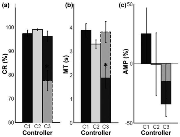
The same results were sorted by target posture in order to analyze the intricacies of the PC architecture used in C3 (Figure 8). In C3, the target postures that required the activation of a single EMG site (palmar, tip, and lateral prehension) are considered 1-degree of freedom (DOF) targets. The 2-DOF target postures (hook, pointer, and opposition) required the activation of two EMG control sites (i.e., a cocontraction). All target postures in C1 and C2 are considered 1-DOF since none require cocontraction. The CR for the 1-DOF trials equaled 97.0 ± 1.4, 99.0 ± 0.3, and 96.0 ± 2.2 percent for C1, C2, and C3, respectively. There was no difference in CR between the controllers for the 1-DOF trials (p = 0.40). However, the CR for C3 2-DOF trials equaled 78.0 ± 4.2 percent and was significantly different (p < 0.001) than the 1-DOF trials. In other words, the failed attempts when using C3 occurred almost exclusively when the target posture required a cocontraction (a 2-DOF target). The MT for the 1-DOF trials equaled 3.9 ± 0.3, 3.3 ± 0.2, and 1.9 ± 0.4 s for C1, C2, and C3, respectively, and the MT for the 2-DOF C3 trials equaled 3.8 ± 0.4 s. The MT for the C3 1-DOF trials was significantly less than the MT for the C1, C2, and C3 2-DOF trials (p < 0.001). The AMP for the 1-DOF trials equaled 25 ± 24, −1 ± 26, and −34 ± 11 percent for C1, C2, and C3, respectively, and the AMP for the C3 2-DOF trials equaled −15 ± 15 percent. There was no significant difference between AMP for the 1-DOF or 2-DOF trials (p = 0.24); however, there was a strong trend where the AMP decreased from C1 to C2 to C3 2-DOF trials to C3 1-DOF trials. In general, the C3 1-DOF trials were equally accurate, faster, and tended to be less effortful than C1 and C2. On the contrary, the C3 2-DOF trials were less accurate, equally timely, and were equally effortful than C1 and C2.
Figure 8.
Experiment B results sorted by target type and controller with standard error bars (n = 7). Solid outlines indicate 1-degree of freedom (DOF) targets; dashed outlines indicate 2-DOF targets. 2-DOF targets require activation of two electromyography signals (cocontraction). *p < 0.05. AMP = average electromyogra-phy amplitude, C1 = controller 1, C2 = controller 2, C3 = controller 3, CR = completion rate, MT = movement time.
Further sorting was performed in order to provide insight into the AMP required to produce the different target postures within each MEC (Equation 3, Figure 9). It is worth recalling that a zero AMP occurred when the posture required the average EMG activity for the subject. For C1, the AMP monotonically increases from the initial target posture (tip prehension) to the most distant one (opposition). This finding is logical since a trigger command is required to sequentially move between states and thereby increases the required effort to reach the more distant target postures. For C2, the AMP is significantly greater (p < 0.001) for target postures in the opposition state (opposition, tip prehension, and palmar prehension) than for the reposition state (pointer, hook, and lateral prehension). Since the hand posture in experiment B was initialized to the hand flat state for all trials and MECs, the opposition state in C2 required an extra trigger command (more EMG activity) to switch from the reposition state. For C3, the AMP is significantly greater (p < 0.001) for the 2-DOF target postures (hook, opposition, and pointer) than for the 1-DOF target postures (palmar, tip, and lateral prehension). This is a logical finding since modulation of two control sites (a cocontraction) is a more effortful task. While the controllers were equally effortful on average, the effort for each target posture differed significantly within each control architecture.
Figure 9.
Average electromyography (EMG) amplitude (AMP) sorted by posture and controller with standard error bars (n = 7). (a) Controller 1, (b) controller 2, and (c) controller 3, where positive AMP refers to postures that require more EMG activity than subject average and vice versa. Postures are arranged along x-axis based on sequence of postures within each controller. *p < 0.05. HK = hook, LP = lateral prehension, OP = opposition, PP = palmar prehension, PT = pointer, TP = tip prehension.
DISCUSSION
Significantly different results from both the physical and virtual assessment procedures were found. An asset of the present study was that it allowed for comparisons between MECs due to the standardized experimental design where the same interface and hardware were used for all conditions.
In experiment A, C3 proved to be the best performing architecture as described by SD (Figure 6). The trigger command used in C1 and C2, but not in C3, inherently retarded the completion of the ADL. Subjects were observed producing the trigger command during the reaching phase of the ADL in order to complete the task as quickly as possible when using C1 and C2. The absence of a trigger command in C3 proved to be advantageous. This finding supported a similar study in which pattern recognition (without trigger commands) and state machine MECs were compared [26]. Furthermore, the architectures of C1 and C2 required extension activity in order to release an object, whereas C3 required quiescent activity. These traits resulted from the velocity control scheme in C1 and C2 compared with the position control scheme in C3. A velocity control scheme deciphered EMG activity as a speed and direction of hand movement and therefore quiescent EMG activity equated to no hand movement. EMG activity was necessary to close and open the hand. A position control scheme deciphered EMG activity as a position within the architecture. In C3, EMG activity was only necessary to close the hand; the hand opened when quiescent EMG activity was detected. However, the velocity control scheme used in C1 and C2 allowed the user to relax while grasping an object as opposed to in C3, which required continual EMG activity in order to maintain a grasp. This fact could cause fatigue (although not noticed here) and might need to be mitigated with switches or other logic within C3. In general, the need for extension activity in order to release an object in C1 and C2 seemed to slow the completion of the tasks compared with C3.
In experiment B, C3 was the least accurate (lowest CR) controller (Figure 7). We found that the dimensionality of the architectures affected the accurate reproduction of target postures. More specifically, the state machine architectures used in C1 and C2 restricted the subject to a linear arrangement of states, and therefore, the posture-matching task only required the modulation of one EMG signal at a time. This linear arrangement in C1 and C2 provided a more accurate interface. The PC architecture used in C3 presented the same postures in a planar, two-dimensional arrangement. Thereby, half of the target postures required the modulation of one EMG signal (1-DOF) and half required the modulation of two EMG signals (2-DOF) in order to reproduce the target posture. The added dimension of the PC architecture in C3 (i.e., the need for cocontractions) negatively affected the CR of the MEC (Figure 8(a)). These results supported our previous findings that described a reduction in CR with an increase in dimensionality [14]. We believe that the dimensionality of the MEC is a major determining factor in the ability of a subject to control a prosthetic hand.
The MT metric in experiment B described the same trend seen in the SS in experiment A (Figure 7). The MT tended to decrease from C1 to C2 to C3, which mirrored the SS and SD metrics. Furthermore, the MT for the C3 1-DOF trials proved to be significantly faster than the other controllers (Figure 8(b)). The similar trend between the SS and the MT metric was logical since both are time-based metrics. This trend supported the fact that both the physical and virtual assessment protocols limited confounding variables and therefore produced similar results across assessment techniques.
The AMP metric described the relative effort required for each controller and posture. While the controllers required equal effort on average (Figure 7(c)), the effort for each target posture within each MEC differed significantly and depended on the controller architecture. In general, the sequential arrangement of states in C1 caused the closer postures to the initial position to be achieved more easily. Similarly in C2, the postures within the initial state (hand flat state) were achieved more easily than the postures not in the initial state (opposition state). In C3, the AMP metric highlighted the difficulty of commanding the 2-DOF target postures compared with the 1-DOF target postures. Note that the AMP metric was biased by controller architecture. The initial posture and state within each controller was the same for all trials in experiment B to ensure a standardized methodology across controllers. The reordering of states within C1 and/or the rearrangement of postures in the PC domain in C3 would have caused the AMP values to differ for the specific postures. However, we concluded that the general insights still hold for all of the controllers; the effort increased with the number of trigger commands required in C1 and C2, and the 2-DOF postures in C3 required more effort than the 1-DOF postures.
The clinical implementation of the three controllers is feasible today. The EMG acquisition and processing was performed using clinically available hardware and standard processing techniques. Several five-motor prosthetic hands are available today [1], and six-motor devices are becoming available [19]. A clinical consideration when implementing the finite state machine architectures (C1 and C2) is the design of the trigger signal. This work implemented the same trigger design as Dalley et al. [12] for both C1 and C2; however, more complex trigger designs, including hold open, double impulse, and/or triple impulse, are clinically available [19]. In general, the trigger design must balance the ease of use for the subject with the reliability of the trigger signal. Subject overexertion and/or false triggers should be minimized in order to maintain a high-quality control interface when using finite state machine architectures. A clinical consideration when implementing the PC architecture (C3) is the availability of three independent surface EMG sites on the residual limb of persons with transradial amputation. Three control sites are preferable to two in order to span the entire PC domain using a radial mapping of EMG signals in the PC domain. Our previous work discussed two, three-, and four-site EMG control interfaces using different maps in the PC domain [14]. Anecdotally, we have found that three independent sites can be found on the residual limbs of subjects with both congenital limb loss and trauma-induced limb deficiency [27]. However, the two-site system used for both C1 and C2 is advantageous since it reduces the cost of the prosthesis system compared with the three-site system required for C3.
The limitations of this work include the use of a left-handed prosthesis, the lack of training time, the lack of subjects with transradial amputation, and the disregard for pattern recognition MECs. The experiments were performed using the left limb of the subjects due to the handedness of the physical prosthesis even though all seven subjects were right-handed. We believe that the ability of subjects to use these MECs would change with additional training time but that these results are robust to additional training and still describe the clear differences in MEC architectures. In the future, we plan to further test the PC architecture implemented in C3 within a population of persons with amputation. We did not test a pattern recognition-based MEC in this work since we are not aware of an algorithm that can classify seven hand postures reliably during a clinically focused test like the SHAP. A surprising development from this work was the advantage to using a position control scheme as opposed to a velocity control scheme in the PC architecture. We described the opposite preference when used in a virtual center-out target acquisition task.*
CONCLUSIONS
We conclude that the optimal parameters for PC architectures depend on whether the MEC is being used in a virtual environment or with a physical device; velocity control schemes are beneficial for virtual tasks while position control schemes are beneficial for physical tasks, including object manipulation and other ADLs. Here, we show using virtual and physical assessment techniques with standardized protocols that the PC architectures rival the state-of-the-art finite state machine architectures for clinically viable MECs.
Acknowledgments
Funding/Support: This material was based on work supported by the Department of Veterans Affairs Office of Research and Development Rehabilitation Research and Development Service (grant I01BX007080), the Whitaker Foundation, the Italian Ministry of Education University, the FIRB-2010 MY-HAND Project (grant RBFR10VCLD), and the European Commission under the WAY project (grant FP7-ICT-228844).
Abbreviations
- ADL
activity of daily living
- AMP
average electromyography amplitude
- C1
controller 1
- C2
controller 2
- C3
controller 3
- CR
completion rate
- DOF
degree of freedom
- EMG
electromyography
- JAT
joint angle transform
- MEC
myoelectric controller
- MT
movement time
- PC
postural control
- RMS
root-mean-square
- SHAP
Southampton Hand Assessment Procedure
- SD
Southampton Hand Assessment Procedure percent difference
- SS
Southampton Hand Assessment Procedure score
Footnotes
Segil J, Weir R. A novel postural control algorithm for control of multi-functional myoelectric prosthetic hands. J Rehabil Res Dev. In review.
Segil J, Weir R. A novel postural control algorithm for control of multi-functional myoelectric prosthetic hands. J Rehabil Res Dev. In review.
Author Contributions:
Study concept and design: J. L. Segil, M. Controzzi, R. F. Weir, C. Cipriani.
Acquisition of data: J. L. Segil, M. Controzzi.
Analysis and interpretation of data: J. L. Segil.
Drafting of manuscript: J. L. Segil, C. Cipriani.
Critical revision of manuscript for important intellectual content: M. Controzzi, R. F. Weir.
Financial Disclosures: Drs. Cipriani and Controzzi hold Prensilia S.r.l., the company that manufactures the artificial hand used in this study, under license to Scuola Superiore Sant’Anna.
Institutional Review: Informed consent according to the Declaration of Helsinki was obtained before conducting the experiments.
Participant Follow-Up: The authors have no plans to notify the study subjects of the publication of this article.
References
- 1.Belter JT, Segil JL, Dollar AM, Weir RF. Mechanical design and performance specifications of anthropomorphic prosthetic hands: A review. J Rehabil Res Dev. 2013;50(5):599–618. doi: 10.1682/jrrd.2011.10.0188. http://dx.doi.org/10.1682/JRRD.2011.10.0188. [DOI] [PubMed] [Google Scholar]
- 2.Keller AD, Taylor C, Zahn V. Studies to determine the functional requirements for hand and arm prosthesis. Los Angeles (CA): Department of Engineering, University of California; 1947. [Google Scholar]
- 3.Parker P, Englehart K, Hudgins B. Myoelectric signal processing for control of powered limb prostheses. J Electromyogr Kinesiol. 2006;16(6):541–48. doi: 10.1016/j.jelekin.2006.08.006. http://dx.doi.org/10.1016/j.jelekin.2006.08.006. [DOI] [PubMed] [Google Scholar]
- 4.Biddiss EA, Chau TT. Upper limb prosthesis use and abandonment: A survey of the last 25 years. Prosthet Orthot Int. 2007;31(3):236–57. doi: 10.1080/03093640600994581. http://dx.doi.org/10.1080/03093640600994581. [DOI] [PubMed] [Google Scholar]
- 5.Childress DS, Weir RF. Control of limb prostheses. Atlas Limb Prosth. 2004;2:175–98. [Google Scholar]
- 6.Cipriani C, Segil J, Birdwell J, Weir R. Dexterous control of a prosthetic hand using fine-wire intramuscular electrodes in targeted extrinsic muscles. IEEE Trans Neural Syst Rehabil Eng. 2014;22(4):828–36. doi: 10.1109/TNSRE.2014.2301234. http://dx.doi.org/10.1109/TNSRE.2014.2301234. [DOI] [PMC free article] [PubMed] [Google Scholar]
- 7.Hudgins B, Parker P, Scott RN. A new strategy for multi-function myoelectric control. IEEE Trans Biomed Eng. 1993;40(1):82–94. doi: 10.1109/10.204774. http://dx.doi.org/10.1109/10.204774. [DOI] [PubMed] [Google Scholar]
- 8.Englehart K, Hudgins B. A robust, real-time control scheme for multifunction myoelectric control. IEEE Trans Biomed Eng. 2003;50(7):848–54. doi: 10.1109/TBME.2003.813539. http://dx.doi.org/10.1109/TBME.2003.813539. [DOI] [PubMed] [Google Scholar]
- 9.Li G, Schultz AE, Kuiken TA. Quantifying pattern recognition-based myoelectric control of multifunctional transradial prostheses. IEEE Trans Neural Syst Rehabil Eng. 2010;18(2):185–92. doi: 10.1109/TNSRE.2009.2039619. http://dx.doi.org/10.1109/TNSRE.2009.2039619. [DOI] [PMC free article] [PubMed] [Google Scholar]
- 10.Kyberd PJ, Chappell PH. The Southampton Hand: An intelligent myoelectric prosthesis. J Rehabil Res Dev. 1994;31(4):326–34. [PubMed] [Google Scholar]
- 11.Cipriani C, Zaccone F, Micera S, Carrozza MC. On the shared control of an EMG-controlled prosthetic hand: Analysis of user prosthesis interaction. IEEE Trans Robot. 2008;24(1):170–84. http://dx.doi.org/10.1109/TRO.2007.910708. [Google Scholar]
- 12.Dalley SA, Varol HA, Goldfarb M. A method for the control of multigrasp myoelectric prosthetic hands. IEEE Trans Neural Syst Rehabil Eng. 2012;20(1):58–67. doi: 10.1109/TNSRE.2011.2175488. http://dx.doi.org/10.1109/TNSRE.2011.2175488. [DOI] [PMC free article] [PubMed] [Google Scholar]
- 13.Matrone GC, Cipriani C, Carrozza MC, Magenes G. Real-time myoelectric control of a multi-fingered hand prosthesis using principal components analysis. J Neuroeng Rehabil. 2012;9(1):40. doi: 10.1186/1743-0003-9-40. http://dx.doi.org/10.1186/1743-0003-9-40. [DOI] [PMC free article] [PubMed] [Google Scholar]
- 14.Segil JL, Weir RF. Design and validation of a morphing myoelectric hand posture controller based on principal component analysis of human grasping. IEEE Trans Neural Syst Rehabil Eng. 2014;22(2):249–57. doi: 10.1109/TNSRE.2013.2260172. http://dx.doi.org/10.1109/TNSRE.2013.2260172. [DOI] [PMC free article] [PubMed] [Google Scholar]
- 15.Pistohl T, Cipriani C, Jackson A, Nazarpour K. Abstract and proportional myoelectric control for multi-fingered hand prostheses. Ann Biomed Eng. 2013;41(12):2687–98. doi: 10.1007/s10439-013-0876-5. http://dx.doi.org/10.1007/s10439-013-0876-5. [DOI] [PMC free article] [PubMed] [Google Scholar]
- 16.Scheme E, Englehart K. Electromyogram pattern recognition for control of powered upper-limb prostheses: State of the art and challenges for clinical use. J Rehabil Res Dev. 2011;48(6):643–59. doi: 10.1682/jrrd.2010.09.0177. http://dx.doi.org/10.1682/JRRD.2010.09.0177. [DOI] [PubMed] [Google Scholar]
- 17.Young AJ, Smith LH, Rouse EJ, Hargrove LJ. Classification of simultaneous movements using surface EMG pattern recognition. IEEE Trans Biomed Eng. 2013;60(5):1250–58. doi: 10.1109/TBME.2012.2232293. http://dx.doi.org/10.1109/TBME.2012.2232293. [DOI] [PMC free article] [PubMed] [Google Scholar]
- 18.Light CM, Chappell PH, Kyberd PJ. Establishing a standardized clinical assessment tool of pathologic and prosthetic hand function: Normative data, reliability, and validity. Arch Phys Med Rehabil. 2002;83(6):776–83. doi: 10.1053/apmr.2002.32737. http://dx.doi.org/10.1053/apmr.2002.32737. [DOI] [PubMed] [Google Scholar]
- 19.i-limb ultra revolution clinician manual [Internet] Mansfield (MA): Touch Bionics; 2014. Sep, Available from: http://www.touchbionics.com/sites/default/files/files/i-limb%20ultra%20revolution%20clinician%20manual%20September%202014.pdf. [Google Scholar]
- 20.Bebionic v2 product brochure [Internet] Leeds (United Kingdom): RSL Steeper; 2011. Jul 2, Available from: http://rslsteeper.com/uploads/files/159/bebionic-ukrow-product-brochure-rsllit294-issue-21.pdf. [Google Scholar]
- 21.Michelangelo hand user manual [Internet] Duderstadt (Germany): Otto Bock HealthCare GmbH; 2012. Available from: http://www.living-with-michelangelo.com/fileadmin/downloads/anwender/english/user_product_brochure.pdf. [Google Scholar]
- 22.Otr OV, Reinders-Messelink HA, Bongers RM, Bouwsema H, Van Der Sluis CK. The i-LIMB hand and the DMC plus hand compared: A case report. Prosthet Orthot Int. 2010;34(2):216–20. doi: 10.3109/03093641003767207. http://dx.doi.org/10.3109/03093641003767207. [DOI] [PubMed] [Google Scholar]
- 23.Assessor’s SHAP Protocol [Internet] Southampton (United Kingdom): University of Southampton; 2012. Available from: http://www.shap.ecs.soton.ac.uk/files/protocol.pdf. [Google Scholar]
- 24.Radhakrishnan SM, Baker SN, Jackson A. Learning a novel myoelectric-controlled interface task. J Neurophysiol. 2008;100(4):2397–2408. doi: 10.1152/jn.90614.2008. http://dx.doi.org/10.1152/jn.90614.2008. [DOI] [PMC free article] [PubMed] [Google Scholar]
- 25.Masuda K, Masuda T, Sadoyama T, Inaki M, Katsuta S. Changes in surface EMG parameters during static and dynamic fatiguing contractions. J Electromyogr Kinesiol. 1999;9(1):39–46. doi: 10.1016/s1050-6411(98)00021-2. http://dx.doi.org/10.1016/S1050-6411(98)00021-2. [DOI] [PubMed] [Google Scholar]
- 26.Wurth SM, Hargrove LJ. Real-time comparison of conventional direct control and pattern recognition myoelectric control in a two-dimensional Fitts’ law style test. Proceedings of the 2013 35th Annual International Conference of the IEEE Engineering in Medicine and Biology Society; 2013 Jul 3–7; Osaka, Japan. pp. 3630–33. [DOI] [PubMed] [Google Scholar]
- 27.Ajiboye AB, Weir RF. A heuristic fuzzy logic approach to EMG pattern recognition for multifunctional prosthesis control. IEEE Trans Neural Syst Rehabil Eng. 2005;13(3):280–91. doi: 10.1109/TNSRE.2005.847357. http://dx.doi.org/10.1109/TNSRE.2005.847357. [DOI] [PubMed] [Google Scholar]


