Abstract
This paper investigated the power losses of unsegmented and segmented energy coupling coils for wireless energy transfer. Four 30-cm energy coupling coils with different winding separations, conductor cross-sectional areas, and number of turns were developed. The four coils were tested in both unsegmented and segmented configurations. The winding conduction and intrawinding dielectric losses of the coils were evaluated individually based on a well-established lumped circuit model. We found that the intrawinding dielectric loss can be as much as seven times higher than the winding conduction loss at 6.78 MHz when the unsegmented coil is tightly wound. The dielectric loss of an unsegmented coil can be reduced by increasing the winding separation or reducing the number of turns, but the power transfer capability is reduced because of the reduced magnetomotive force. Coil segmentation using resonant capacitors has recently been proposed to significantly reduce the operating voltage of a coil to a safe level in wireless energy transfer for medical implants. Here, we found that it can naturally eliminate the dielectric loss. The coil segmentation method and the power loss analysis used in this paper could be applied to the transmitting, receiving, and resonant coils in two- and four-coil energy transfer systems.
Index Terms: Coil segmentation, dielectric power loss, displacement current, implantable medical devices, low-voltage operation, wireless intermediate-range scheme for energy and signal transmission (WISEST)
I. Introduction
Wireless energy transmission by magnetic coupling eliminates the need for wires connecting the load from the power source. Implantable medical devices are among the many applications that could take advantage of wireless energy transmission to improve the quality of life of patients. Since the implanted device can be powered without the requirement of percutaneous plugs, wires, or conduits piercing the patient’s skin, the risk of infection can be significantly reduced [1], [2].
In traditional transcutaneous energy coupling systems, such as implantable middle ear hearing devices, the separation between the transmitting and receiving coils is usually <1 cm, and the coil diameter is a few cm [3], [4]. Since the size of the transmitting coil is small, the coupling coefficient is very sensitive to the coil alignment and coupling failure may happen easily [1], [5], [6]. A larger transmitting coil size can produce a more evenly distributed magnetic field over a larger volume around the center of the coil. Recent work suggests that a 30-cm diameter transmitting coil wrapped around the body can power up deep-seated implantable battery-less ultrasonic pulser-receiver, in a manner where the received energy is relatively insensitive to the receiving coil position [7]. Others have demonstrated that a Helmholtz-coil configured transmitting coil with a large diameter can generate a homogeneous magnetic field in the human body. Puers et al. [8] and Xin et al. [9] demonstrated that 30-cm diameter Helmholtz-coils can transmit sufficient energy to operate capsule endoscopes, which are locomotive in the gastrointestinal tract. However, the required coil voltage is proportional to the inductance, which is proportional to the coil size, the number of turns, and the coil’s operating frequency. Therefore, a high operating voltage is often required for midrange wireless energy transfer since a high frequency (megahertz range) is usually used to improve the energy transfer capability. The required coil voltage ranges from a few hundred volts to several kilovolts. For example, transmitting coil voltages as high as 3.5 kV [8] were needed to transmit the few hundred mW power needed to operate a capsule endoscope. If the implanted device requires more power, higher transmitting coil voltages, more turns, and higher currents would be needed, which may pose a safety risk. A high operating voltage also increases the intrawinding displacement current, and thus the dielectric power loss.
Several approaches for improving the energy efficiency of the energy coupling coils have been developed. In one implementation, a system with a dc-to-load efficiency above 77% was achieved by using copper pipe coils to reduce winding conduction loss due to the skin effect and by minimizing the volume of the solid in the coil former to reduce the dielectric loss [10]. In addition, a large winding separation was introduced to reduce the proximity effect, reducing the winding conduction loss at high frequency. In another implementation, the power transfer efficiency of a pair of capacitively loaded inductors was analyzed [11]. In that study, the coupling coil had two turns and was printed on a single-sided PCB, so the intrawinding capacitance and dielectric loss were negligible. However, in some practical applications, the energy coupling coils had to be tightly wound on a solid former or printed on a multilayer PCB, and the effects of the parasitic intrawinding capacitor and dielectric loss became significant at high frequencies. These parasitic effects could be represented by intrawinding capacitors and resistors connected in parallel to the winding inductance across each turn to improve the coil model accuracy [12]–[14].
It would be desirable to reduce the conduction and dielectric losses of the energy coupling coil while maintaining tight and compact windings. Lee and Lorenz [15] proposed a new coil layout to significantly reduce the power loss caused by the skin and proximity effects. We recently proposed a coil segmentation technique to reduce the coil voltage to improve safety for transmitting energy to deep and locomotive implantable devices [16]. In the segmented coil configuration, each turn of the coil is divided into segments by series capacitors. At the resonant frequency, the voltage across each coil segment is canceled by the series capacitor voltage. Therefore, the voltage between two windings becomes very small at the resonant frequency, and the series LRC impedance is much lower than the intrawinding impedance. Since negligible amount of displacement current flows through the parasitic intrawinding components, the dielectric loss is naturally eliminated by using this coil segmentation technique.
In this paper, we utilized a well-established lumped circuit model [12], [13], with and without the consideration of the intrawinding resistors and capacitors, to investigate the power loss of segmented and unsegmented energy coupling coils. The winding conduction loss and intrawinding dielectric loss were investigated individually. The coil parameters were measured and used to verify the models for the segmented and unsegmented coils. Four coils with different winding separations, conductor cross-sectional areas, and number of turns were investigated and compared. This analysis and the coil segmentation technique could be applied to the transmitting and receiving coils in a two-coil wireless energy coupling system, and also in the resonant coils in a four-coil system using strongly coupled magnetic resonances [11], [17], [18].
II. Coil Structure of the Energy Coupling Coils
A. Unsegmented Coils
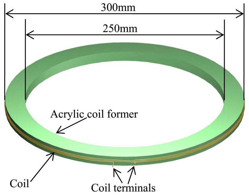
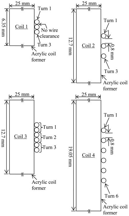
To investigate wire and dielectric losses, we constructed four energy coupling coils (Coils 1–4), each with different numbers of turns, cross-sectional areas, and winding separations. All of the coils were wound around acrylic coil formers with an outer diameter of 30 cm. A representative 3-D coil drawing is shown in Fig. 1. The cross-sectional views of the four coils are shown in Fig. 2. The coil parameters are tabulated in Table I. The coils were made of 20 AWG (0.8-mm diameter) enameled copper wires. Coils 1–3 had three turns and Coil 4 had six. Coils 1 and 3 were tightly wound. A winding clearance of 0.8 mm was added to Coils 2 and 4 to investigate the reduction of dielectric and winding conduction losses. Coil 3 was made of two wires connected in parallel while the others used single strand wires. Using two parallel wires allowed us to investigate the effect of increasing the cross-sectional area on the conduction loss.
Fig. 1.
Structure of the unsegmented energy coupling coil.
Fig. 2.
Cross-sectional view of the energy coupling coil.
TABLE I.
Parameters of the ENERGY Coupling Coils
| Coil 1 | Coil 2 | Coil 3 | Coil 4 | |
|---|---|---|---|---|
| Wire clearance | No | 0.8 mm | No | 0.8 mm |
| Number of turns | 3 turns | 3 turns | 3 turns | 6 turns |
| Number of wires per turn | 1 | 1 | 2 | 1 |
| Acrylic former Thickness | 6.35 mm | 12.7 mm | 12.7 mm | 19.05 mm |
| Inductance, Lsi | 2.97 μH | 2.73 μH | 2.64 μH | 4.73 μH |
| Intra-winding capacitance, Cpi | 86.7 pF | 17.3 pF | 96.2 pF | 41.8 pF |
B. Segmented Coils
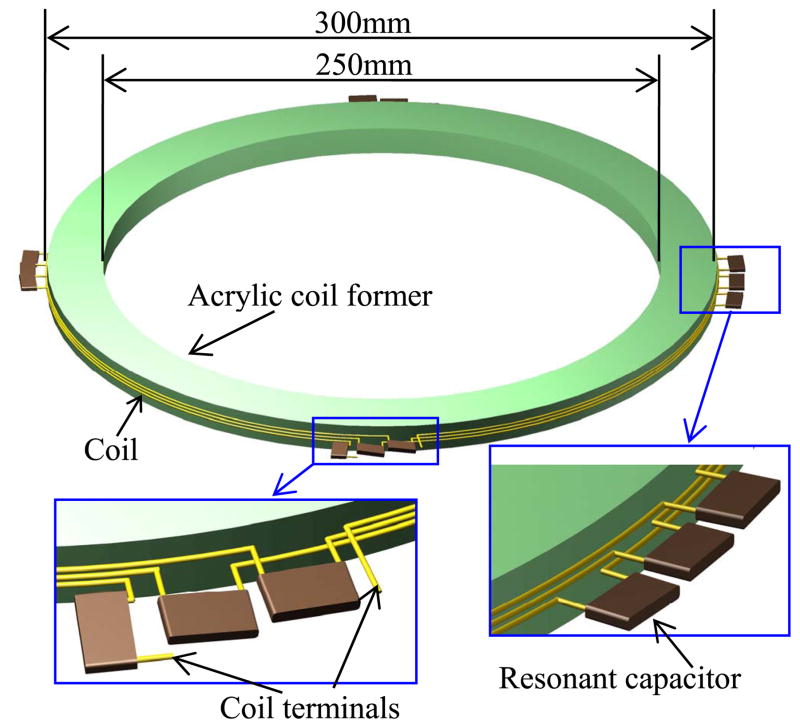
The segmented coils were constructed by dividing each turn of the unsegmented coils described in Section A into four segments. The electrical characteristics of the segmented and unsegmented coils will be analyzed and compared in the following sections. In the segmented coils, low equivalent-series-resistance (ESR) capacitors were inserted between two coil segments and the capacitors were evenly distributed around the coils as shown in Fig. 3. Each three-turn coil (Coils 1–3) had 12 segments; the six-turn coil (Coil 4) had 24. The resonant frequency of the segmented coils was tuned to the 6.78-MHz (±15 kHz) industrial, scientific, and medical (ISM) band by selecting the appropriate capacitance values, which is given by
Fig. 3.
Structure of the segmented energy coupling coil with resonant capacitors.
| (1) |
where fr is the resonant frequency (6.78 MHz), Ls is the inductance of the whole coil, and n is the number of turns.
III. Circuit Model
A. Unsegmented Coils
A well-established equivalent circuit model [12], [13] for an n-turn energy coupling coil was used to analyze the coil characteristics (Fig. 4). The n-turn coil was divided into n portions in the circuit model. It should be noted that the inductance for turn i (Lsi) includes both the self-inductance of the individual turn and the mutual inductance caused by the magnetic coupling from other turns. In the following analysis, the Lsi values were assumed to be equal; they were obtained by simply dividing the measured inductance of the whole coil, Ls, by n. Similarly, the winding resistance values for turn i (Rsi) was obtained by dividing the measured resistance of the whole coil, Rs, by n. The parasitic intrawinding capacitance values (Cpi) were included in the model to illustrate the displacement current paths between windings at high frequencies. This displacement current flowing through the dielectric materials, such as the coil former and wire coating, causes dielectric loss. The dielectric loss can be represented by a resistor in series or in parallel to the intrawinding capacitor. In the circuit model, the dielectric loss was represented by parallel resistance values Rpi. This loss can be significant when the coil voltage is high [14]. Assuming that the parasitic components of the coil are evenly distributed, the coil impedance is given by (2), as shown at the bottom of the page.
Fig. 4.
Equivalent circuit model for the n-turn unsegmented energy coupling coil.
| (2) |
B. Segmented Coils
The circuit model used for the segmented coils is shown in Fig. 5. It was similar to that for an unsegmented coil except an equivalent capacitor was placed in series to each turn. This capacitance, Csi, represents the lumped value of the four series capacitors placed around a turn. The series resistance for each turn, Rsi, includes both the ESR of the series capacitors and the winding resistance of a turn. The impedance of the segmented coil is given by (3), as shown at the bottom of the page.
Fig. 5.
Equivalent circuit model for the n-turn segmented energy coupling coil with resonant capacitors.
| (3) |
C. Parameter Acquisition
The circuit parameters were obtained by measuring the coils with an impedance analyzer (HP 4194A). We found that the values of the winding inductance and intrawinding capacitance mainly depended on the coil geometry and were not very sensitive to the frequency since the coils did not consist of a nonlinear ferrite material. The measured inductance and capacitance of the coils at 1 MHz are shown in Table I.
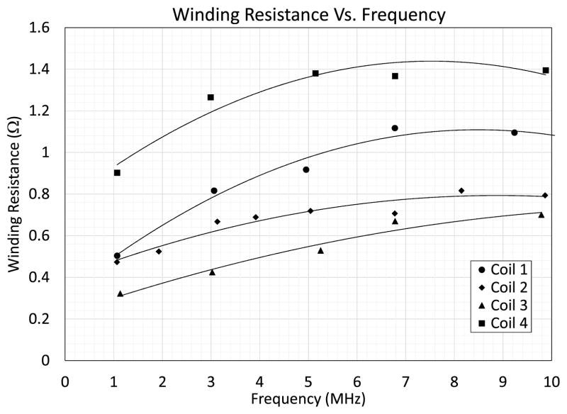
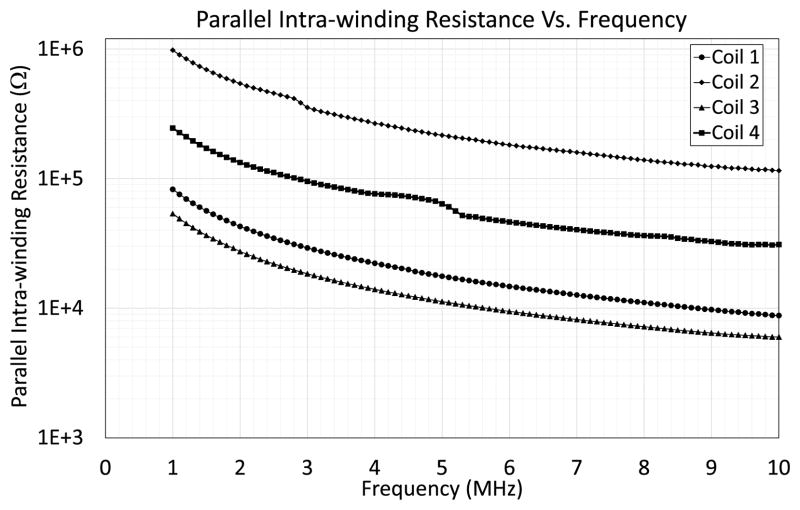
The series winding resistance and the parallel intrawinding resistance, however, were frequency dependent as shown in Figs. 6 and 7, respectively. It is important to note that the winding resistance directly obtained by the impedance analyzer in the series-inductance and resistance (Ls, Rs) mode does not represent the actual winding resistance correctly in the megahertz frequency range since the parallel intrawinding capacitors and resistors (dielectric loss) significantly influenced the measurement. In order to tangibly reduce the effects of these intrawinding parasitic components, we inserted resonant capacitors in series to the coil as described in Section II-B. The series capacitors and the coil segments form a series RLC resonant circuit in each segment. At the series resonant frequency, the impedance of this series RLC circuit is minimum and equal to the resistance of the series capacitor and the coil wire. The value of this series resistance per turn, Rsi, is very small (usually in the order of milli-ohm), and is much smaller than the impedance of the parallel intrawinding components. Thus, with the series resonant capacitors inserted around the coil, the influence of the intrawinding parasitic components on the winding resistance measurement can be eliminated. The winding resistance was obtained by subtracting the ESR of the capacitors from the measured total resistance of the series RLC circuit. Plots of the winding resistance of the whole coil, Rs, shown in Fig. 6 were obtained by using several sets of series capacitors that generated resonant frequencies ranging from 1 to 10 MHz.
Fig. 6.
Measured winding resistance of the energy coupling coils versus frequency.
Fig. 7.
Measured parallel intrawinding resistance, Rpi, of the energy coupling coils versus frequency.
D. Circuit Model Verification
1) Unsegmented Coils
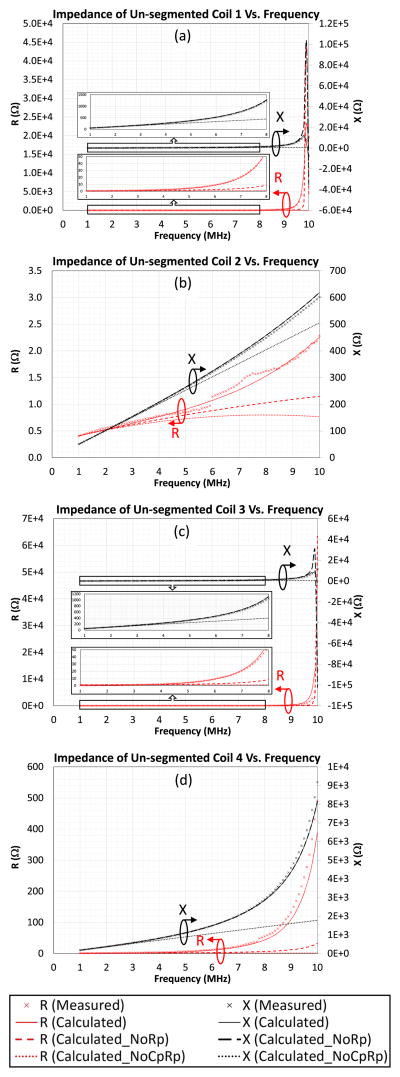
We have practically verified the circuit models set forth in Sections A and B by substituting the measured circuit parameters of the four coils into (2) and (3), and comparing the calculated impedance values with the measured results. The measured and calculated real and imaginary components of the impedance of the unsegmented coils (R and X, respectively) are shown in Fig. 8. The measured impedance is represented by the × signs. The calculated impedance with both of the intrawinding capacitors and resistors included in the model, without the intrawinding resistors, and without both of the intrawinding capacitors and resistors are represented by the solid, dashed, and dotted lines, respectively.
Fig. 8.
Measured and calculated impedance of unsegmented coils.
When the intrawinding resistors, Rpi, were not included in the circuit model, the real part of the impedance (dashed lines in Fig. 8), which represents the power loss, is lower than the measured value at off-resonant frequencies, and the peak values of the calculated real and imaginary parts at the resonant frequency are much higher than that of the measured results. This result demonstrates that the power loss of the coil is underestimated if Rpi is not included. Comparing the real part of the impedance with and without Rpi, the dielectric loss is noticeable at a few megahertz and becomes more significant at frequencies close to the self-resonant frequencies of the coils. When both of Cpi and Rpi were not included in the calculation (dotted lines in Fig. 8), both of the real and imaginary parts were significantly underestimated.
To better model the energy coupling coils, both of the intrawinding components, Cpi and Rpi, should be included. When both of Cpi and Rpi were included in the calculation model, the measured and calculated impedance (real and imaginary parts) shown in Fig. 8 were consistent. The difference between the measured and calculated real and imaginary parts is <8.71% and 3.43%, respectively, at the frequency of interest (6.78 MHz). In Fig. 8(b) and (d), the real component of the impedance had larger measurement errors since its magnitude was much smaller than the imaginary component. However, both of the calculated real and imaginary components of the coil impedance are consistent with the measured curves, and the impedance of the coil could be predicted at the operating frequency of 6.78 MHz when both of Rpi and Cpi were considered in the calculation. The verified circuit model with the measured parameters, including the intrawinding capacitors and resistors, was adopted to predict the individual power losses caused by the intrawinding resistors and the winding resistors as to be described in Section IV.
2) Segmented Coils
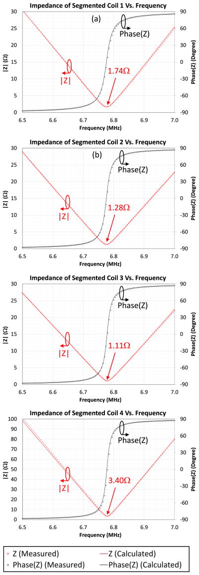
The segmented coils were obtained by dividing the coils used in Section III-D.1 into four equal segments per turn using series capacitors. Thus, the coil inductance, winding resistance, and winding conduction loss listed in Tables I–III are the same for both the segmented and unsegmented coils. The resonant frequency of the segmented coils was adjusted to the ISM band of 6.78 MHz ± 15 kHz. There were 12 series capacitors used in Coils 1–3, and 24 capacitors in Coil 4. The required capacitance values were predicted based on (1), and the actual capacitance values are listed in Table II. In order to locate the resonant frequency and fine tune the coils, the magnitude and phase of the coil impedance versus frequency were measured and are plotted in Fig. 9. The measured impedance was compared with the calculated results based on the coil model and (3). Since at the resonant frequency, the impedance of the series RLC circuit in each segment was much smaller than that of the intrawinding components, the effects of the intrawinding components were negligible and the calculated impedance of the coils without Rpi and Cpi for comparison were not included in Fig. 9. The impedance at the resonant frequency, i.e., the minimum impedance, represents the total series resistance of the series capacitors and the windings. The coil winding resistance was obtained by subtracting the ESR of the capacitors from the total series resistance. The measured and calculated segmented coil resistance (including the ESR of the series capacitor), the measured ESR of the series capacitors and the winding resistance are listed in Table II. Since the calculated results shown in Figs. 8 and 9 and Table II using the circuit model in Figs. 4 and 5 agree well with the impedance measurements, we used the circuit model to predict power losses of the coils in the following section.
TABLE III.
Predicted Voltage, and Power Losses of the Coils Based on the Circuit Model at 6.78 MHz
| Coil 1 | Coil 2 | Coil 3 | Coil 4 | ||
|---|---|---|---|---|---|
| Inductor current | 1 A | 1 A | 1 A | 0.5 A | |
| Winding loss of both the segmented and un-segmented coils, Pwinding | From measured Rs | 1.14 W | 0.71 W | 0.67 W | 0.34 W |
| From the model | 1.03 W | 0.65 W | 0.61 W | 0.37 W | |
| Voltage per turn of the un-segmented coils, Vi | 126.46 V | 114.16 V | 112.53 V | 100.77 V | |
| Pdielectric of the un-segmented coils | 3.68 W | 0.24 W | 4.52 W | 1.47 W | |
| Total power loss of un-segmented Coils, Ptotal | From measured Rs | 4.82 W | 0.95 W | 5.19 W | 1.81 W |
| From the model | 4.71 W | 0.89 W | 5.13 W | 1.84 W | |
TABLE II.
Parameters of the Coils and the Series Capacitors at 6.78 MHz
| Coil 1 | Coil 2 | Coil 3 | Coil 4 | ||
|---|---|---|---|---|---|
| Series capacitance for the segmented coils, Csi | 755 pF | 785.6 pF | 842 pF | 473.3 pF | |
| Resistance of the segmented coil (including the winding resistance and ESR of the series capacitors) | Measured | 1.74 Ω | 1.28 Ω | 1.11 Ω | 3.40 Ω |
| Calculated | 1.63 Ω | 1.22 Ω | 1.05 Ω | 3.51 Ω | |
| Total ESR of the series capacitors | 0.60 Ω | 0.57 Ω | 0.44 Ω | 2.03 Ω | |
| Winding resistance of both the segmented and un-segmented coils, n × Rsi | Measured | 1.14 Ω | 0.71 Ω | 0.67 Ω | 1.37 Ω |
| Calculated | 1.03 Ω | 0.65 Ω | 0.61 Ω | 1.48 Ω | |
| Real part of the un-segmented coil | Measured | 16.89 Ω | 1.32 Ω | 17.07 Ω | 19.91 Ω |
| Calculated | 16.53 Ω | 1.23 Ω | 17.57 Ω | 18.19 Ω | |
| Measured intra-winding resistance of both the segmented and un-segmented coils, Rpi | 13.0 k Ω | 163.3 k Ω | 8.4 k Ω | 41.4 k Ω | |
Fig. 9.
Measured and calculated impedance of segmented coils.
IV. Power Loss Analysis
The power losses of the energy coupling coils at the frequency of interest (6.78 MHz) mainly came from the winding conduction loss and dielectric loss, which were represented by the winding and intrawinding resistance values Rsi and Rpi, respectively. Since the coil dimensions (30 cm) were much smaller than the wavelength (44.3 m), the radiation loss was negligible. We investigated the power losses caused by the winding resistance and the intrawinding dielectric individually. To compare the power losses among the four coils developed for this paper, the magnetomotive force (MMF) generated by the coils were set to 3-A turns, i.e., the inductor current was 1 A for Coils 1–3 and 0.5 A for Coil 4.
A. Winding Conduction Loss
The conduction loss of the winding can be obtained when the winding resistance and the inductor current are known. In the previous section, we obtained the winding resistance without the influence of the intrawinding component using resonance and a coil segmentation technique. The conduction loss of the winding was obtained by Pwinding = I2Rs, where I was the current flowing through the inductor branch in the circuit model shown in Figs. 4 and 5, and Rs was the total winding resistance (n × Rsi). The winding conduction losses obtained from the measured Rs and the circuit model were consistent as listed in Table III, and the tolerance was less than about 10%. Among the three-turn coils (Coils 1–3), Coil 1 had the highest winding resistance. Coils 1 and 2 had the same conductor cross-sectional area, but Coil 1 was tightly wound and Coil 2 had a 0.8-mm clearance between the two windings. The winding resistance and conduction loss of Coil 1 were about 60% higher than that of Coil 2 due to the proximity effect. Similarly, although Coil 3 had two times the conductor cross-sectional area of Coil 2, it was tightly wound and the proximity effect was more pronounced. Thus, its conduction power loss was not half but only a few percent less than that of Coil 2. Despite the proximity effect, in the group of the three-turn coils, Coil 3 had the lowest winding resistance and conduction loss since its winding had the largest cross-sectional area.
We also investigated the effect of number of turns on the power loss by comparing Coils 2 and 4, which had the same winding separation and conductor cross-sectional area. Since Coil 4 had twice the number of turns, its resistance was approximately two times as that of Coil 2. To compare the power loss of the coils, we set the inductor current of Coil 4 to 0.5 A to produce the same MMF as the 3-turn coils. Although Coil 4 had a higher resistance, it required half the current to produce the same MMF, resulting in a factor of two reduction in the conduction power loss, as shown in Table III.
Accordingly, the conduction power loss could be reduced effectively by introducing winding clearance, increasing the conduction cross-sectional area, and the number of turns. However, increasing the conductor cross-sectional area while reducing the winding clearance did not effectively reduce the conduction loss.
B. Intrawinding Dielectric Loss
Dielectric loss occurs when there is a potential difference between two windings. It increases with increasing frequency since the displacement current flowing from one winding to another through the dielectric material, including the wire coating and the former, is more significant at high frequency (i.e., in the megahertz range). In the segmented coils, since the voltage across each coil segment was canceled by the adjacent series capacitor at the resonant frequency, the potential difference between two windings, and thus the dielectric loss, was negligible. In the unsegmented coils, since the winding voltage was proportional to the operating frequency, the potential difference between two windings increased as frequency increases. Therefore, the displacement current and thus the dielectric loss became significantly higher at high operating frequencies, especially when a larger coil for longer range wireless energy transfer was used.
The winding voltages per turn of the four coils were calculated based on the equation V = 2π f Lsi I and are shown in Table III when they were not segmented. In the calculation, the winding resistance was ignored since it was much smaller than the impedance caused by the series inductance. As the coil inductance and operating frequency were relatively high, we can see that the coil voltages per turn, which represents the potential different between two adjacent windings, were higher than a hundred volts even when the inductor current was only 1 A. The dielectric losses of the coils were calculated based on the equation , where Rpi is the measured intrawinding resistance between two adjacent turns, as shown in Fig. 7 and Table II. In contrast to the winding conduction loss, Coil 3 had the highest dielectric loss since it did not have added winding clearance and it had the largest surface area, which increased the admittance and thus the displacement current between windings. Coils 2 and 4, which had a clearance of 0.8 mm between windings, had lower dielectric losses than the other two coils without winding clearance. The dielectric loss of Coil 4 was higher than that of Coil 2 since it had more turns and thus more paths for the displacement current between windings.
C. Total Power Loss
Since the dielectric loss in a segmented coil was negligible, any losses that occurred were primarily from the winding conduction loss shown in Table III. These results suggest that the power loss of a segmented coil can be reduced by increasing the number of turns, or the conductor thickness, or by reducing the proximity effect with a larger winding clearance. In contrast, the total power loss of an unsegmented coil, Ptotal, contains winding conduction loss as well as the dielectric loss as listed in Table III.
While the dielectric loss of Coil 2 was about one-third of its conduction loss, the dielectric losses of the other coils were higher than their respective conduction losses. The dielectric losses of Coils 1, 3, and 4 were higher than the conduction losses by about 3, 7, and 4 times, respectively. Alternatively, we can also see the high dielectric losses occurred in the unsegmented coils by comparing the large values of the real part of the unsegmented coil impedance, which represents the total power losses, with the segmented coil winding resistance as shown in Table II. By comparing Coils 2 and 4, we can see that the dielectric loss was smaller in a coil with less turns. This finding suggests that the effect of dielectric loss can be reduced by reducing the number of turns. However, it would also increase the winding conduction loss as indicated in Table III, and thus the power transfer capability. Accordingly, the dielectric loss of an unsegmented coil represents a very large portion of its power loss if the windings are tightly wound.
V. Power Efficiency Measurement
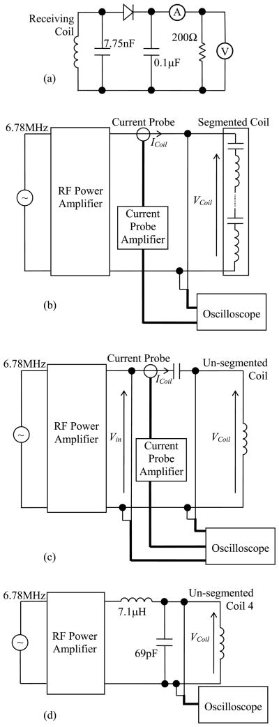
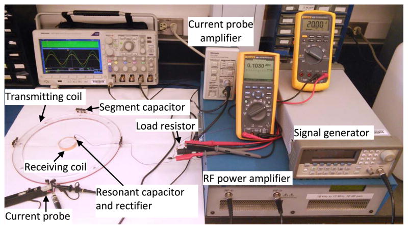
Measurements with a wireless energy coupling system were obtained to evaluate whether the power loss reduction found for the segmented coil translated to improved power efficiency as well. In the evaluation, we set the coil of interest, i.e., a 30-cm segmented or unsegmented coil, to be the energy transmitting coil. Apart from the transmitting coil, the power efficiency of an energy coupling system also depends on the parameters of the receiving coil, such as the wire thickness, coil location, and the loading condition. A 5-cm diameter receiving coil positioned at the center of the transmitting coil was used as a reference for the power efficiency comparison. The receiving coil had 1 turn and was made of copper tape with a thickness of 0.04 mm and a width of 11.2 mm wrapped around a 5-cm diameter acrylic disk. The measured inductance of the receiving coil was 72 nH. A parallel capacitor with a capacitance of 7.75 nF was used to tune the coil to 6.78 MHz. The receiving circuit was loaded with a 200-Ω resistor through a half-wave rectifier as shown in Fig. 10(a). Fig. 11 shows the setup for measuring the power efficiency of the energy coupling system.
Fig. 10.
Circuit diagrams for the measurements of (a) output load power delivered from the receiving circuit, the input power with (b) segmented and (c) unsegmented transmitting coils, and (d) voltage of Coil 4.
Fig. 11.
Experimental setup for wireless energy transfer using segmented Coil 1 as the transmitting coil.
The power efficiency is defined as the ratio of the output load power to the input power to the transmitting coil with the series capacitors. We measured the output power at the rectifier output instead of the power delivered from the receiving coil because the extended wires between the receiving coil and the resonant capacitor for the coil current measurement significantly increased the power loss and detuned the resonant circuit, even though the wires were as short as 2 cm. The input power to the transmitting coil circuit was obtained by averaging the product of the instantaneous input voltage, vin(t), and current, iCoil(t), in one cycle as described in [19]. Fig. 10(b) and (c) shows the block diagrams of the setups for measuring the input power of the segmented and unsegmented coils, respectively. In the case of measuring the unsegmented coil, since the operating frequency was high and the coils were highly inductive (i.e., the phase difference between the coil voltage and current was close to 90 degrees) the alternating instantaneous vin(t) · iCoil(t) product was very high compared with the average value. Thus, the measured input power to the unsegmented coils using the above-mentioned method was very sensitive to the time delay error of the current probe. To solve this problem, we connected a low-loss series capacitor to the transmitting coil so that the phase between the input voltage and current was close to zero. After this addition, the values of the instantaneous v(t) · i(t) product were mostly positive, and the power measurement error due to the current probe time delay was significantly reduced. The required values of the series capacitance for the unsegmented coils were predicted by using a Smith Chart instead of using the resonant frequency formula for an LC circuit (f = 1/√LC) because of the undesired influence of the intrawinding capacitance. The setup shown in Fig. 10(c) could not be used to measure the coil voltage of unsegmented Coil 4 since the resultant parallel capacitance attributed to the intrawinding capacitance and the voltage probe capacitance were too large to tune the circuit to zero phase at 6.78 MHz. The voltage of unsegmented Coil 4 was measured separately using an LC matching circuit as shown in Fig. 10(d).
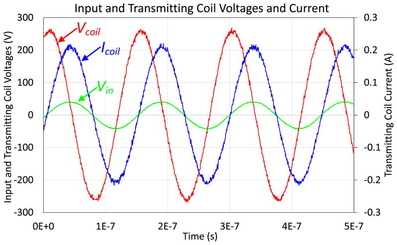
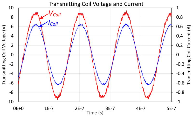
In the power efficiency comparison test, the load power was set to 2 W by adjusting the input current to the transmitting coil. The measured transmitting coil voltage VCoil, current ICoil, input power, and load power of the wireless coupling system using the four segmented and unsegmented coils are listed in Table IV. The input voltage Vin, coil voltage VCoil, and current ICoil waveforms of the unsegmented transmitting Coil 1 are shown in Fig. 12. The segmented Coil 1 voltage VCoil and current ICoil waveforms are shown in Fig. 13. Since the load power was set to the same level for all measurements, the required MMFs (input current × number of turns) of all the segmented coils were the same, as shown in Table IV. However, the input currents of the unsegmented transmitting coils were lower since there were circulating displacement currents flowing between the winding conductors and the intrawinding capacitors and resistors, which are different among the coils. As explained in the power loss analysis, the displacement current in the unsegmented coil resulted in dielectric loss, thus the power efficiency of the unsegmented coil was significantly lower than its segmented counterpart. From Table IV, the power efficiencies of unsegmented Coils 1 and 3 were markedly lower than that of Coil 2 since the two coils were tightly wound and the dielectric loss was significant. The measured power efficiency of the system using unsegmented Coil 4 was relatively low since the capacitance of the input series capacitor used for this coil was much smaller than that for the other coils as shown in Table IV. The ESR of a capacitor with smaller capacitance is usually higher in the same type of capacitor. Thus, the power efficiency of the system using unsegmented Coil 4 is lower than that using Coil 2. This result indicates that, at high operating frequencies, using an unsegmented coil with more turns along with a series matching capacitor is less practical since the required capacitance can be practically too small, and its ESR results in higher power loss.
TABLE IV.
Voltage, Current, Input and Output Power, Efficiency, and Required Series Capacitance of the Energy Coupling System Using the Segmented and Unsegmented Coils as the Transmitting Coil
| Un-segmented Coils | Segmented Coils | |||||||
|---|---|---|---|---|---|---|---|---|
| Coil 1 | Coil 2 | Coil 3 | Coil 4 | Coil 1 | Coil 2 | Coil 3 | Coil 4 | |
| Voltage across the transmitting coils | 183 V | 170 V | 164 V | 298 V | 6.39 V | 6.46 V | 6.27 V | 12.38 V |
| Input current | 0.15 A | 0.31 A | 0.16 A | 0.05 A | 0.45 A | 0.45 A | 0.45 A | 0.22 A |
| Input power | 4.29 W | 3.57 W | 4.03 W | 4.12 W | 2.86 W | 2.79 W | 2.78 W | 2.73 W |
| Load power | 2.00 W | 2.00 W | 2.00 W | 2.07 W | 2.00 W | 2.00 W | 2.00 W | 2.02 W |
| Efficiency | 46.6% | 56.0% | 49.6% | 50.2% | 69.9% | 71.7% | 71.9% | 74.0% |
| Required series/segment capacitance | 20 pF | 45 pF | 25 pF | 4.2 pF | 755 pF | 785.6 pF | 842 pF | 473.3 pF |
Fig. 12.
Input voltage Vin, transmitting coil voltage VCoil, and current ICoil of the unsegmented Coil 1 when the load was 2 W.
Fig. 13.
Segmented Coil 1 voltage VCoil, and current ICoil when the load was 2 W.
VI. Discussion
In this paper, we analyzed the power losses of segmented and unsegmented energy coupling coils. The winding conduction and intrawinding dielectric losses of four coils with different winding separations, conductor cross-sectional areas, and numbers of turns were investigated individually. The segmented energy coupling coil was originally proposed to reduce the operating voltage to improve safety for transmitting energy to implantable medical devices [16]. Here, we found that the segmented coil has another inherent advantage over its unsegmented counterpart: the dielectric loss caused by the coil insulation and the former is negligible at the resonant frequency, and at this frequency, the inductor voltage across each coil segment is canceled by the adjacent series capacitor.
The coils we tested in this paper were wound on solid acrylic formers, which are rigid, so the measurements are repeatable. The wire coating, the glue, and the coil former materials were the sources of the dielectric loss. These can be reduced by reducing the volume of the material close to the winding, but then the coil may become less rigid. In previous feasibility tests of wireless energy transfer by magnetic coupling [10], the coil wire, without enamel insulation, was wound on a plastic former with minimal amount of solid material to minimize the impact of the dielectric. In configurations or applications where the coil requires a rigid former or is printed on a multilayer PCB, the intrawinding dielectric loss should be included [12], [14] when operating in the megahertz operating frequency range.
We found that both the winding conduction loss and intrawinding dielectric loss could be reduced by increasing the winding separation because of the reduced proximity effect and intrawinding admittance. Previous work [10] and [17] used helical coils with a large winding separation to increase the power efficiency of the coupling coils. Such a large winding separation may not be feasible in some situations where space is restricted, e.g., windings printed on multilayer PCB, or tightly packed receiving coils in a medical implanted device. In these situations, the dielectric loss can be noticeable, and the intrawinding resistance must be included in the energy coupling circuit model. A recent study demonstrated that the dielectric loss of a double-layer printed spiral coil for wireless power transfer could be reduced by using low loss tangent (<0.0007) dielectric material [14]. From the results presented in this paper, the dielectric loss can be essentially eliminated by using a segmented coil without using expensive low-loss material, even when the coil is tightly wound. In a situation where the coil needs to be tightly packed, the power loss can further be reduced by using coils with surface spiral layout to reduce skin and proximity effects [15]. In this paper, the coil parameters were obtained by the measurement of the actual coils using an impedance analyzer. Alternatively, a finite-element analysis model can be utilized to predict the electrical parameters of a coil with different dimensions and configuration without fabricating the actual coil.
This paper presents a power loss analysis of general air-core coils with and without segmentation. It can be applied to the energy transmitting or receiving coil in a two-coil energy coupling system, and also to the resonant coils in a four-coil system using strongly coupled magnetic resonances [17]. In addition, the coil segmentation method can be used in the resonant coils to significantly reduce the dielectric loss and the required coil voltage, which can otherwise be extremely high [14].
VII. Conclusion
In this paper, we compared the power losses of unsegmented and segmented energy coupling coils for wireless energy transfer. Both calculated and measured results show that coil segmentation using series capacitors can significantly reduce the power loss of an energy coupling coil. Measured results from the power efficiency evaluation of a wireless energy coupling system also show that the power efficiency of the system using a segmented coil is markedly higher than that using an unsegmented coil.
We utilized a well-established lumped circuit model that took into consideration the intrawinding capacitors and resistors to evaluate the winding conduction loss and intrawinding dielectric loss of four air-core coils with different winding separations, conductor cross-sectional areas, and numbers of turns. The circuit model was practically verified by comparing the measured and calculated impedance of the four coils. The calculated results obtained based on the model were consistent with impedance measurements in both the unsegmented and the segmented coils. As expected, the results showed that the winding conduction loss caused by the proximity effect can be reduced by introducing a clearance between the windings. However, increasing the cross-sectional area of the winding without introducing a winding clearance did not reduce the conduction loss effectively. Adding clearance between windings also reduced the intrawinding dielectric loss that occurs in the coil former and insulation if the coil is unsegmented. We also found that the dielectric loss could be reduced by using a coil with less turns at the cost of increasing the conduction loss and reducing the coil’s energy transfer capabilities.
The recently proposed coil segmentation technique investigated here was originally designed to reduce the high-voltage safety issues for transmitting energy to medical implantable devices. These results show that this technique can also naturally eliminate the dielectric loss even if the coil is tightly wound. The segmentation technique and power loss analysis used in this paper can be applied to the energy transmitting and receiving coils in a two-coil energy coupling system. It would also be appropriate for resonant coils in a four-coil system in order to reduce the operating voltage and the dielectric loss.
Acknowledgments
This work was supported by the U.S. National Institutes of Health under Grant P01CA174645.
Biographies

Sai Chun Tang (S’97–M’01–SM’11) was born in Hong Kong in 1972. He received the B.Eng. degree (Hons.) and the Ph.D. degree in electronic engineering from the City University of Hong Kong, Hong Kong, in 1997 and 2000, respectively.
He was a Research Fellow with the City University of Hong Kong after the graduation. He joined the National University of Ireland, Galway, Ireland, as a Visiting Academic in 2001, and the Laboratory for Electromagnetic and Electronic Systems at the Massachusetts Institute of Technology, Cambridge, MA, USA, in 2002. Since 2004, he has been with the Department of Radiology, Brigham and Women’s Hospital, Harvard Medical School, Boston, MA, USA, for the developments of ultrasound diagnosis devices and noninvasive treatment systems using high-intensity focused ultrasound. In 2008, he became a Faculty in Radiology at Harvard Medical School. His current research interests include electronic medical devices, high-frequency electromagnetism, low-profile power converter design, and analog electronics.

Nathan J. McDannold received the B.S. and Ph.D. degrees in physics from the University of Virginia, Charlottesville, VA, USA, and Tufts University, Boston, MA, USA, in 1995 and 2001, respectively.
He is the Research Director of the Focused Ultrasound Laboratory at the Brigham and Women’s Hospital and an Associate Professor of Radiology at Harvard Medical School, Boston, MA, USA. He is primarily involved in the development and implementation of MRI-based thermometry methods, animal experiments testing, MRI and ultrasound related work, and clinical focused ultrasound treatments of breast tumors, uterine fibroids, and brain tumors. His current research interests include studying the use of ultrasound for temporary disruption of the blood-brain barrier, which may allow for targeted drug delivery in the brain.
Footnotes
Color versions of one or more of the figures in this paper are available online at http://ieeexplore.ieee.org.
References
- 1.Soma M, Galbraith DC, White RL. Radio-frequency coils in implantable devices: Misalignment analysis and design procedure. IEEE Trans Biomed Eng. 1987 Apr;BME-34(4):276–282. doi: 10.1109/tbme.1987.326088. [DOI] [PubMed] [Google Scholar]
- 2.Waters BH, Sample AP, Bonde P, Smith JR. Powering a ventricular assist device (VAD) with the free-range resonant electrical energy delivery (FREE-D) system. Proc IEEE. 2012 Jan;100(1):138–149. [Google Scholar]
- 3.Park IY, Lim HG, Yoon YH, Kim MK, Song BS, Cho JH. A transcutaneous recharging system with the function of bi-directional signal transmission for fully-implantable middle ear hearing devices. IEICE Trans Fundam Electron, Commun Comput Sci. 2006;E89-A(6):1962–1694. [Google Scholar]
- 4.Joung GB, Cho BH. An energy transmission system for an artificial heart using leakage inductance compensation of transcutaneous transformer. IEEE Trans Power Electron. 1998 Nov;13(6):1013–1022. [Google Scholar]
- 5.Catrysse M, Hermans B, Puers R. An inductive power system with integrated bi-directional data-transmission. Sens Actuators A, Phys. 2004 Sep;115(2–3):221–229. [Google Scholar]
- 6.Galbraith DC, Soma M, White RL. A wide-band efficient inductive transdennal power and data link with coupling insensitive gain. IEEE Trans Biomed Eng. 1987 Apr;BME-34(4):265–275. doi: 10.1109/tbme.1987.326076. [DOI] [PubMed] [Google Scholar]
- 7.Tang SC, Jolesz FA, Clement GT. A wireless batteryless deep-seated implantable ultrasonic pulser-receiver powered by magnetic coupling. IEEE Trans Ultrason, Ferroelectr, Freq Control. 2011 Jun;58(6):1211–1221. doi: 10.1109/TUFFC.2011.1931. [DOI] [PubMed] [Google Scholar]
- 8.Puers R, Carta R, Thoné J. Wireless power and data transmission strategies for next-generation capsule endoscopes. J Micromech Microeng. 2011;21(5):054008. [Google Scholar]
- 9.Xin W, Yan G, Wang W. Study of a wireless power transmission system for an active capsule endoscope. Int J Med Robot Comput Assist Surgery. 2010 Mar;6(1):113–122. doi: 10.1002/rcs.298. [DOI] [PubMed] [Google Scholar]
- 10.Pinuela M, Yates DC, Lucyszyn S, Mitcheson PD. Maximizing DC-to-load efficiency for inductive power transfer. IEEE Trans Power Electron. 2013 May;28(5):2437–2447. [Google Scholar]
- 11.Kiani M, Ghovanloo M. The circuit theory behind coupled-mode magnetic resonance-based wireless power transmission. IEEE Trans Circuits Syst I, Reg Papers. 2012 Sep;59(9):2065–2074. doi: 10.1109/TCSI.2011.2180446. [DOI] [PMC free article] [PubMed] [Google Scholar]
- 12.Adjaye RE, Cornick KJ. Distribution of switching surges in the line-end coils of cable-connected motors. IEE J Electr Power. 1979 Feb;2(1):11–21. [Google Scholar]
- 13.Martinez-Tarifa JM, Amaras-Duarte H, Sanz-Feito J. Frequency-domain model for calculation of voltage distribution through random wound coils and its interaction with stray capacitances. IEEE Trans Energy Convers. 2008 Sep;23(3):742–751. [Google Scholar]
- 14.Chen K, Zhao Z. Analysis of the double-layer printed spiral coil for wireless power transfer. IEEE J Emerg Sel Topics Power Electron. 2013 Jun;1(2):114–121. [Google Scholar]
- 15.Lee SH, Lorenz RD. Development and validation of model for 95%-efficiency 220-W wireless power transfer over a 30-cm air gap. IEEE Trans Ind Appl. 2011 Nov-Dec;47(6):2495–2504. [Google Scholar]
- 16.Tang SC. A low-operating-voltage wireless intermediate-range scheme for energy and signal transmission by magnetic coupling for implantable devices. Special Issue on Wireless Power Transfer, IEEE J Emerg Sel Topics Power Electron. to be published. [Google Scholar]
- 17.Kurs A, Karalis A, Moffatt R, Joannopoulos JD, Fisher P, Soljačić M. Wireless power transfer via strongly coupled magnetic resonances. Sci Exp. 2007 Jun;317(5834):83–86. doi: 10.1126/science.1143254. [DOI] [PubMed] [Google Scholar]
- 18.Kumar A, Mirabbasi S, Chiao M. Resonance-based wireless power delivery for implantable devices. Proc. IEEE Conf. Biomed. Circuits Syst. Conf; Nov. 2009; pp. 25–28. [Google Scholar]
- 19.Tang SC, Hui SYR, Chung HSH. A low-profile power converter using printed-circuit board (PCB) power transformer with ferrite polymer composite. IEEE Trans Power Electron. 2001 Jul;16(4):493–498. [Google Scholar]


