The number and complexity of 3D-printed models from DICOM images acquired and interpreted by radiologists is growing exponentially, and radiologists will benefit from a fundamental understanding of the principles and applications of 3D printing.
Abstract
While use of advanced visualization in radiology is instrumental in diagnosis and communication with referring clinicians, there is an unmet need to render Digital Imaging and Communications in Medicine (DICOM) images as three-dimensional (3D) printed models capable of providing both tactile feedback and tangible depth information about anatomic and pathologic states. Three-dimensional printed models, already entrenched in the nonmedical sciences, are rapidly being embraced in medicine as well as in the lay community. Incorporating 3D printing from images generated and interpreted by radiologists presents particular challenges, including training, materials and equipment, and guidelines. The overall costs of a 3D printing laboratory must be balanced by the clinical benefits. It is expected that the number of 3D-printed models generated from DICOM images for planning interventions and fabricating implants will grow exponentially. Radiologists should at a minimum be familiar with 3D printing as it relates to their field, including types of 3D printing technologies and materials used to create 3D-printed anatomic models, published applications of models to date, and clinical benefits in radiology.
Online supplemental material is available for this article.
©RSNA, 2015
See also the article by Matsumoto et al.
SA-CME LEARNING OBJECTIVES
After completing this journal-based SA-CME activity, participants will be able to:
■ Describe the imaging, postprocessing, and equipment requirements to make a 3D-printed model from standard radiologic images.
■ Identify the advantages and disadvantages of the various technologies and materials available for 3D-printed models.
■ Discuss the existing literature and evidence base on the use of 3D-printed models in medicine and describe future applications of 3D medical printing.
Introduction
The radiology “three-dimensional (3D) laboratory” emerged from academic radiologists who developed and implemented software tools to reformat diagnostic images, most commonly from computed tomography (CT), in anatomic as opposed to traditional planes (1,2). Volume rendering portrayed on a two-dimensional (2D) monitor has enabled 3D visualization of anatomy and pathologic conditions, which has broadly affected radiology and provided an important method for radiologists to communicate pertinent findings to medical care teams. Early work in the field typically required a separate, dedicated workstation that processed Digital Imaging and Communications in Medicine (DICOM) images transferred from a CT scanner capable of generating isotropic or near-isotropic thin-section images. Although early 3D visualization was not reimbursed, the field advanced to satisfy an increasing clinical demand. Today, thin-client software (shared software stored on a central server) integrated into an institution’s picture archiving and communication system (PACS) can be launched as needed, and reformatted images are permanently archived as an indispensable component of the patient’s medical record.
A “3D printing laboratory” in radiology is now likely to emerge, with some parallels to and differences from early 3D laboratories. Although overall 3D printing costs continue to decrease, start-up expenses without near-term reimbursement will likely limit early adoption to radiologists currently proficient in advanced visualization. However, creating accurate 3D-printed models requires an additional fund of knowledge and mastery of new technical skills to generate unique printable file formats recognized by 3D printers. Early-adopter radiologists must invest in developing and honing these skills. Over time, these skills will be incorporated into training programs and implemented with use of software that is better integrated to radiology workflow, facilitating the pathway for most or all radiologists to use a 3D printer as a step to improved patient care.
The field of 3D printing emerged in the nonmedical sciences primarily to fill the need for rapid engineering of design prototypes. Thus, the first challenge addressed in this review is to learn the entrenched engineering nomenclature, including the types of 3D printers and materials available. We prioritize technologies used for printing from medical images as reported in the biomedical imaging literature, including those used to design customized 3D-printed implants. Radiologists who can grasp the underlying concepts will be poised to become integral members of future teams that will shape the field.
The physical space and financial investment required for early radiology-based 3D printing laboratories will be greater than those for early 3D visualization laboratories. Another important challenge is the time investment required of already-busy radiologists to maintain an innovative leadership role in a dynamic field. However, according to Wohlers Report 2013 (3), there has been a notable increase in the growth rate of 3D printing market revenue. While the compounded annual growth rate of all 3D printing–related products and services was 25% during the 25-year period before 2010, growth between 2010 and 2012 alone was 27%. Despite the overall growth of 3D printing, it is likely that reimbursement for 3D-printed models will follow the establishment and acceptance of evidence-based guidelines. The authors have printed over 8000 medical 3D models between 2003 and the present at the 3D Medical Applications Center in the Department of Radiology at Walter Reed National Military Medical Center. At least 7500 of these models have been from CT DICOM images. The authors have also served as principle investigators over the last 3 years for National Institutes of Health grants and Department of Defense contracts that substantially use 3D printing to meet the specific aims. On the basis of this collective experience, we comprehensively review current data arranged by organ system as a framework for radiologists to master the technology and contribute to scholarship in the field. The literature to date is largely formed by case reports; while complex studies continue to emerge, more work with a focus on clinical benefits is needed to form guidelines and support reimbursement.
A handheld printed model derived from DICOM images represents a natural progression from 3D visualization, and demand for interventional planning is poised to increase as the technology becomes more available. Radiologists who embrace and master this technology early in its implementation will help define appropriate clinical indications, develop tools for 3D printing, and advance the state of the art of medicine.
Principles of 3D Printing
Since its inception in 1986, additive manufacturing has used a digital model to manufacture a 3D solid object. The process, also known as rapid prototyping, expanded widely in the 1990s in architecture and manufacturing. The terms additive manufacturing and rapid prototyping are, for the purpose of this review, synonymous with 3D printing. We adopt the term 3D printing because it is most widely recognized and will be the simplest term for radiologists to use in communication with other physicians. In 2013, the Radiological Society of North America (RSNA) launched an educational program on 3D printing in education (4), and the term 3D printing is currently a subcategory for the RSNA Scientific Assembly and Annual Meeting in the parent categories of scientific presentations, applied science, and educational exhibits.
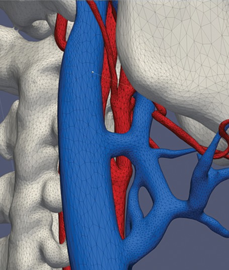
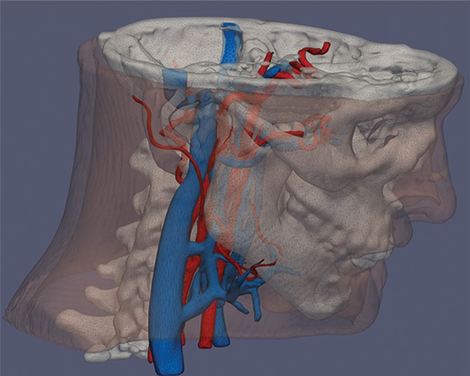
Three-dimensional printing in radiology includes the fabrication of organs depicted on DICOM images. However, 3D printers do not accept DICOM images. Instead, 3D printers understand individual objects (or “parts”) defined by surfaces that enclose a region of space. A standard file format to define these surfaces is Standard Tessellation Language (STL). The STL format defines surfaces as a collection of triangles (called facets) that fit together like a jigsaw puzzle (Fig 1). A newer format called Additive Manufacturing File Format (AMF), which was approved by ASTM International in June 2011, has been designed to overcome many of the limitations of the simple STL format, such as enabling the user to incorporate features including surface texture, color, and material properties into each part (5). This format ideally fits the richness of tissues differentiated with present-day imaging modalities (eg, producing elastic vascular models with embedded plastics to represent calcifications).
Figure 1a.
Process of 3D printing. (a) Individual tissues depicted on DICOM images are segmented (skin and bone from nonenhanced CT images [left two images]; venous and arterial lumina from contrast-enhanced CT images [right two images]). (b, c) The structures are converted to nonoverlapping (b) and triangulated (STL-format) (c) surfaces that enclose the space occupied by each segmented tissue. A 3D printer can then fabricate these “parts,” defined in STL individual files, potentially with different colors or hard or elastic material.
Figure 1c.
Process of 3D printing. (a) Individual tissues depicted on DICOM images are segmented (skin and bone from nonenhanced CT images [left two images]; venous and arterial lumina from contrast-enhanced CT images [right two images]). (b, c) The structures are converted to nonoverlapping (b) and triangulated (STL-format) (c) surfaces that enclose the space occupied by each segmented tissue. A 3D printer can then fabricate these “parts,” defined in STL individual files, potentially with different colors or hard or elastic material.
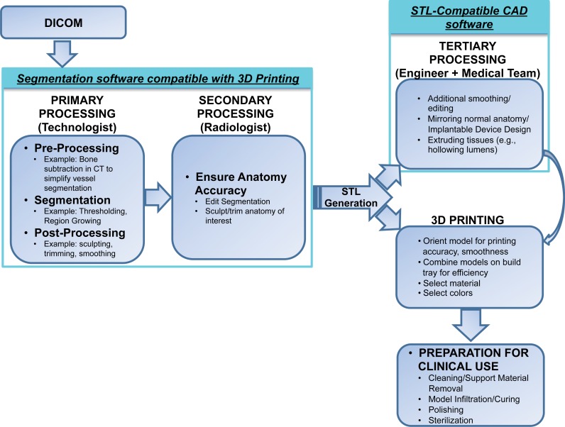
To produce a 3D-printed model, radiologists define objects of interest by separating structures on DICOM images on the basis of tissues and pathophysiology (Fig 1a, 1b; Appendix [online]). These objects, once they are defined in STL format, can be 3D printed. This radiologist-centered process of converting DICOM-format data into STL-format data is a unique new requirement compared with traditional 3D visualization. We conceptually divide the process into three parts: image acquisition, image postprocessing, and 3D printing.
Figure 1b.
Process of 3D printing. (a) Individual tissues depicted on DICOM images are segmented (skin and bone from nonenhanced CT images [left two images]; venous and arterial lumina from contrast-enhanced CT images [right two images]). (b, c) The structures are converted to nonoverlapping (b) and triangulated (STL-format) (c) surfaces that enclose the space occupied by each segmented tissue. A 3D printer can then fabricate these “parts,” defined in STL individual files, potentially with different colors or hard or elastic material.
Image Acquisition
In theory, a 3D medical model can be printed from any volumetric image dataset that has sufficient contrast to differentiate tissues. The imaging data may also be a fusion of images from different (even nonmedical) imaging modalities (Fig 2) (6–8). CT images are most commonly used for 3D printing because of the wide spectrum of applications and relative ease of image postprocessing. The high contrast, signal-to-noise ratio, and spatial resolution enhance structure differentiation and minimize partial volume effects that could limit 3D printing. Image sections should be reconstructed with isotropic voxels of 1.25 mm or less (9). Thicker sections compromise model accuracy, while very thin sections (eg, <0.25 mm) require extensive segmentation and STL refinement (see the section on “Image Postprocessing”), particularly in the presence of image artifact. Cardiac models demonstrate sufficient accuracy with 0.5-mm sections (10), but thin objects such as the orbital floor may require thinner sections (11).
Figure 2.
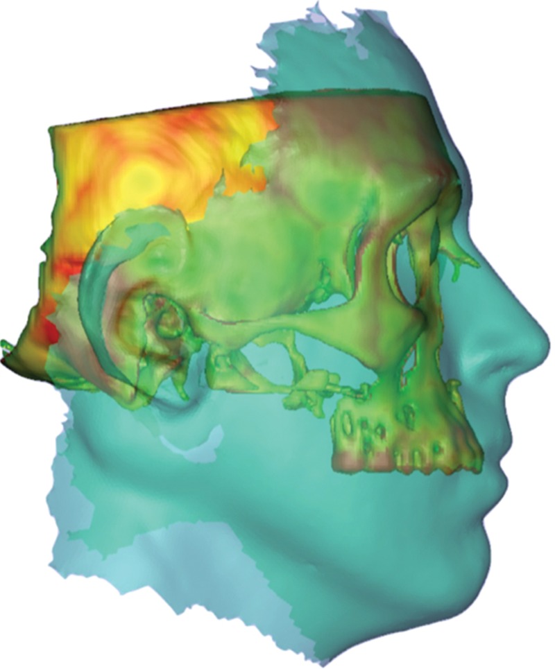
Files for 3D printing (here bone from a CT image) can be combined with a soft-tissue representation (turquoise overlay) acquired from digital photographic methods. Multimodality image registration further enhances the planning of an intervention such as face transplantation by better estimating the relationship between soft tissues and bone. For advanced reconstructive surgeries, these methods are critical for improved functional and cosmetic outcomes.
Image Postprocessing
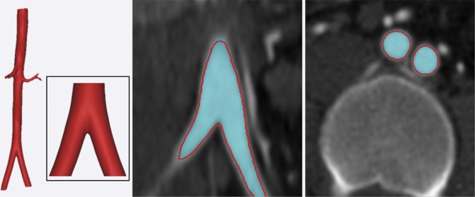
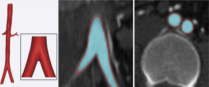
Postprocessing in radiology evolved to visualize volumetric data in any plane and then to render that volume on a 2D display. Manipulating DICOM images for 3D printing involves accurate segmentation of the desired tissues by placing regions of interest (ROIs) around them and then refining the STL representation of the ensemble surface defined by those ROIs (Fig 3). The refinement step is new to radiologists and generally requires specialized software and skills used primarily in engineering applications. The radiologist should carefully review the final STL model against source images for accuracy (Fig 3).
Figure 3a.
Postprocessing of contrast-enhanced CT images of the abdominal aorta. (a) On coronal (middle) and axial (right) CT images, the aorta is segmented by using thresholding (turquoise in a and b), and an enclosing STL surface (3D rendition on left and red outlines in a and b) is generated. (b) On the coronal (middle) and axial (right) CT images, subsequent refinement of the STL file by using standard smoothing and wrapping operations may no longer correctly describe the anatomy.
Figure 3b.
Postprocessing of contrast-enhanced CT images of the abdominal aorta. (a) On coronal (middle) and axial (right) CT images, the aorta is segmented by using thresholding (turquoise in a and b), and an enclosing STL surface (3D rendition on left and red outlines in a and b) is generated. (b) On the coronal (middle) and axial (right) CT images, subsequent refinement of the STL file by using standard smoothing and wrapping operations may no longer correctly describe the anatomy.
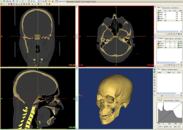
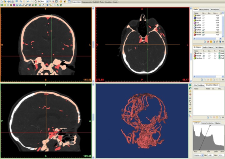
ROI segmentation is both automated (eg, thresholding, edge detection, region growing) and manual. Although thresholding (Appendix [online]) often suffices for CT bone segmentation because the Hounsfield units are higher than in surrounding structures (Fig 4a), more complex algorithms are usually necessary (Fig 4b), such as dynamic adjustment of the thresholding range. For example, CT noise or beam hardening may alter the blood pool attenuation, and if dynamic region growing is not performed, the segmented 3D model of the blood vessel may contain a nonanatomic hole or void. “Wrapping” of a segmented region can also be used to generate a solid model by filling true anatomic voids, such as those in cancellous bone (12,13). Region growing is a useful second step to determine whether segmented voxels belong to one or different parts to be 3D printed. Region growing typically reduces the burden of the final step, which is manual editing (“sculpting”) of the 3D ROIs that surround segmented voxels; this includes manually manipulating ROI boundaries and manually erasing, combining, and modifying parts.
Figure 4a.
Comparison of software environment for 3D printing with visualization tools currently used by radiologists. Screenshots show that generation of an STL file of a skull from CT images uses primarily Hounsfield unit thresholding (a), while more complex structures such as vascular anatomy (b) require use of additional segmentation methods and sculpting.
Figure 4b.
Comparison of software environment for 3D printing with visualization tools currently used by radiologists. Screenshots show that generation of an STL file of a skull from CT images uses primarily Hounsfield unit thresholding (a), while more complex structures such as vascular anatomy (b) require use of additional segmentation methods and sculpting.
After segmentation, most software packages generate a printable 3D STL model of surfaces surrounding segmented tissues on the basis of algorithms that preserve anatomic features, such as interpolation and pattern recognition. The easiest way to understand this step is as follows: Using ROIs, radiologists select voxels that enclose a 3D surface. Conversion of this surface to STL can use any number of triangular facets to fit these surfaces; too few will compromise anatomic features in the 3D-printed model, while too many will lead to unnecessary roughness in the object if the segmented surface is not smooth. In our experience with common clinical scenarios, STL-based models have no benefit once they exceed a given threshold of triangles (Table 1).
Table 1:
Recommended Number of Triangles Used for 3D Printing of Anatomic Models
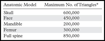
*Finer-detail models (eg, vascular) may require a higher triangle count.
Although most software packages can save the segmentation, process segmented surfaces, and export them as an STL file, the STL conversion is often suboptimal because of segmentation imperfections. For example, a coronary artery CT angiogram segmented as consecutive cross-sectional ROIs defines a surface for volume rendering. However, it cannot be printed because it is “open,” or does not completely enclose a volume of space at the ends or branches; to a 3D printer, this ROI surface has no physical meaning. “Closing” is one example of an STL refinement required for 3D printing. Other manipulations include fixing errors such as holes (eg, gaps between triangular facets) and inverted normals (defining what is inside versus outside the part to be printed) and applying local and/or global smoothing. In this step, the design of additional parts is performed (eg, designing implants or adding supports to hold parts of the printed model in place). Such alterations are unique to 3D printing and separate it from 3D visualization. Software for 3D part manipulation, commonly known as computer-aided design (CAD) or computer-aided manufacturing (CAM) software, and operator expertise are essential for accurate 3D printing. Although adequately trained personnel can perform many steps (Fig 5), adjustments by radiologists are essential to ensure that the model will be clinically useful. Our training resource for radiologists (Appendix [online]) was developed for the 2014 RSNA Annual Meeting and is complemented by initiatives of the U.S. Food and Drug Administration (14) and the National Institutes of Health (15). When the adjustments are complete, the data are transferred to a 3D printing technology, the choice of which is discussed in the following sections.
Figure 5.
Flowchart shows sample workflow for a radiology-centered 3D printing process. DICOM images are initially processed with compatible segmentation software, and the segmented anatomy is reviewed by the radiologist. An STL file of the selected tissues is then generated. The anatomic parts defined in the STL file can be 3D printed or further manipulated with compatible CAD software to, for example, design prostheses or produce a support platform to hold the parts in place. Final preparation of the tangible 3D-printed model (eg, cleaning and sterilization) is required before clinical use.
Three-dimensional Printing
All 3D printers use data encoded in the STL file to deposit and then fuse successive 2D layers of material. This is similar to segmenting a tissue volume by successively identifying 2D ROIs on consecutive cross sections that enclose it. Three-dimensional printing taxonomy and terminology are rapidly evolving, and thus even relatively recent publications use different nomenclature that may cause confusion and miscommunication. This review focuses on a current, commonly accepted classification of 3D printing technologies (16) adopted as ASTM Standard F2792 (17); we suggest the use of this nomenclature to increase the acceptance of medical 3D printing. There are seven groups of specific 3D printing technologies: vat photopolymerization, material jetting, binder jetting, material extrusion, powder bed fusion, sheet lamination, and directed energy deposition.
There are multiple considerations in choosing a printing technology. On one hand, important 3D printing parameters include time required to complete the print, availability, cost of printer and materials, choice of materials, color capabilities, biocompatibility, sterilization capability, material temperature and moisture resistance, transparency, molding or casting properties, and whether a 3D printer with multimaterial capabilities is necessary. On the other hand, the choice of a radiologist’s first 3D printer should largely consider the intended service. This would typically begin with printing for surgical planning only. However, a service that includes printing of custom implants will have a larger scope. Costs of software, hardware, and materials are important factors. This review includes examples where specific material properties influence the choice of one technology over another (18,19). This information is compiled by organ system in the “Clinical Applications” section.
The first five technologies are those most commonly used in medicine. Sheet lamination and directed energy deposition are less common but may show promise in the future. Most technologies include U.S. Pharmacopeial Convention class VI or International Standards Organization 10993 materials, which refer to levels of minimal in vivo biologic reactivity (20). Other than metals, which are available primarily with powder bed fusion and, rarely, material extrusion, few 3D printing materials are approved for implantation. One consideration is model sterilization for both intraoperative use and implantation. Common techniques include high-temperature (ie, steam, flash autoclave), chemical (ie, ethylene oxide, hydrogen peroxide, peracetic acid), and radiation sterilization (21). Generally, printed models, including surgical guides and polymethyl methacrylate (PMMA) implants, require ethylene oxide or other nonheat sterilization such as γ radiation (22). Metal (eg, titanium) powder bed fusion (and potentially nylon [23]) models and some acrylonitrile butadiene styrene (ABS) material extrusion models can withstand autoclaving.
Finally, most 3D printers have inherent spatial resolution that is superior (eg, <50 µm in all axes for material jetting and vat photopolymerization) to that of clinical images. For material extrusion, printing resolution can be comparable to image resolution (0.33 mm), but lower cost and other considerations often render it a useful 3D printing modality.
Vat Photopolymerization.—An example of this technology is the ProJet 7000 printer manufactured by 3D Systems (Rock Hill, SC). The process, more widely known as stereolithography (descriptive video available at http://www.wrnmmc.capmed.mil/ResearchEducation/3DMAC/SitePages/Videos/Stereolithography.aspx) or digital light processing, has three basic components: a high-intensity light source, a vat of photo-curable liquid resin, and a controlling system. Successive 2D layers are sequentially cured by exposing the liquid to a light source, such as a laser, that illuminates only the cross section (ROI) of the model perpendicular to the printer’s z-axis. The resin solidifies on exposure, and by successively lowering or raising (for bottom-up printers) the platform, each layer thickness is solidified until the final layer is complete, after which excess resin is removed and the model undergoes final curing in a UV chamber. Finishing may require smoothing of step edges (light sanding) and application of a UV-resistant sealant. A recently reported digital light processing technology promises to reduce the mechanical steps involved in vat photopolymerization, offering an order of magnitude–faster 3D printing and potentially building a 5-cm-diameter object in less than 10 minutes (24).
Vat photopolymerization is frequently used, particularly for bone. However, materials are relatively expensive (~$210/kg [3D Systems]) and require the vat of material to be maintained at a specific level. Build platform sizes range from less than 12.5 × 12.5 × 12.5 cm to as large as 210 × 70 × 80 cm. Smaller desktop devices are often used to fabricate dental models, dental implant guides, and hearing aids. Postprocessing includes a solvent rinse (generally in an industrial parts washer), manual removal of excess resin or material, and a UV-B light-curing unit, rendering this one of the more labor-intensive methods. Photopolymer materials are relatively fragile, and their appearance ranges from water-clear to opaque white. Newer “ABS-like” materials offer improved mechanical properties. Clear materials allow highlighting of internal structures (eg, nerve spaces, tumors, teeth, plates) by overexposing the material to be highlighted, which darkens or colors it.
Material Jetting.—An example of this technology is the Objet500 Connex printer (Stratasys, Eden Prairie, Minn). It is analogous to ink-jet printing; instead of jetting ink onto paper and allowing it to dry, these devices jet a liquid photopolymer onto a build tray and cure it with UV light. Printers spray layers of the part using two or more jetting heads: one set for the model, and one set for support material. The tray is incrementally lowered layer by layer. The support material is a gel-like or wax material necessary to uphold overhangs and complicated geometries, because an overhang in a model cannot be jetted onto empty space below. The supports are removed by soaking the model in a mild soap solution followed by hand removal, using pressurized water sprays, or melting.
Material jetting utilizes highly versatile material and is well suited for medical models. Materials are relatively expensive (~$300/kg) but are delivered in cartridges for as-needed use. Material expiration, defined by a chip located in the cartridge that alerts the machine to the expiration date and blocks use after that date, poses a limitation. Different-sized platforms have a maximum size of 30 × 18.5 × 20 cm. Model postprocessing includes a solvent rinse (typically mild lye solution) and water blasting of supports. Larger machines enable use of multiple colors and a combination of soft and hard materials; clear models with internal elements such as nerves, teeth, hardware, or tumors can be printed in a more opaque color. Mixing of materials can create models with a variable durometer (hardness) that are flexible (rubberlike), harder, or even rigid. This flexibility, along with the selection of multiple colors that resemble human skin, can be helpful for 3D printing of rehabilitation products. This technology is also used extensively for dental casts and dental implant guides.
Binder Jetting.—An example of this technology is the ProJet 660Pro printer (3D Systems; descriptive video at http://www.wrnmmc.capmed.mil/ResearchEducation/3DMAC/SitePages/Videos/3DPrinting.aspx). This is similar to material jetting, with use of a print head to jet a liquid binding agent onto a bed of fine powder. The binding agent, which can be colored, selectively bonds the powder where deposited. After each layer completion, new powder is deposited for the new layer. Although binder jetting enables creation of color models, translucent models are not possible. Postprocessing includes vacuuming and blowing off unbonded powder and then “infiltration” of the model (with cyanoacrylate, wax, or resin). Infiltration with an elastomer can yield deformable models.
Binder jetting is used extensively in medicine, especially for color coding of anatomy (eg, distinguishing cranial vessels from skull base structures). Materials are relatively less expensive (~$150/kg after infiltration). Support structures are not needed because the model is continuously supported by unbonded powder during fabrication. The largest build platform is roughly 51 × 38 × 23 cm. Because plasterlike materials are generally fragile before infiltration, care must be taken when recovering the printed model to ensure that small pieces are not damaged. The choice of infiltrates determines the final strength of the part, but sealing with cyanoacrylate is generally adequate for most medical models.
Material Extrusion.—An example of this technology is the Fortus 400mc printer (Stratasys; descriptive video at http://www.wrnmmc.capmed.mil/ResearchEducation/3DMAC/SitePages/Videos/FusedDepositModeling.aspx). Material extrusion, previously known as fused deposition modeling, may be the most widespread (including nonmedical printing) and economical hardware; it is used in most at-home machines. Finish quality and resolution are on the lower side. A controlled extrusion head successively deposits layers of a plastic, polymer, or metal on a build platform. Similar to a glue gun, the material, wound on a coil, is unreeled for supply to the extrusion head, which heats it and deposits it on the plane, where it hardens on cooling.
Material extrusion was an early technology applied to medicine; it may be favored by an early 3D printing laboratory because it is overall economical and easy to use. The main materials, thermoplastics such as ABS and polylactide, are specific to the hardware; materials tend to be stronger than those in the previously described technologies and generally cheaper, at less than $100/kg. Build platforms have a maximum dimension of roughly 91 × 61 × 91 cm. Model postprocessing can involve dissolving supports (in a weak lye solution) or manual support removal.
Powder Bed Fusion.—This category includes selective laser sintering, direct metal laser sintering, selective laser melting, and electron beam melting (descriptive video at http://www.wrnmmc.capmed.mil/ResearchEducation/3DMAC/SitePages/Videos/ElectronBeamMelting.aspx). This family of technologies uses a high-power laser or electron beam to fuse small particles of plastic, metal, ceramic, or glass powder into a desired 3D shape. The energy source selectively fuses or melts preheated particles in successive layers on the surface of a powder bed. Like binder jetting, after a layer is fused, the powder bed is lowered by one layer thickness, a new layer is applied on top, and the process is repeated until part completion. Unlike vat photopolymerization and material extrusion processes, some powder bed fusion technologies may not require support structures because the model in progress is continuously surrounded and supported by unsintered powder. However, others require supports to transfer heat away from the part and reduce swelling during the build. The support bed enables powder bed fusion to construct 3D geometries such as a lattice, which is not possible with other methods.
These technologies are used extensively for direct 3D printing of medical devices such as implants and fixations. Models are durable because they use material groups such as thermoplastics and metals such as nylon and titanium alloy. These materials are expensive (>$200/kg). Postprocessing of the printed model depends on the particular modality; for example, heat hardening is used for selective laser melting. Metals fabricated with this method, especially titanium, often require finishing using computer numerical control milling technologies to achieve smooth, polished surfaces.
Other Technologies.—Sheet lamination is an inexpensive method involving the bonding and cutting of paper, metal, or plastic films one layer at a time. Once complete, the part is cleaned by peeling off the excess material. Materials are generally cheaper than in other processes; however, complex parts are difficult to clean, and model production time can be more than double that of other methods. Nonetheless, the recent release of a paper sheet lamination device (MCOR Technologies, Dunlee County, Louth, Ireland) is promising for orthopedic model fabrication, where generally only the bone surface is being evaluated. Required consumable materials generally include paper, glue, and cutting knives, which renders this system one of the least expensive, with a build volume about the size of three reams of letter-size paper. Postprocessing requires labor-intensive peeling away of excess paper. Similar to binder jet models, paper models can be sealed with sealants or wax. This technology continues to improve with respect to fabrication speed and color capabilities.
Directed energy deposition directly deposits material to a location where an energy source is also directed to bond the material. This technology is unique because it can add to or repair an existing part, but to date there have been limited applications in medicine.
Clinical Overview
The growing body of literature supporting medical 3D printing began with early reports (25–27) that demonstrated satisfactory accuracy of models generated from clinical images (28–30). Printed models have occupied an important surgical niche for over a decade, most prominently in maxillofacial applications and recently in intervention planning, among an increasing number of surgeons who recognized its enormous potential and who have established a relationship with radiologists invested in this new modality. New applications are emerging, such as customized medical prostheses, that have greatly affected patient care and are likely to become more readily accessible with the dissemination of 3D printing technology.
Model Accuracy
Discrepancies between segmented anatomy and the 3D-printed model are generally on the order of an imaging voxel size (<1 mm [typically <0.4 mm] and <3% [typically <1%]) (31,32) and usually are clinically negligible. They are most prominent along the section axis of image acquisition and the layer (z-) axis of 3D printers. Use of thinner imaging sections and a narrower z-axis printing layer thickness often mitigates discrepancies.
However, errors can be generated during any step of the process, including image acquisition and postprocessing (33) as well as 3D printing (34,35). Although accuracy of the source images and appropriate choice of printing modality and materials are critical to achieve optimum accuracy (29), image segmentation and STL conversion remain the most error-prone steps. Huotilainen et al (33) reported substantial discrepancies between 3D-printed skull models when a single DICOM dataset was given to three different expert groups. On the basis of our experience, there are two main factors that may reduce errors in this step. First, we suggest that an expert in the field who ideally is a radiologist should perform the image postprocessing. This will ensure that the printed model matches the clinical interpretation of the images, because segmentation accuracy requires proper recognition of structures and their separation from imaging modality artifacts. Second, the segmentation software package plays an important role. There is limited software designed for medical 3D printing, and many visual aids and manipulation tools currently available to radiologists for postprocessing (eg, multiplanar reformations) are notably absent. This paucity should be addressed parallel to the evolution of other aspects of medical 3D printing.
Clinical Applications
We systematically review published reports in an organ-based fashion, focusing on contributions by radiologists to the 3D printing team as well as directions where radiologists can make important contributions as 3D printing is more widely implemented into patient care. Although many modern clinical images can be 3D printed, limitations include costs, time to generate models, and human effort. The applications described are currently used in practice but have not yet been comprehensively reviewed in the literature. Appropriateness and implementation of 3D-printed models into guidelines requires further study, as described in the following sections.
Craniofacial and Maxillofacial
Application of 3D printing to pathologic conditions of the head and neck was among the first medical uses and today remains the most common application (Fig 6). Several studies over the past decade have demonstrated a promising role in dentistry and craniofacial surgeries (Figs 7, 8) (35,36). The majority of applications have been reconstructive, where there is a need for surgical planning and, often, design and fabrication of custom-made implants, prostheses, and surgical guides. Most, if not all, reports have used CT images to print bone structures, and stereolithographic or selective laser sintering technologies to fabricate the models (Table 2), likely because of the hardness of the material, which enables use for contouring and prebending of plates (11,38). Accuracy of the 3D-printed models, which ideally is guaranteed by the radiologist involved in model production, is of paramount importance. Contouring reconstruction plates onto 3D-printed models or directly printing them (Fig 9) saves operating room time and is thought to improve aesthetic outcome (11,38,39,52). Hypothesis-driven assessment of the utility of 3D-printed models for surgical planning in large series of patients has been attempted (36,52) but is marred by the lack of protocols to practically assess utility beyond surgeon satisfaction and self-assessment.
Figure 6.
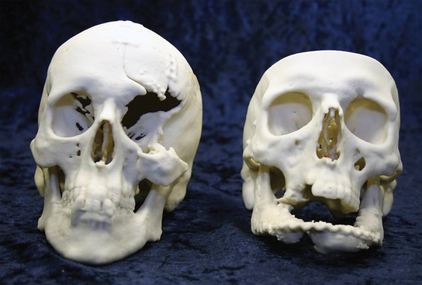
Three-dimensional printed models used for surgical planning in two patients with facial trauma. After the patients were stabilized, steps for surgical planning included creation of a 3D model for optimal visualization of the extent of bone injury.
Figures 7.
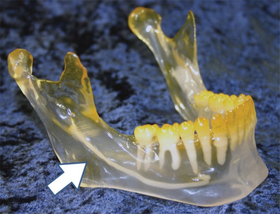
Stereolithographic model of the lower mandible highlights the teeth and the lingual nerve (arrow).
Figures 8.
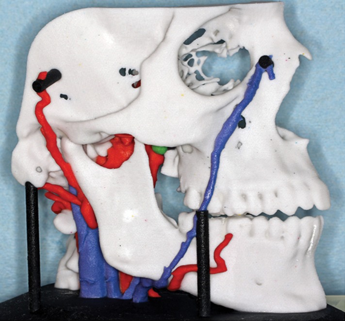
Craniofacial model depicts arteries and veins and is an essential component of planning complex interventions.
Table 2:
Published Craniofacial, Maxillofacial, and Neurosurgical Applications for 3D Printing Technologies
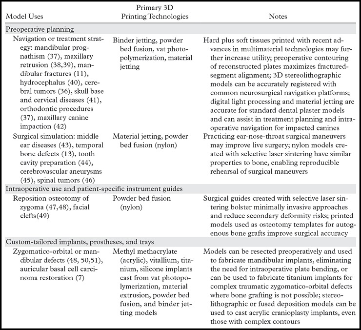
Figure 9.
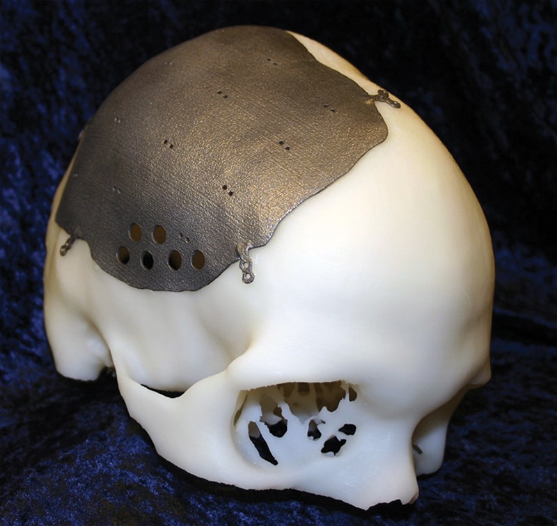
Three-dimensional printed model created for a patient scheduled for placement of a titanium cranial plate. A model of the patient’s skull was printed with stereolithography. The plate (Ti6AlV4 alloy) was 3D printed with electron-beam technology. This type of surgical planning enables a precise, patient-specific intervention that decreases the time required for the intervention and the risk for peri- and postoperative complications.
Three-dimensional printing is an essential tool in the design and testing of complicated or innovative reconstructive surgeries. Our group 3D printed an auricular prosthesis (Fig 10) matched to the patient’s facial structure, with high symmetry compared with the normal ear (7). Three-dimensional printed models have similarly proved essential for full-face transplantation (53), surgical planning (54,55), and follow-up (56). We consider 3D models the best method to select locations for appropriate and optimal osteosynthesis. Similar results for other clinical scenarios (57) have included not only surgical planning, but also rehearsal with standard navigation systems. Furthermore, 3D-printed models may also be useful in restoring donor congruency (Fig 11) for burial (48).
Figure 10a.
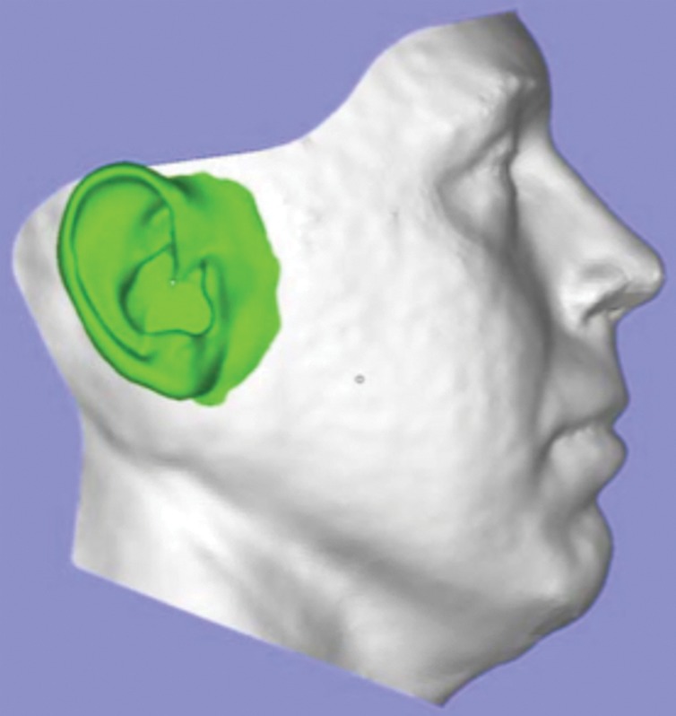
Design and manufacturing of an auricular prosthesis. (a) A representation of the face with a prosthesis is created from digital synthesis of photographs (for the face) and the ear (from DICOM images of the contralateral ear). (b, c) The two pieces of the digital models (b) are used for generation of the definitive silicone prosthesis (c).
Figure 11.
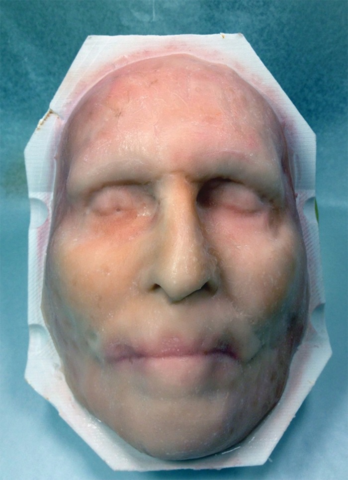
Three-dimensional printed mask used for full-face transplantation. Models are critical for the recipient as well as the donor. In the donor, a 3D mask is used for the benefit of the deceased’s family and loved ones to replace the superficial features of the tissues that become the allograft used to create the new face for the recipient.
Figure 10b.
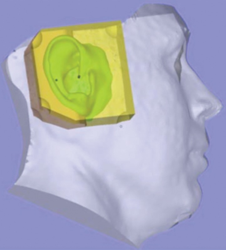
Design and manufacturing of an auricular prosthesis. (a) A representation of the face with a prosthesis is created from digital synthesis of photographs (for the face) and the ear (from DICOM images of the contralateral ear). (b, c) The two pieces of the digital models (b) are used for generation of the definitive silicone prosthesis (c).
Figure 10c.
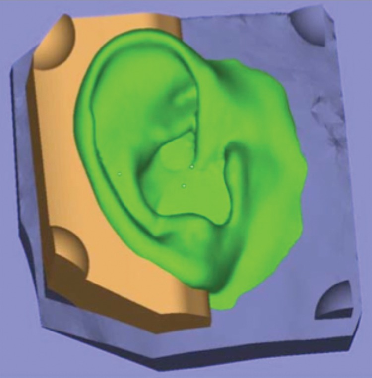
Design and manufacturing of an auricular prosthesis. (a) A representation of the face with a prosthesis is created from digital synthesis of photographs (for the face) and the ear (from DICOM images of the contralateral ear). (b, c) The two pieces of the digital models (b) are used for generation of the definitive silicone prosthesis (c).
Three patients with mandibular pathologic conditions (odontogenic cyst or keratocyst) underwent ablative surgery and postoperative reconstruction, with printed models used not only for planning but also for generation of custom-made implants (50). Printed models have been used preoperatively to design templates for harvesting bone grafts to repair facial clefts (49); in complex maxillofacial and orbital fractures and other complex facial surgeries, models have been used as custom-designed surgical guides (47). Models have also been used to produce individually customized mandibular trays (51) and as casts to fabricate titanium and acrylic cranial (48,59) and dental (42) implants. The process of using a 3D-printed model to sculpt and process PMMA has become important in the treatment of service members with severe head trauma and craniotomies from blast injury at the Walter Reed National Military Medical Center and the National Naval Medical Center. As the techniques have improved, a directly produced implant printed in titanium (Fig 9) is now routinely used.
Virtual surgical planning is a growing field, particularly among dental surgeons (Fig 7) (6) who have embraced cone-beam CT for intervention planning. Printed models enable surgical rehearsal using standard equipment, more precise surgical guides for bone cuts, repositioning, and implant molding and placement. Surgical time is reduced and poor results are minimized. As an example, a surgeon and a dentist planning a final prosthesis can work together with use of customized dental software systems to fabricate an optimal prosthesis for a challenging case.
Neurosurgery
Cerebrovascular models (Table 2; Fig 12) are highly accurate with respect to intraoperative findings and are beneficial for surgical planning, surgical simulation, patient education, and training (41). Printing the skull and blood vessels in different colors (binder jetting) highlights intraoperative anatomic relationships (Fig 13). The printed model can be used to determine the need for embolization, coiling, or clipping (6). For example, a patient-specific distensible cerebral aneurysm model molded in silicone from a 3D-printed model generated from 3D rotational angiographic images included depiction of a wide neck, tortuous access routes, and hypoplastic segments. The model was then used to simulate intervention, including finalizing a surgical approach and strategy and choosing an appropriate device (45). Rigid vat photopolymerization skull models can be used with commercial navigation systems for surgical rehearsal (40, 57). Complex spinal surgery has also benefited from use of 3D-printed models (46).
Figure 12.
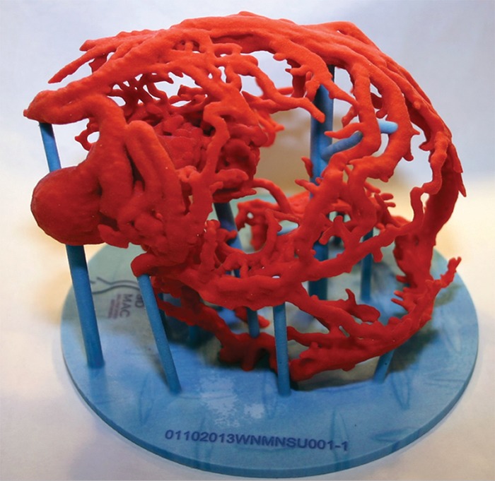
Three-dimensional printed vascular models such as that shown provide unprecedented anatomic and volumetric detail and, in addition to assisting in potential treatment planning, can noninvasively provide details needed to determine a surgical or nonsurgical approach for a complex lesion.
Figure 13.
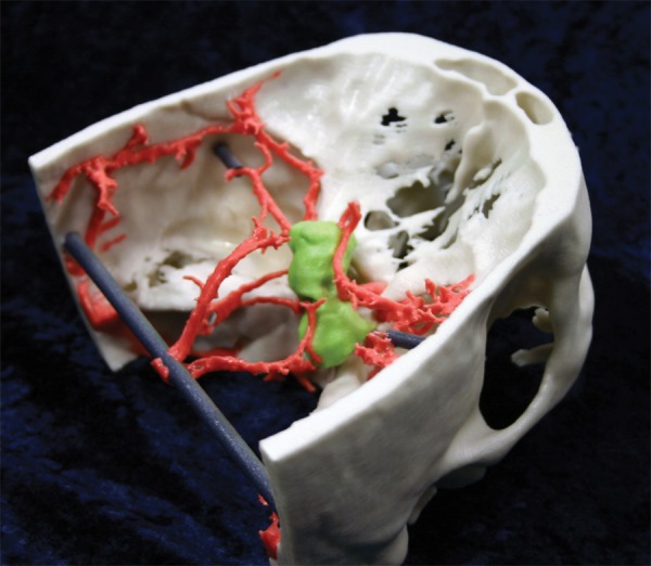
Binder jetting 3D-printed model focuses on a suprasellar mass (green) and uniquely demonstrates the relationship between the critical arterial anatomy and bone.
Thorax
While reports of 3D printing from chest images (Fig 14, Table 3) are sparser than those from head and neck images, a 2-month-old infant with tracheomalacia with difficulty in ventilation successfully received a customized 3D-printed bioresorbable polycaprolactone airway splint (64). In adults, thoracoscopic lobectomy with use of a fissureless technique requires display of the lung beyond current 3D visualization because of the complexity of the airways (61). Three-dimensional printed models augmented the planning of thoracoscopic segmentectomy in a patient with lung cancer, as well as the planning of another thoracoscopic lung surgery in a patient with rare anatomic variations (62). For mediastinal tumor resection, a 3D model provided unique data on the relationship between a thymoma and adjacent structures (62).
Figure 14a.
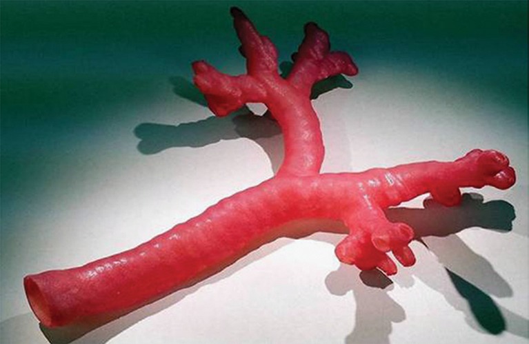
Thoracic 3D-printed model. (a) Three-dimensional printed model of a normal tracheobronchial tree. (b) Fiberoptic view through the bronchus intermedius of the 3D model. (c) Fiberoptic view through the bronchus intermedius in the actual anatomy. Note the similarity between the printed model at simulated bronchoscopy and the actual anatomy. (Fig 14 adapted and reprinted, with permission, from reference 60.)
Table 3:
Published Thoracic Applications for 3D Printing Technologies
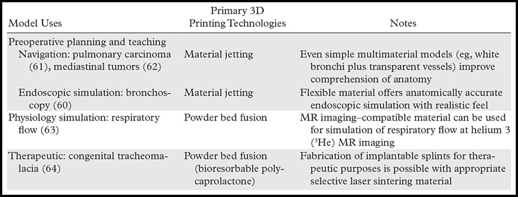
Figure 14b.
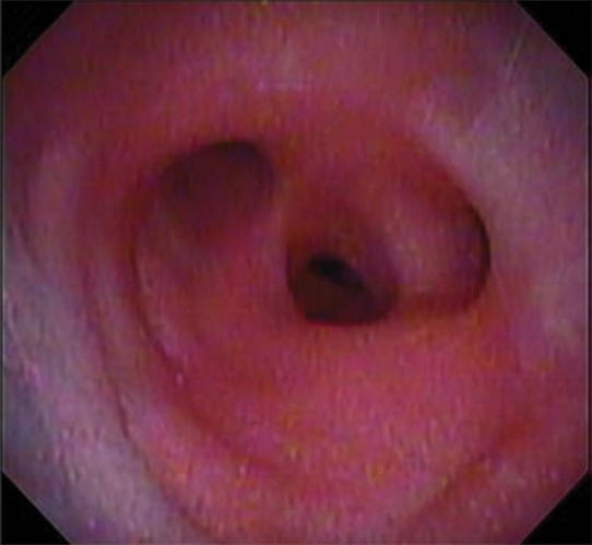
Thoracic 3D-printed model. (a) Three-dimensional printed model of a normal tracheobronchial tree. (b) Fiberoptic view through the bronchus intermedius of the 3D model. (c) Fiberoptic view through the bronchus intermedius in the actual anatomy. Note the similarity between the printed model at simulated bronchoscopy and the actual anatomy. (Fig 14 adapted and reprinted, with permission, from reference 60.)
Figure 14c.
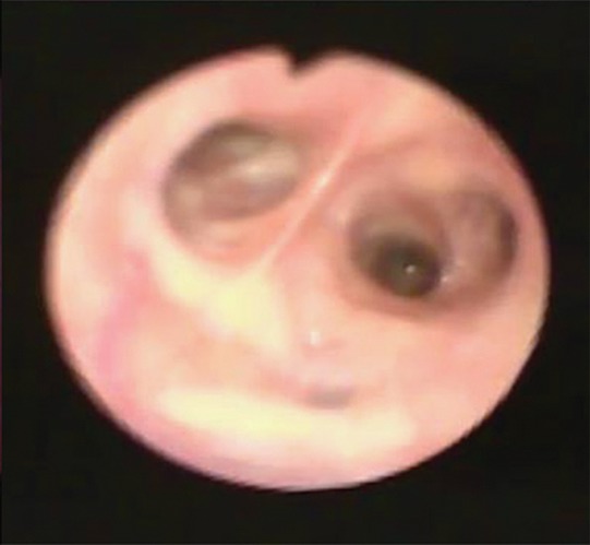
Thoracic 3D-printed model. (a) Three-dimensional printed model of a normal tracheobronchial tree. (b) Fiberoptic view through the bronchus intermedius of the 3D model. (c) Fiberoptic view through the bronchus intermedius in the actual anatomy. Note the similarity between the printed model at simulated bronchoscopy and the actual anatomy. (Fig 14 adapted and reprinted, with permission, from reference 60.)
Cardiovascular
Three-dimensional printing has closed the gap on the unmet need for true 3D visualization in cardiovascular surgical planning, with vascular models likely being the second most common application, next to bone models (Table 4). Source image data are primarily contrast-enhanced MR images and CT images. Various approaches have been used to develop a hollow STL model, including segmenting the blood pool and printing the vessels with binder jetting, followed by infiltration to a limited depth and subsequent breakage and removal of the remaining internal material. More accurate approaches rely on use of CAD software to numerically design a fictitious “wall” to enclose the segmented blood pool (often termed hollowing) or to subtract the STL of the enhanced blood pool from the STL of the surrounding tissues, such as the epicardial boundary. In the latter two approaches, the resulting wall should be printed using a high-resolution technology (material jetting or vat photopolymerization) to achieve a smooth lumen.
Table 4:
Published Cardiovascular Applications for 3D Printing Technologies
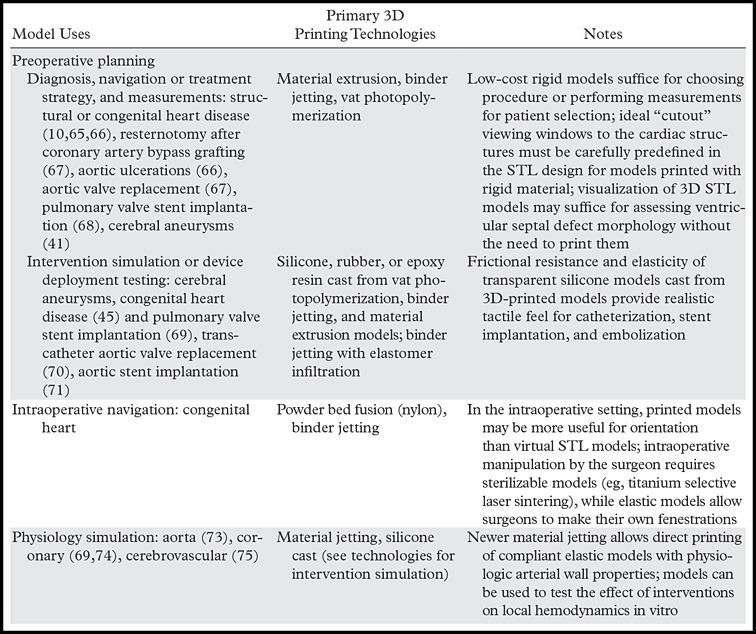
Growing data support the use of models to capture complex anatomy, including congenital heart disease requiring surgery (76). A heart with multiple congenital abnormalities depicted at MR imaging was fabricated at a cost of $364–$810 within 7 hours (72); such models improve spatial orientation, offer better understanding of complex pathologic conditions, and increase surgeon satisfaction (10,65). Applications have included acquired cardiac abnormalities such as ventricular aneurysms and cardiac tumors (10). A 12-patient retrospective feasibility and appropriateness study concluded that 3D-printed models were superior to MR imaging visualization to identify the best candidates for percutaneous pulmonary valve implantation (68). Several authors have suggested more routine use of 3D printing for challenging decisions in cardiac intervention (66,77), particularly as an important strategic initiative for pediatric cardiovascular imagers.
Kim et al (66) reported use of 3D printing in four patients with structural heart disease to plan catheter selection, navigation strategy, and approach to access the aorta. Models have been useful for planning in high-risk valve cases and for intraoperative navigation (67). Håkansson et al (78) designed a silicone model printed in 18 working hours for a cost of €1900 (U.S. $2124) for a patient with a thoracoabdominal aortic aneurysm, with the innovation that calcium was removed for graft sizing by using CAD software. Electrocardiographic-gated CT studies for transcatheter aortic valve replacement planning (70) enable creation of 3D-printed models of the aortic annulus and surrounding structures for potentially safer valve deployment (Fig 15). Incorporation of patient-specific elasticity of the normal versus calcified aorta will likely be an important area of future research.
Figure 15.
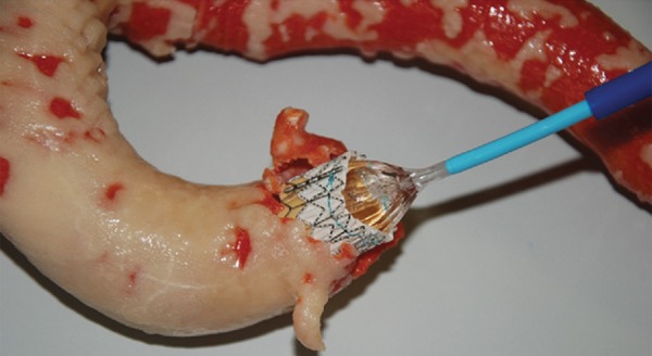
Flexible binder jetting model of a severely calcified aorta used in planning for a transcatheter aortic valve replacement. Red = normal vessel wall, tan = calcium. (Adapted and reprinted, with permission, from reference 70.)
Markl et al (74) used MR imaging to 3D print a solid model of the aortic wall with complex branches (Fig 16), noting that lack of compliance influences the ability to accurately assess blood flow dynamics. Compliant 3D-printed models are, in general, needed for surgical planning (69). Armillotta et al (69) used low-cost material extrusion models of right ventricular outflow to mold a silicone-based, translucent, compliant model to test percutaneous valve stent implantation. Biglino et al (71) directly 3D printed vascular models by using newer material jetting technologies with a rubberlike material (TangoPlus FullCure 930; Objet Geometries, Bellerica, Mass) that mimicked a range of in vivo distensibility by varying the printed vessel wall thickness. These models have been used to test the likelihood of success of insertion of a novel stent-graft for percutaneous pulmonary valve implantation in a patient with a dilated right ventricular outflow tract and severe pulmonary regurgitation.
Figure 16a.
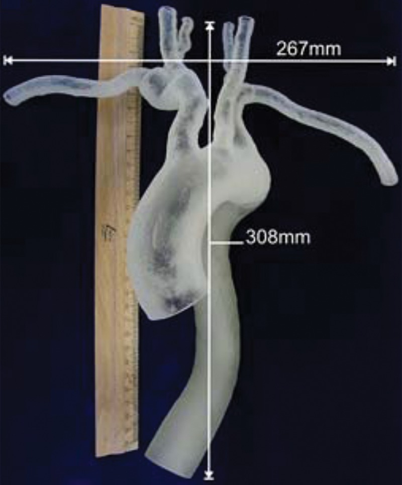
Material jetting model of an aorta, produced by segmentation of images from high-resolution contrast-enhanced MR angiography. (a, b) Full (a) and close-up (b) views of the model show severe kinking and a subclavian artery with a mild aneurysm. (c) Supra-aortic vessel branching (arrows) is seen from inside the model. (Fig 16 adapted and reprinted, with permission, from reference 74.)
Figure 16b.
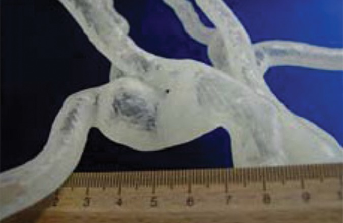
Material jetting model of an aorta, produced by segmentation of images from high-resolution contrast-enhanced MR angiography. (a, b) Full (a) and close-up (b) views of the model show severe kinking and a subclavian artery with a mild aneurysm. (c) Supra-aortic vessel branching (arrows) is seen from inside the model. (Fig 16 adapted and reprinted, with permission, from reference 74.)
Figure 16c.
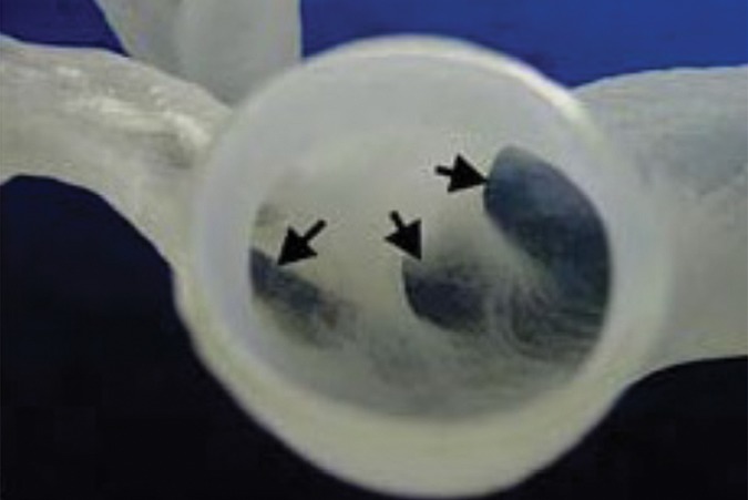
Material jetting model of an aorta, produced by segmentation of images from high-resolution contrast-enhanced MR angiography. (a, b) Full (a) and close-up (b) views of the model show severe kinking and a subclavian artery with a mild aneurysm. (c) Supra-aortic vessel branching (arrows) is seen from inside the model. (Fig 16 adapted and reprinted, with permission, from reference 74.)
Musculoskeletal
Preoperative 3D printing of bone structures has expanded planning and navigation of orthopedic procedures (Figs 17, 18) (79,80) and contributed to novel surgical approaches in osteotomies, fracture fixation, and arthroplasties (79–86) (Table 5). Bagaria et al (81) described 3D-printed models for complex fracture intervention around joints as well as for femoral and calcaneal fractures. Hurson et al (80) used 3D printing to enhance classification of and preoperative planning for acetabular fractures. Although all studies in the musculoskeletal domain conclude that 3D-printed models improve preoperative planning, deliver a superior mechanism to visualize and appreciate the underlying pathologic condition (Fig 19), and can effectively educate patients and the medical care team, 3D printing may be unnecessary for some applications. Specifically, limiting the use of 3D-printed models to diagnostic or classification purposes may be an attractive but unnecessary supplement. For example, in a series of 30 calcaneal fractures, Kacl et al (27) found no statistically significant increase in accuracy for detection of relevant features with use of printed models compared with 3D visualization.
Figures 17a.
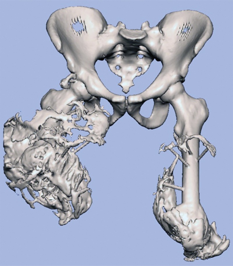
Heterotopic ossification. (a) Surface rendering of an STL model of the pelvis and femurs. (b) Three-dimensional printed model helps define the surgical approach and treatment plan before the procedure, leading to a more rapid procedure with fewer complications.
Figures 18.
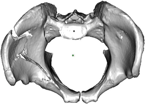
Surface rendering of an STL model of a complex pelvic fracture. Note that both femurs were removed to enhance fracture visualization for intervention planning.
Table 5:
Published Musculoskeletal Applications for 3D Printing Technologies
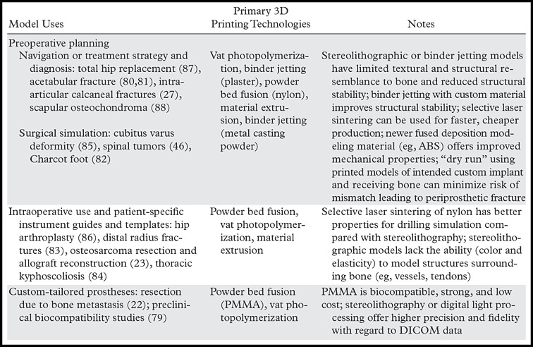
Figure 19.
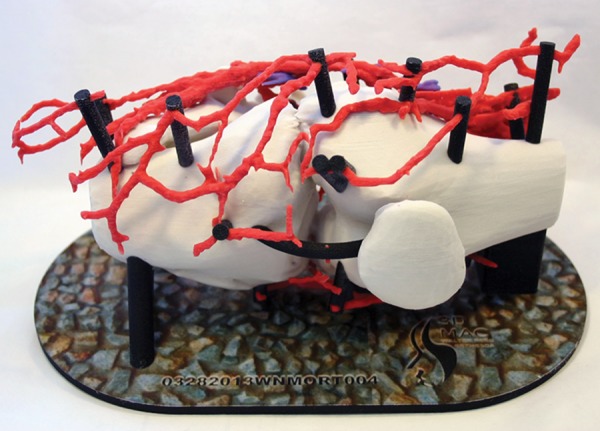
Three-dimensional printed model of a knee includes the vasculature to assist in planning for intervention.
Figures 17b.
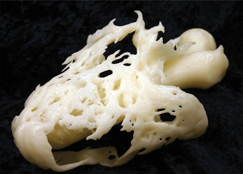
Heterotopic ossification. (a) Surface rendering of an STL model of the pelvis and femurs. (b) Three-dimensional printed model helps define the surgical approach and treatment plan before the procedure, leading to a more rapid procedure with fewer complications.
Indispensable applications include design of patient-specific instrument guides (Fig 20), templates for intraoperative use (83,86), and virtual preoperative simulation or intraoperative navigation (81,82,84). For patients with unilateral disease, CAD software can be used to effectively mirror normal anatomy on the unaffected side to obtain a tangible 3D model onto which guides toward the ideal outcome can be produced (83). This advantage, similar to the mirroring described earlier in this article for cranial implants (7), is readily leveraged by the CAD software–centric workflow of 3D printing. Surgical oncology has also benefitted from the ability to better delineate resection margins (88); printed models have been used to deliver patient-specific guides for bone tumor resection and to develop a matching 3D-printed model for cutting an allograft precisely fitted to the resection gap (23).
Figure 20.

Three-dimensional printed model of a complex fracture. For this patient, commercially available hardware (silver) was prebent and shaped on the basis of the printed model. This saves considerable intraoperative time and cost when compared with standard procedures, where the hardware choices are determined at standard CT, in the operating room, or typically with a combination of both.
Prostheses and Non-facial Reconstructive Surgeries
Despite the availability of multiple standardized commercial implants, some patients fall outside the window of available devices and benefit from design and production of individually tailored prostheses and splints. Customized bone and soft-tissue prostheses can potentially be 3D printed from a variety of biocompatible materials (12,50,89,90). Electron-beam melting offers the possibility of directly producing titanium and cobalt prostheses that are custom designed numerically for the patient to ensure even force distribution toward reduced implant wear and better clinical outcomes (12).
Faur et al (87) screened 346 patients with degenerative changes of the hip joint and 3D printed both the femoral structure and the custom prosthetic implant to validate the implant design for one patient with an extremely narrow medullary canal for whom available femoral implants did not fit. Pruksakorn et al (22) 3D printed endoprostheses for the palliative care of 16 patients who required reconstructive surgery focused on metastases to the humerus and ulna. The endoprostheses were fabricated from PMMA using selective laser sintering and were sterilized with γ radiation. At a median follow-up of 486 days, the functional outcome was good in almost 70% of patients and fair in the remaining patients. As reconstructive and restorative surgeries have advanced in scope and complexity, incorporation of 3D printing stands to offer better functional outcomes and better prosthesis longevity than are currently possible (12). However, this will require further technology maturation and strong partnerships between radiologists and surgeons.
Radiation Oncology
Optimum planning for radiation therapy must consider distortion of the normal anatomy by tumor, as well as irregular tissue surfaces. Three-dimensional printing may address, at least in part, these challenges. Sun and Wu (91) reported the use of a cranium that was 3D printed from CT images so that the patient’s various treatment options could be tested. Zemnick et al (92) presented a 3D-printed patient-specific extraoral radiation shield that was comfortable for the patient and enabled homogeneous delivery of radiation for skin cancer treatment despite the patient’s uneven superficial tissue topography.
Bioprinting
Bioprinting refers to the utilization of 3D printing and 3D printing–like techniques to combine cells, growth factors, and biomaterials to fabricate biomedical parts that maximally imitate natural tissue characteristics (93). Emerging innovations span from printing of tissues and partially viable organs to fully functional viable organs (94). With use of technologies beyond the scope of this review (94), cells or extracellular matrix are deposited to a 3D gel layer by layer to produce the desired tissue or organ. Challenges now being addressed by tissue engineering and developmental biology researchers are geared toward development of viable and functional organs, including the ability to assemble tissues without a need for support materials, allow proper cell-to-cell interactions, and provide tissue vascularization (95). Preliminary reports include printing of skin tissue with humanlike morphology and histology (96), fabrication of cardiac tissue (97), and evaluation of the possibility of creating bioartificial livers with the help of 3D printing techniques (98). In the already-emerging field of patient-specific prostheses, bioprinting directions include the marriage of the solid 3D-printed models discussed earlier (eg, tibial and femoral implants) with integration of viable cartilage constructs (90).
Bioprinting can also exceed the “biologic specifications” of organs, enabling the incorporation of electronic apparatuses into living tissues to create “bionic” organs. Mannoor et al (99) successfully used 3D printing to fabricate a bionic ear composed of living cells and electronic nanoparticles. The cells demonstrated viability in various stages of the study, and the electronic components allowed the ear to receive signals in the hertz to gigahertz range.
Although tissue and organ printing are overall considered feasible and highly promising, routine clinical use has yet to be realized. Input from radiologists has been minimal during the engineering phases of these developments because there is little, if any, need to use imaging in developing experimental tissues. However, radiologists should prepare to become important contributors who put these technologies to work when they are ready—for example, in the design of patient-specific organs, similar to radiologists’ contribution to current 3D printing of patient-specific prostheses.
Other Applications
Although there is a large potential for radiologists to expand abdominal imaging and intervention with 3D printing, reports to date are relatively limited and focus largely on abdominal surgery. Three-dimensional printed models of the liver plus vascular and biliary structures assisted in preoperative planning and intraoperative orientation in three living-donor liver transplant surgeries (100). There is an increasing need for liver transplantation, with a relative lack of cadaver donors, and lobectomy in healthy living donors is marred by morbidity (101). In this context, both donors and patients can benefit from the reported higher accuracy of volumetric measurements from preoperative 3D-printed models compared with source CT images (100). In a pilot study, Silberstein et al (102) 3D printed the kidneys plus a renal tumor in five patients who were candidates for partial nephrectomy. In addition to their use for intraoperative navigation, the 3D-printed models enhanced the understanding of patients and their families regarding the goals of their surgery, leading to higher satisfaction in the choice of treatment plan.
Three-dimensional printing can also positively affect the presentation of medicolegal data. Ebert et al (103) suggested the use of 3D-printed models to convey forensic medicine results from MR imaging and CT in the courtroom, and Schievano et al (104) used postmortem MR imaging to fabricate 3D-printed models of 11 fetuses and infants and envisioned, among other applications, better understanding of complex congenital abnormalities and opportunities for intrauterine diagnosis and management and more appropriate counseling of parents after pregnancy termination. In a series of 33 fetuses, Werner et al (8) established the possibility of generating fetal 3D-printed models by using 3D ultrasonography (US) in conjunction with MR imaging or CT when an abnormality was present to convey a range of fetal abnormalities such as conjoined twins, skeletal and central nervous system abnormalities, and facial and thoracic defects.
Education
Three-dimensional models are proven tools for educating medical students and house officers, although there is no literature to our knowledge that focuses specifically on radiology education. Although learning of complex geometries in human anatomy has been facilitated with 3D visualization methods and novel educational applications (105), there is little dispute that physical models provide an optimal tool to learn anatomy (106). The cost is favorable when compared with that of cadaveric materials, and normal anatomic variations can be readily demonstrated. In the training of medical students (8,102), 3D models can supplement and, in theory, replace cadaveric material, which is increasingly difficult to obtain (103.104). In terms of residency training, substantial groundwork is being laid in the surgical arena; Waran et al (40) successfully registered 3D-printed cranial models with two commercial navigation platforms and carried out common navigation maneuvers and surgery, thus opening the avenue for their use as neurosurgical training tools. Three-dimensional printed models have also been used for training in cerebrovascular aneurysm repair (107), transapical aortic valve replacement (108), repair of abdominal aortic aneurysms (Fig 21) (109), and percutaneous nephrolithotomy (110). A middle ear surgery simulator that integrates both soft and hard materials was judged by an expert panel of otologists to have high fidelity that could translate to improvement in live surgery (43), and a standard stereolithographic 3D-printed model of the temporal bone exhibited similar properties to those of real bone during use of a surgical drill, bur, and suction irrigator (13). Bustamante et al (60) replicated the tracheobronchial tree of two patients, envisioning an educational tool for variants of tracheobronchial anatomy in which fiberoptic bronchoscopy could also be performed to improve lung isolation skills.
Figure 21a.

Three-dimensional printed model of the aortic lumen used for training. (a) Silicon model was produced by molding onto a solid model of the aortic lumen that was reproduced with binder jetting. The 3D-printed solid lumen model used as the mold core was broken for removal from the cured silicone layer. (b) Image shows fluoroscopically guided catheterization and stent placement performed on the elastic silicone model. (Fig 21 adapted and reprinted, with permission, from reference 78.)
Figure 21b.
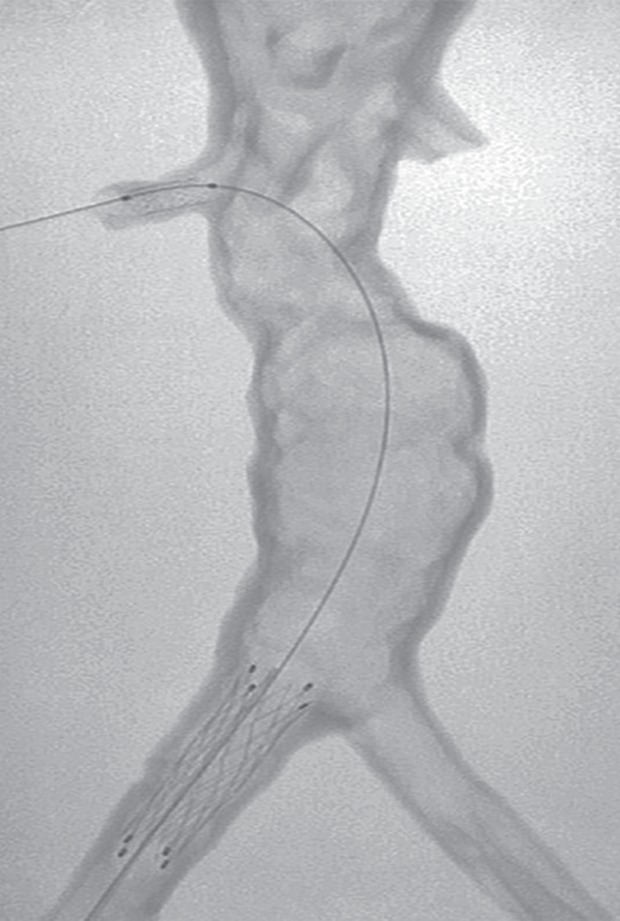
Three-dimensional printed model of the aortic lumen used for training. (a) Silicon model was produced by molding onto a solid model of the aortic lumen that was reproduced with binder jetting. The 3D-printed solid lumen model used as the mold core was broken for removal from the cured silicone layer. (b) Image shows fluoroscopically guided catheterization and stent placement performed on the elastic silicone model. (Fig 21 adapted and reprinted, with permission, from reference 78.)
Hypothesis-driven studies using trainees as subjects have reported high satisfaction in operative dentistry, where 40 students used 3D-printed models versus standard schematics and photographs for cavity preparation (44). Printed models have enhanced the learning performance of veterinary students (111). Wilasrusmee et al (109) tested the ability of 43 1st- to 5th-year general surgery trainees to plan for four cases of endovascular aortic aneurysm repair and found that trainees who used both a 3D-printed model and CT angiography agreed with expert opinion significantly and consistently more than those who used only CT. In general, it appears that at all levels of expertise, 3D-printed models deliver expanded training opportunities, and for surgeons, the models build confidence and enhance efficiency in the operating room.
Research in Flow Physiology
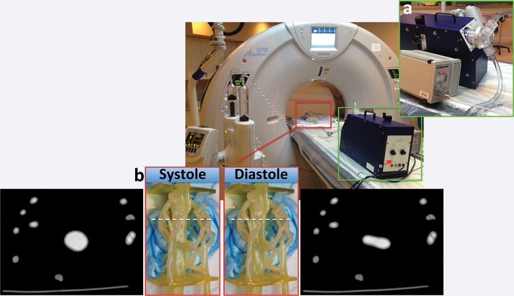
Three-dimensional printed models expand investigations in functional CT and MR imaging that are not otherwise feasible with human subjects because of radiation burden, imaging time, and monetary costs. Repeatable experiments with use of vascular phantoms derived from rotational digital subtraction angiography, CT (Fig 22), and MR imaging (17,73) data capitalize on the ability to 3D print hollow structures with different properties. Early work used 3D printing for negative molds (ie, using the solid printed blood pool as a mold for silicone) (112). Although this remains useful for percutaneous intervention simulation (Table 4), direct 3D printing of hollow vascular models can now faithfully produce a realistic, compliant vessel wall (Fig 23, Movie) that can be within 120 µm of the STL model (17).
Figure 22a.
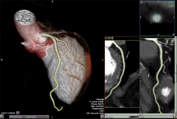
Three-dimensional printed phantom used for CT angiographic experiments. (a) In vivo CT angiograms show segmentation of the left anterior descending coronary artery and first and second diagonal branches. (b) An STL model of the luminal surface (turquoise) was created and was augmented with flow diffusers (red) and an outer shell (transparent gray) fitted with Luer locks. The space between the lumen and outer shell was then printed with a vat photopolymerization machine. (c) The finished 3D-printed phantom can be used for “in vitro” contrast-enhanced CT angiographic experiments.
Figure 23.
Newer material jetting 3D printing technologies and materials allow direct printing of a compliant vessel wall (2–3 mm thickness) with sufficient tensile strength to be used for realistic flow physiology experiments. Images show an in vitro contrast-enhanced CT angiographic experiment performed by using a pulsatile flow pump and ultrasonic flowmeter (green inset a) attached to a coronary phantom (red inset b), which was fabricated by segmentation of a patient’s contrast-enhanced CT angiograms. The lower panel shows the phantom and CT angiograms obtained in two cardiac phases (systole, left; diastole, right) (Movie). (Experiment performed in collaboration with Ciprian Ionita, PhD, and Steven Rudin, PhD, State University of New York at Buffalo, Buffalo, NY.)
Figure 22b.
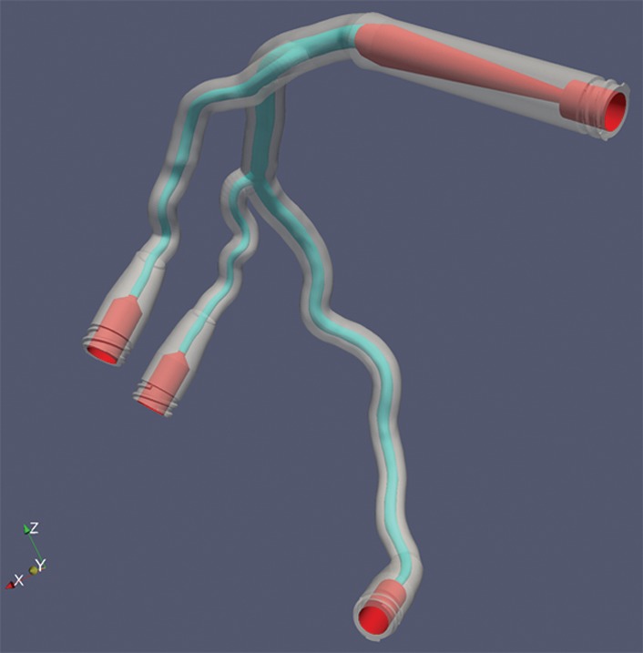
Three-dimensional printed phantom used for CT angiographic experiments. (a) In vivo CT angiograms show segmentation of the left anterior descending coronary artery and first and second diagonal branches. (b) An STL model of the luminal surface (turquoise) was created and was augmented with flow diffusers (red) and an outer shell (transparent gray) fitted with Luer locks. The space between the lumen and outer shell was then printed with a vat photopolymerization machine. (c) The finished 3D-printed phantom can be used for “in vitro” contrast-enhanced CT angiographic experiments.
Figure 22c.
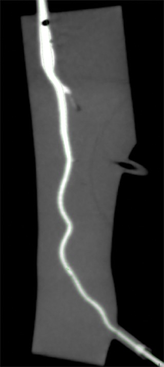
Three-dimensional printed phantom used for CT angiographic experiments. (a) In vivo CT angiograms show segmentation of the left anterior descending coronary artery and first and second diagonal branches. (b) An STL model of the luminal surface (turquoise) was created and was augmented with flow diffusers (red) and an outer shell (transparent gray) fitted with Luer locks. The space between the lumen and outer shell was then printed with a vat photopolymerization machine. (c) The finished 3D-printed phantom can be used for “in vitro” contrast-enhanced CT angiographic experiments.
Movie.
Newer material jetting 3D printing technologies and materials allow direct printing of a compliant vessel wall (2–3 mm thickness) with sufficient tensile strength to be used for realistic flow physiology experiments. In the CT angiographic experiment shown, a pulsatile flow pump and ultrasonic flowmeter (green inset a) are attached to a coronary phantom (red inset b) that was fabricated by segmentation of a patient’s contrast-enhanced coronary CT angiograms.
Current research (71) to optimize printed vascular model compliance will enhance insight gained from in vitro flow experiments (113), while concurrent in silico (computer-simulated) computational fluid dynamics experiments using STL models from patient data will yield substantial new knowledge and help optimize in vivo imaging techniques such as flow-encoded MR imaging (73), coronary contrast opacification gradients (114), and respiratory dynamics using 3He MR imaging (63). Interventions can similarly benefit; 3D printing of the airways in the nasal cavity has been used to estimate in vitro the differences in air velocity between inspiration and expiration, as well as intercycle vortices toward enhancing nasal operations (115). In the cardiovascular arena, 3D-printed models have been used toward understanding and optimizing the use of stents in difficult coronary bifurcation lesions (116).
Conclusion
Successful 3D printing from radiologic images is multidisciplinary; accurate models that represent patient anatomy and pathologic processes require close interaction between radiologists and referring physicians. In addition to implant fabrication, the role of 3D-printed models from DICOM images continues to expand and is fueled by the growing realization that intraoperative utilization of 3D images is not as efficient as having a physical model identical to patient structures, particularly for highly complex interventions. Further reductions in morbidity, mortality, and operating room time (36,37) are inevitable. However, further, organized, prospective data supporting improved outcomes with use of 3D printing are instrumental for development of guidelines and, ultimately, for reimbursement.
To date, much of our knowledge of 3D printing has been shared among small circles of experts, and publications largely focus on individual cases, with variable reporting. We propose that a format be adopted to enhance communication regarding the reporting of 3D-printed models. This would include all of the following data, if available: printer type, materials, time required to print (assuming the object was printed by itself), estimated cost of materials, and potential overall cost to fabricate the model. The reporting should also include details regarding print layer thickness, modality of the source images (eg, CT), and DICOM section thickness.
Armed with these data for a growing literature, radiologists can begin to amass knowledge, experience, and insights to make 3D printing a reality to better serve patients whose care will benefit from handheld models.
APPENDIX
For this journal-based SA-CME activity, the authors, editor, and reviewers have disclosed no relevant relationships.
Funding: The work was supported by the National Institutes of Health [grant number EB015868]. The views expressed in this article are those of the authors and do not necessarily reflect the official policy, position, or endorsement of the Departments of the Navy, Army, or Defense or the U.S. Government.
Abbreviations:
- ABS
- acrylonitrile butadiene styrene
- CAD
- computer-aided design
- DICOM
- Digital Imaging and Communications in Medicine
- PMMA
- polymethyl methacrylate
- ROI
- region of interest
- RSNA
- Radiological Society of North America
- STL
- Standard Tessellation Language
- 3D
- three-dimensional
- 2D
- two-dimensional
References
- 1.Fishman EK, Drebin B, Magid D, et al. Volumetric rendering techniques: applications for three-dimensional imaging of the hip. Radiology 1987;163(3):737–738. [DOI] [PubMed] [Google Scholar]
- 2.Rubin GD, Dake MD, Napel SA, McDonnell CH, Jeffrey RB, Jr. Three-dimensional spiral CT angiography of the abdomen: initial clinical experience. Radiology 1993;186(1): 147–152. [DOI] [PubMed] [Google Scholar]
- 3.Wohlers Associates, Inc . Wohlers report 2013: additive manufacturing and 3D printing state of the industry. Fort Collins, Colo: Wohlers Associates, Inc, 2013. [Google Scholar]
- 4.Mitsouras D, Dill KE, Kumamaru KK, Steigner ML, Rybicki FJ, III. 3-D printing: bridging the gap between theory and practice [abstr]. In: Radiological Society of North America Scientific Assembly and Annual Meeting Program. Oak Brook, Ill: Radiological Society of North America, 2013; 109. [Google Scholar]
- 5.Hiller J, Lipson H. STL 2.0: a proposal for a universal multi-material Additive Manufacturing File format. Proceedings of the Solid Freeform Fabrication Symposium 2009. Austin, Texas, 2009; 266–278. [Google Scholar]
- 6.Grant GT, Liacouras P, Kondor S. Maxillofacial imaging in the trauma patient. Atlas Oral Maxillofac Surg Clin North Am 2013;21(1):25–36. [DOI] [PubMed] [Google Scholar]
- 7.Liacouras P, Garnes J, Roman N, Petrich A, Grant GT. Designing and manufacturing an auricular prosthesis using computed tomography, 3-dimensional photographic imaging, and additive manufacturing: a clinical report. J Prosthet Dent 2011;105(2):78–82. [DOI] [PubMed] [Google Scholar]
- 8.Werner H, dos Santos JR, Fontes R, et al. Additive manufacturing models of fetuses built from three-dimensional ultrasound, magnetic resonance imaging and computed tomography scan data. Ultrasound Obstet Gynecol 2010;36(3): 355–361. [DOI] [PubMed] [Google Scholar]
- 9.Mahesh M. Search for isotropic resolution in CT from conventional through multiple-row detector. RadioGraphics 2002;22(4):949–962. [DOI] [PubMed] [Google Scholar]
- 10.Jacobs S, Grunert R, Mohr FW, Falk V. 3D-imaging of cardiac structures using 3D heart models for planning in heart surgery: a preliminary study. Interact Cardiovasc Thorac Surg 2008;7(1):6–9. [DOI] [PubMed] [Google Scholar]
- 11.Kozakiewicz M, Elgalal M, Loba P, et al. Clinical application of 3D pre-bent titanium implants for orbital floor fractures. J Craniomaxillofac Surg 2009;37(4):229–234. [DOI] [PubMed] [Google Scholar]
- 12.Harrysson OL, Hosni YA, Nayfeh JF. Custom-designed orthopedic implants evaluated using finite element analysis of patient-specific computed tomography data: femoral-component case study. BMC Musculoskelet Disord 2007;8:91. [DOI] [PMC free article] [PubMed] [Google Scholar]
- 13.Suzuki M, Ogawa Y, Kawano A, Hagiwara A, Yamaguchi H, Ono H. Rapid prototyping of temporal bone for surgical training and medical education. Acta Otolaryngol 2004;124(4):400–402. [DOI] [PubMed] [Google Scholar]
- 14.U.S. Food and Drug Administration . Public workshop: additive manufacturing of medical devices—an interactive discussion on the technical considerations of 3D printing. http://www.fda.gov/MedicalDevices/NewsEvents/WorkshopsConferences/ucm397324.htm. Published 2014. Accessed February 2, 2015.
- 15.U.S. Department of Health and Human Services–National Institutes of Health . NIH 3D print exchange 2015. http://3dprint.nih.gov. Published 2015. Accessed February 2, 2015.
- 16.Huang Y, Leu MC. NSF additive manufacturing workshop report. NSF Workshop on Frontiers of Additive Manufacturing Research and Education. Arlington, Va: University of Florida Center for Manufacturing Innovation, 2013. [Google Scholar]
- 17.ASTM . F2792–12a standard terminology for additive manufacturing technologies. In: Electronics; declarable substances in materials; 3D imaging systems. West Conshohocken, Pa: ASTM, 2014. [Google Scholar]
- 18.Stevens B, Yang Y, Mohandas A, Stucker B, Nguyen KT. A review of materials, fabrication methods, and strategies used to enhance bone regeneration in engineered bone tissues. J Biomed Mater Res B Appl Biomater 2008;85(2):573–582. [DOI] [PubMed] [Google Scholar]
- 19.Starosolski ZA, Kan JH, Rosenfeld SD, Krishnamurthy R, Annapragada A. Application of 3-D printing (rapid prototyping) for creating physical models of pediatric orthopedic disorders. Pediatr Radiol 2014;44(2):216–221. [DOI] [PubMed] [Google Scholar]
- 20.U.S. Food and Drug Administration . Use of International Standard ISO-10993, “Biological Evaluation of Medical Devices Part 1: Evaluation and Testing” (replaces #G87–1 #8294) (blue book memo). Silver Spring, Md: U.S. Food and Drug Administration, 2013. [Google Scholar]
- 21.Rutala WA, Weber DJ. Guidelines for disinfection and sterilization in healthcare facilities. Centers for Disease Control and Prevention. http://www.cdc.gov/hicpac/pdf/guidelines/disinfection_nov_2008.pdf. Published 2008. Accessed October 18, 2014. [Google Scholar]
- 22.Pruksakorn D, Chantarapanich N, Arpornchayanon O, Leerapun T, Sitthiseripratip K, Vatanapatimakul N. Rapid-prototype endoprosthesis for palliative reconstruction of an upper extremity after resection of bone metastasis. Int J CARS 2015;10(3):343–350. [DOI] [PubMed] [Google Scholar]
- 23.Bellanova L, Paul L, Docquier PL. Surgical guides (patient-specific instruments) for pediatric tibial bone sarcoma resection and allograft reconstruction. Sarcoma 2013;2013:787653. [DOI] [PMC free article] [PubMed] [Google Scholar]
- 24.Tumbleston JR, Shirvanyants D, Ermoshkin N, et al. Additive manufacturing: continuous liquid interface production of 3D objects. Science 2015;347(6228):1349–1352. [DOI] [PubMed] [Google Scholar]
- 25.D’Urso PS, Earwaker WJ, Barker TM, et al. Custom cranioplasty using stereolithography and acrylic. Br J Plast Surg 2000;53(3):200–204. [DOI] [PubMed] [Google Scholar]
- 26.McGurk M, Amis AA, Potamianos P, Goodger NM. Rapid prototyping techniques for anatomical modelling in medicine. Ann R Coll Surg Engl 1997;79(3):169–174. [PMC free article] [PubMed] [Google Scholar]
- 27.Kacl GM, Zanetti M, Amgwerd M, et al. Rapid prototyping (stereolithography) in the management of intra-articular calcaneal fractures. Eur Radiol 1997;7(2):187–191. [DOI] [PubMed] [Google Scholar]
- 28.Nizam A, Gopal RN, Naing L, Hakim AB, Samsudin AR. Dimensional accuracy of the skull models produced by rapid prototyping technology using stereolithography apparatus. Arch Orofac Sci 2006;1:60–66. [Google Scholar]
- 29.Salmi M, Paloheimo KS, Tuomi J, Wolff J, Mäkitie A. Accuracy of medical models made by additive manufacturing (rapid manufacturing). J Craniomaxillofac Surg 2013;41(7):603–609. [DOI] [PubMed] [Google Scholar]
- 30.Waran V, Devaraj P, Hari Chandran T, et al. Three-dimensional anatomical accuracy of cranial models created by rapid prototyping techniques validated using a neuronavigation station. J Clin Neurosci 2012;19(4):574–577. [DOI] [PubMed] [Google Scholar]
- 31.Ibrahim D, Broilo TL, Heitz C, et al. Dimensional error of selective laser sintering, three-dimensional printing and PolyJet models in the reproduction of mandibular anatomy. J Craniomaxillofac Surg 2009;37(3):167–173. [DOI] [PubMed] [Google Scholar]
- 32.Taft RM, Kondor S, Grant GT. Accuracy of rapid prototype models for head and neck reconstruction. J Prosthet Dent 2011;106(6):399–408. [DOI] [PubMed] [Google Scholar]
- 33.Huotilainen E, Jaanimets R, Valášek J, et al. Inaccuracies in additive manufactured medical skull models caused by the DICOM to STL conversion process. J Craniomaxillofac Surg 2014;42(5):e259–e265. [DOI] [PubMed] [Google Scholar]
- 34.Choi JY, Choi JH, Kim NK, et al. Analysis of errors in medical rapid prototyping models. Int J Oral Maxillofac Surg 2002;31(1):23–32. [DOI] [PubMed] [Google Scholar]
- 35.Hazeveld A, Huddleston Slater JJ, Ren Y. Accuracy and reproducibility of dental replica models reconstructed by different rapid prototyping techniques. Am J Orthod Dentofacial Orthop 2014;145(1):108–115. [DOI] [PubMed] [Google Scholar]
- 36.D’Urso PS, Barker TM, Earwaker WJ, et al. Stereolithographic biomodelling in cranio-maxillofacial surgery: a prospective trial. J Craniomaxillofac Surg 1999;27(1):30–37. [DOI] [PubMed] [Google Scholar]
- 37.Mavili ME, Canter HI, Saglam-Aydinatay B, Kamaci S, Kocadereli I. Use of three-dimensional medical modeling methods for precise planning of orthognathic surgery. J Craniofac Surg 2007;18(4):740–747. [DOI] [PubMed] [Google Scholar]
- 38.Cui J, Chen L, Guan X, Ye L, Wang H, Liu L. Surgical planning, three-dimensional model surgery and preshaped implants in treatment of bilateral craniomaxillofacial post-traumatic deformities. J Oral Maxillofac Surg 2014;72(6):e1–e14. [DOI] [PubMed] [Google Scholar]
- 39.Wagner JD, Baack B, Brown GA, Kelly J. Rapid 3-dimensional prototyping for surgical repair of maxillofacial fractures: a technical note. J Oral Maxillofac Surg 2004;62(7):898–901. [DOI] [PubMed] [Google Scholar]
- 40.Waran V, Pancharatnam D, Thambinayagam HC, et al. The utilization of cranial models created using rapid prototyping techniques in the development of models for navigation training. J Neurol Surg A Cent Eur Neurosurg 2014;75(1):12–15. [DOI] [PubMed] [Google Scholar]
- 41.Wurm G, Tomancok B, Pogady P, Holl K, Trenkler J. Cerebrovascular stereolithographic biomodeling for aneurysm surgery: technical note. J Neurosurg 2004;100(1):139–145. [DOI] [PubMed] [Google Scholar]
- 42.Faber J, Berto PM, Quaresma M. Rapid prototyping as a tool for diagnosis and treatment planning for maxillary canine impaction. Am J Orthod Dentofacial Orthop 2006;129(4):583–589. [DOI] [PubMed] [Google Scholar]
- 43.Monfared A, Mitteramskogler G, Gruber S, Salisbury JK, Jr, Stampfl J, Blevins NH. High-fidelity, inexpensive surgical middle ear simulator. Otol Neurotol 2012;33(9):1573–1577. [DOI] [PubMed] [Google Scholar]
- 44.Soares PV, de Almeida Milito G, Pereira FA, et al. Rapid prototyping and 3D-virtual models for operative dentistry education in Brazil. J Dent Educ 2013;77(3):358–363. [PubMed] [Google Scholar]
- 45.Kono K, Shintani A, Okada H, Terada T. Preoperative simulations of endovascular treatment for a cerebral aneurysm using a patient-specific vascular silicone model. Neurol Med Chir (Tokyo) 2013;53(5):347–351. [DOI] [PubMed] [Google Scholar]
- 46.Paiva WS, Amorim R, Bezerra DA, Masini M. Aplication of the stereolithography technique in complex spine surgery. Arq Neuropsiquiatr 2007;65(2B):443–445. [DOI] [PubMed] [Google Scholar]
- 47.Herlin C, Koppe M, Béziat JL, Gleizal A. Rapid prototyping in craniofacial surgery: using a positioning guide after zygomatic osteotomy—a case report. J Craniomaxillofac Surg 2011;39(5):376–379. [DOI] [PubMed] [Google Scholar]
- 48.Li J, Li P, Lu H, et al. Digital design and individually fabricated titanium implants for the reconstruction of traumatic zygomatico-orbital defects. J Craniofac Surg 2013;24(2):363–368. [DOI] [PubMed] [Google Scholar]
- 49.Wang J, Liu JF, Liu W, Wang JC, Wang SY, Gui L. Application of computer techniques in repair of oblique facial clefts with outer-table calvarial bone grafts. J Craniofac Surg 2013;24(3):957–960. [DOI] [PubMed] [Google Scholar]
- 50.Arora A, Datarkar AN, Borle RM, Rai A, Adwani DG. Custom-made implant for maxillofacial defects using rapid prototype models. J Oral Maxillofac Surg 2013;71(2):e104–e110. [DOI] [PubMed] [Google Scholar]
- 51.Zhou LB, Shang HT, He LS, et al. Accurate reconstruction of discontinuous mandible using a reverse engineering/computer-aided design/rapid prototyping technique: a preliminary clinical study. J Oral Maxillofac Surg 2010;68(9):2115–2121. [DOI] [PubMed] [Google Scholar]
- 52.Müller A, Krishnan KG, Uhl E, Mast G. The application of rapid prototyping techniques in cranial reconstruction and preoperative planning in neurosurgery. J Craniofac Surg 2003;14(6):899–914. [DOI] [PubMed] [Google Scholar]
- 53.Pomahac B, Pribaz J, Eriksson E, et al. Three patients with full facial transplantation. N Engl J Med 2012;366(8):715–722. [DOI] [PubMed] [Google Scholar]
- 54.Soga S, Ersoy H, Mitsouras D, et al. Surgical planning for composite tissue allotransplantation of the face using 320-detector row computed tomography. J Comput Assist Tomogr 2010;34(5):766–769. [DOI] [PubMed] [Google Scholar]
- 55.Soga S, Pomahac B, Mitsouras D, et al. Preoperative vascular mapping for facial allotransplantation: four-dimensional computed tomographic angiography versus magnetic resonance angiography. Plast Reconstr Surg 2011;128(4):883–891. [DOI] [PubMed] [Google Scholar]
- 56.Kumamaru KK, Sisk GC, Mitsouras D, et al. Vascular communications between donor and recipient tissues after successful full face transplantation. Am J Transplant 2014;14(3):711–719. [DOI] [PubMed] [Google Scholar]
- 57.Bullock P, Dunaway D, McGurk L, Richards R. Integration of image guidance and rapid prototyping technology in craniofacial surgery. Int J Oral Maxillofac Surg 2013;42(8): 970–973. [DOI] [PubMed] [Google Scholar]
- 58.Grant GT, Liacouras P, Santiago GF, et al. Restoration of the donor face after facial allotransplantation: digital manufacturing techniques. Ann Plast Surg 2014;72(6):720–724. [DOI] [PMC free article] [PubMed] [Google Scholar]
- 59.Gronet PM, Waskewicz GA, Richardson C. Preformed acrylic cranial implants using fused deposition modeling: a clinical report. J Prosthet Dent 2003;90(5):429–433. [DOI] [PubMed] [Google Scholar]
- 60.Bustamante S, Bose S, Bishop P, Klatte R, Norris F. Novel application of rapid prototyping for simulation of bronchoscopic anatomy. J Cardiothorac Vasc Anesth 2014;28(4): 1134–1137. [DOI] [PubMed] [Google Scholar]
- 61.Akiba T, Nakada T, Inagaki T. Simulation of the fissureless technique for thoracoscopic segmentectomy using rapid prototyping. Ann Thorac Cardiovasc Surg 2015;21(1):84–86. [DOI] [PMC free article] [PubMed] [Google Scholar]
- 62.Akiba T, Nakada T, Inagaki T. A three-dimensional mediastinal model created with rapid prototyping in a patient with ectopic thymoma. Ann Thorac Cardiovasc Surg 2015;21(1):87–89. [DOI] [PMC free article] [PubMed] [Google Scholar]
- 63.Giesel FL, Mehndiratta A, von Tengg-Kobligk H, et al. Rapid prototyping raw models on the basis of high resolution computed tomography lung data for respiratory flow dynamics. Acad Radiol 2009;16(4):495–498. [DOI] [PubMed] [Google Scholar]
- 64.Zopf DA, Hollister SJ, Nelson ME, Ohye RG, Green GE. Bioresorbable airway splint created with a three-dimensional printer. N Engl J Med 2013;368(21):2043–2045. [DOI] [PubMed] [Google Scholar]
- 65.Riesenkampff E, Rietdorf U, Wolf I, et al. The practical clinical value of three-dimensional models of complex congenitally malformed hearts. J Thorac Cardiovasc Surg 2009;138(3):571–580. [DOI] [PubMed] [Google Scholar]
- 66.Kim MS, Hansgen AR, Wink O, Quaife RA, Carroll JD. Rapid prototyping: a new tool in understanding and treating structural heart disease. Circulation 2008;117(18):2388–2394. [DOI] [PubMed] [Google Scholar]
- 67.Sodian R, Schmauss D, Markert M, et al. Three-dimensional printing creates models for surgical planning of aortic valve replacement after previous coronary bypass grafting. Ann Thorac Surg 2008;85(6):2105–2108. [DOI] [PubMed] [Google Scholar]
- 68.Schievano S, Migliavacca F, Coats L, et al. Percutaneous pulmonary valve implantation based on rapid prototyping of right ventricular outflow tract and pulmonary trunk from MR data. Radiology 2007;242(2):490–497. [DOI] [PubMed] [Google Scholar]
- 69.Armillotta A, Bonhoeffer P, Dubini G, et al. Use of rapid prototyping models in the planning of percutaneous pulmonary valved stent implantation. Proc Inst Mech Eng H 2007;221(4):407–416. [DOI] [PubMed] [Google Scholar]
- 70.Schmauss D, Schmitz C, Bigdeli AK, et al. Three-dimensional printing of models for preoperative planning and simulation of transcatheter valve replacement. Ann Thorac Surg 2012;93(2):e31–e33. [DOI] [PubMed] [Google Scholar]
- 71.Biglino G, Verschueren P, Zegels R, Taylor AM, Schievano S. Rapid prototyping compliant arterial phantoms for in-vitro studies and device testing. J Cardiovasc Magn Reson 2013;15:2. [DOI] [PMC free article] [PubMed] [Google Scholar]
- 72.Mottl-Link S, Hübler M, Kühne T, et al. Physical models aiding in complex congenital heart surgery. Ann Thorac Surg 2008;86(1):273–277. [DOI] [PubMed] [Google Scholar]
- 73.Canstein C, Cachot P, Faust A, et al. 3D MR flow analysis in realistic rapid-prototyping model systems of the thoracic aorta: comparison with in vivo data and computational fluid dynamics in identical vessel geometries. Magn Reson Med 2008;59(3):535–546. [DOI] [PubMed] [Google Scholar]
- 74.Markl M, Schumacher R, Küffer J, Bley TA, Hennig J. Rapid vessel prototyping: vascular modeling using 3T magnetic resonance angiography and rapid prototyping technology. MAGMA 2005;18(6):288–292. [DOI] [PubMed] [Google Scholar]
- 75.Ionita CN, Mokin M, Varble N, et al. Challenges and limitations of patient-specific vascular phantom fabrication using 3D Polyjet printing. In: Molthen RC, Weaver JB, eds. Proceedings of SPIE: medical imaging 2014—biomedical applications in molecular, structural, and functional imaging. Vol 9038. Bellingham, Wash: SPIE, 2014; 90380M. [DOI] [PMC free article] [PubMed] [Google Scholar]
- 76.Markert M, Weber S, Lueth TC. A beating heart model 3D printed from specific patient data. Conf Proc IEEE Eng Med Biol Soc 2007;2007:4472–4775. [DOI] [PubMed] [Google Scholar]
- 77.Kim MS, Hansgen AR, Carroll JD. Use of rapid prototyping in the care of patients with structural heart disease. Trends Cardiovasc Med 2008;18(6):210–216. [DOI] [PubMed] [Google Scholar]
- 78.Håkansson A, Rantatalo M, Hansen T, Wanhainen A. Patient specific biomodel of the whole aorta: the importance of calcified plaque removal. Vasa 2011;40(6):453–459. [DOI] [PubMed] [Google Scholar]
- 79.Gittard SD, Narayan RJ, Lusk J, et al. Rapid prototyping of scaphoid and lunate bones. Biotechnol J 2009;4(1):129–134. [DOI] [PubMed] [Google Scholar]
- 80.Hurson C, Tansey A, O’Donnchadha B, Nicholson P, Rice J, McElwain J. Rapid prototyping in the assessment, classification and preoperative planning of acetabular fractures. Injury 2007;38(10):1158–1162. [DOI] [PubMed] [Google Scholar]
- 81.Bagaria V, Deshpande S, Rasalkar DD, Kuthe A, Paunipagar BK. Use of rapid prototyping and three-dimensional reconstruction modeling in the management of complex fractures. Eur J Radiol 2011;80(3):814–820. [DOI] [PubMed] [Google Scholar]
- 82.Giovinco NA, Dunn SP, Dowling L, et al. A novel combination of printed 3-dimensional anatomic templates and computer-assisted surgical simulation for virtual preoperative planning in Charcot foot reconstruction. J Foot Ankle Surg 2012;51(3):387–393. [DOI] [PubMed] [Google Scholar]
- 83.Kunz M, Ma B, Rudan JF, Ellis RE, Pichora DR. Image-guided distal radius osteotomy using patient-specific instrument guides. J Hand Surg Am 2013;38(8):1618–1624. [DOI] [PubMed] [Google Scholar]
- 84.Yang JC, Ma XY, Lin J, Wu ZH, Zhang K, Yin QS. Personalised modified osteotomy using computer-aided design–rapid prototyping to correct thoracic deformities. Int Orthop 2011;35(12):1827–1832. [DOI] [PMC free article] [PubMed] [Google Scholar]
- 85.Zhang YZ, Lu S, Chen B, Zhao JM, Liu R, Pei GX. Application of computer-aided design osteotomy template for treatment of cubitus varus deformity in teenagers: a pilot study. J Shoulder Elbow Surg 2011;20(1):51–56. [DOI] [PubMed] [Google Scholar]
- 86.Du H, Tian XX, Li TS, et al. Use of patient-specific templates in hip resurfacing arthroplasty: experience from sixteen cases. Int Orthop 2013;37(5):777–782. [DOI] [PMC free article] [PubMed] [Google Scholar]
- 87.Faur C, Crainic N, Sticlaru C, Oancea C. Rapid prototyping technique in the preoperative planning for total hip arthroplasty with custom femoral components. Wien Klin Wochenschr 2013;125(5-6):144–149. [DOI] [PubMed] [Google Scholar]
- 88.Tam MD, Laycock SD, Bell D, Chojnowski A. 3-D printout of a DICOM file to aid surgical planning in a 6 year old patient with a large scapular osteochondroma complicating congenital diaphyseal aclasia. J Radiol Case Rep 2012;6(1):31–37. [DOI] [PMC free article] [PubMed] [Google Scholar]
- 89.Grant GT, Taft RM, Wheeler ST. Practical application of polyurethane and Velcro in maxillofacial prosthetics. J Prosthet Dent 2001;85(3):281–283. [DOI] [PubMed] [Google Scholar]
- 90.Woodfield TB, Guggenheim M, von Rechenberg B, Riesle J, van Blitterswijk CA, Wedler V. Rapid prototyping of anatomically shaped, tissue-engineered implants for restoring congruent articulating surfaces in small joints. Cell Prolif 2009;42(4):485–497. [DOI] [PMC free article] [PubMed] [Google Scholar]
- 91.Sun SP, Wu CJ. Using the full scale 3D solid anthropometric model in radiation oncology positioning and verification. Conf Proc IEEE Eng Med Biol Soc 2004;5:3432–3435. [DOI] [PubMed] [Google Scholar]
- 92.Zemnick C, Woodhouse SA, Gewanter RM, Raphael M, Piro JD. Rapid prototyping technique for creating a radiation shield. J Prosthet Dent 2007;97(4):236–241. [DOI] [PubMed] [Google Scholar]
- 93.Melchels FP, Domingos MA, Klein TJ, Malda J, Bartolo PJ, Hutmacher DW. Additive manufacturing of tissues and organs. Prog Polym Sci 2012;37(8):1079–1104. [Google Scholar]
- 94.Ozbolat IT, Yu Y. Bioprinting toward organ fabrication: challenges and future trends. IEEE Trans Biomed Eng 2013;60(3):691–699. [DOI] [PubMed] [Google Scholar]
- 95.Mironov V, Boland T, Trusk T, Forgacs G, Markwald RR. Organ printing: computer-aided jet-based 3D tissue engineering. Trends Biotechnol 2003;21(4):157–161. [DOI] [PubMed] [Google Scholar]
- 96.Lee V, Singh G, Trasatti JP, et al. Design and fabrication of human skin by three-dimensional bioprinting. Tissue Eng Part C Methods 2014;20(6):473–484. [DOI] [PMC free article] [PubMed] [Google Scholar]
- 97.Gaetani R, Doevendans PA, Metz CH, et al. Cardiac tissue engineering using tissue printing technology and human cardiac progenitor cells. Biomaterials 2012;33(6):1782–1790. [DOI] [PubMed] [Google Scholar]
- 98.Wang X, Yan Y, Zhang R. Rapid prototyping as a tool for manufacturing bioartificial livers. Trends Biotechnol 2007;25(11):505–513. [DOI] [PubMed] [Google Scholar]
- 99.Mannoor MS, Jiang Z, James T, et al. 3D printed bionic ears. Nano Lett 2013;13(6):2634–2639. [DOI] [PMC free article] [PubMed] [Google Scholar]
- 100.Zein NN, Hanouneh IA, Bishop PD, et al. Three-dimensional print of a liver for preoperative planning in living donor liver transplantation. Liver Transpl 2013;19(12):1304–1310. [DOI] [PubMed] [Google Scholar]
- 101.Soejima Y, Shimada M, Suehiro T, et al. Outcome analysis in adult-to-adult living donor liver transplantation using the left lobe. Liver Transpl 2003;9(6):581–586. [DOI] [PubMed] [Google Scholar]
- 102.Silberstein JL, Maddox MM, Dorsey P, Feibus A, Thomas R, Lee BR. Physical models of renal malignancies using standard cross-sectional imaging and 3-dimensional printers: a pilot study. Urology 2014;84(2):268–272. [DOI] [PubMed] [Google Scholar]
- 103.Ebert LC, Thali MJ, Ross S. Getting in touch: 3D printing in forensic imaging. Forensic Sci Int 2011;211(1-3):e1–e6. [DOI] [PubMed] [Google Scholar]
- 104.Schievano S, Sebire NJ, Robertson NJ, Taylor AM, Thayyil S. Reconstruction of fetal and infant anatomy using rapid prototyping of post-mortem MR images. Insights Imaging 2010;1(4):281–286. [DOI] [PMC free article] [PubMed] [Google Scholar]
- 105.Petersson H, Sinkvist D, Wang C, Smedby O. Web-based interactive 3D visualization as a tool for improved anatomy learning. Anat Sci Educ 2009;2(2):61–68. [DOI] [PubMed] [Google Scholar]
- 106.Valdecasas AG, Correas AM, Guerrero CR, Juez J. Understanding complex systems: lessons from Auzoux’s and von Hagens’s anatomical models. J Biosci 2009;34(6):835–843. [DOI] [PubMed] [Google Scholar]
- 107.Wurm G, Lehner M, Tomancok B, Kleiser R, Nussbaumer K. Cerebrovascular biomodeling for aneurysm surgery: simulation-based training by means of rapid prototyping technologies. Surg Innov 2011;18(3):294–306. [DOI] [PubMed] [Google Scholar]
- 108.Abdel-Sayed P, Kalejs M, von Segesser LK. A new training set-up for trans-apical aortic valve replacement. Interact Cardiovasc Thorac Surg 2009;8(6):599–601. [DOI] [PubMed] [Google Scholar]
- 109.Wilasrusmee C, Suvikrom J, Suthakorn J, et al. Three-dimensional aortic aneurysm model and endovascular repair: an educational tool for surgical trainees. Int J Angiol 2008;17(3):129–133. [DOI] [PMC free article] [PubMed] [Google Scholar]
- 110.Bruyère F, Leroux C, Brunereau L, Lermusiaux P. Rapid prototyping model for percutaneous nephrolithotomy training. J Endourol 2008;22(1):91–96. [DOI] [PubMed] [Google Scholar]
- 111.Preece D, Williams SB, Lam R, Weller R. “Let’s get physical”: advantages of a physical model over 3D computer models and textbooks in learning imaging anatomy. Anat Sci Educ 2013;6(4):216–224. [DOI] [PubMed] [Google Scholar]
- 112.Knox K, Kerber CW, Singel SA, Bailey MJ, Imbesi SG. Stereolithographic vascular replicas from CT scans: choosing treatment strategies, teaching, and research from live patient scan data. AJNR Am J Neuroradiol 2005;26(6): 1428–1431. [PMC free article] [PubMed] [Google Scholar]
- 113.Cao P, Duhamel Y, Olympe G, Ramond B, Langevin F. A new production method of elastic silicone carotid phantom based on MRI acquisition using rapid prototyping technique. Conf Proc IEEE Eng Med Biol Soc 2013;2013:5331–5334. [DOI] [PubMed] [Google Scholar]
- 114.Steigner ML, Mitsouras D, Whitmore AG, et al. Iodinated contrast opacification gradients in normal coronary arteries imaged with prospectively ECG-gated single heart beat 320-detector row computed tomography. Circ Cardiovasc Imaging 2010;3(2):179–186. [DOI] [PMC free article] [PubMed] [Google Scholar]
- 115.Chung SK, Son YR, Shin SJ, Kim SK. Nasal airflow during respiratory cycle. Am J Rhinol 2006;20(4):379–384. [DOI] [PubMed] [Google Scholar]
- 116.Mortier P, De Beule M, Dubini G, Hikichi Y, Murasato Y, Ormiston JA. Coronary bifurcation stenting: insights from in vitro and virtual bench testing. EuroIntervention 2010;6(Suppl J):J53–J60. [DOI] [PubMed] [Google Scholar]
Associated Data
This section collects any data citations, data availability statements, or supplementary materials included in this article.


