Abstract
There have been significant advances in the field of echocardiography with the introduction of a number of new techniques into standard clinical practice. Consequently, a ‘standard’ echocardiographic examination has evolved to become a more detailed and time-consuming examination that requires a high level of expertise. This Guideline produced by the British Society of Echocardiography (BSE) Education Committee aims to provide a minimum dataset that should be obtained in a comprehensive standard echocardiogram. In addition, the layout proposes a recommended sequence in which to acquire the images. If abnormal pathology is detected, additional views and measurements should be obtained with reference to other BSE protocols when appropriate. Adherence to these recommendations will promote an increased quality of echocardiography and facilitate accurate comparison of studies performed either by different operators or at different departments.
Keywords: transthoracic echocardiography, 2D echocardiography, guidelines
Introduction
This Guideline aims to provide a framework for performing an adult transthoracic echocardiogram (TTE) and replaces the previous minimum datasets published. This current Guideline differs from the 2005 dataset in outlining the views and measures recommended in a fully comprehensive TTE, and in addition recognises that such studies may not be performed in all circumstances. The layout proposes a recommended sequence on how to perform a comprehensive TTE.
‘Minimum requirements’ are depicted in bold text and identify the views and measurements that should be performed in all subjects being scanned for the first time ‘recommendations’ are depicted in italics and together with the minimum requirements form the basis of a comprehensive examination. Wherever possible, a comprehensive study comprising all the views and measurements in this Guideline outlined in black italics and bold font text should be performed, provided the views and measurements can be obtained reliably. It is understood that not all the measurements in the minimum requirements dataset will be performed in all follow-up studies. It is also understood that not all measurements in the minimum requirements will be performed in focused or target studies, for example check pericardial effusion.
Both minimum requirements and recommendations may only be sufficient when the echocardiographic study is entirely normal. If abnormalities are detected, additional views may be required to supplement those outlined in the dataset.
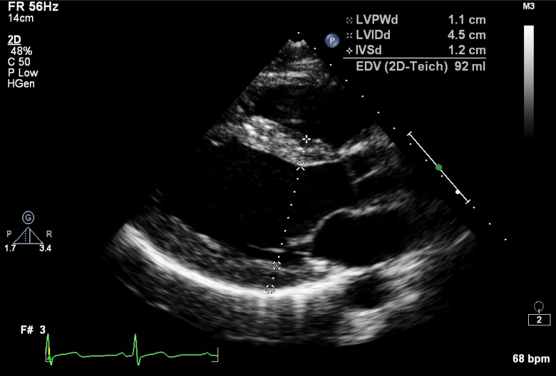
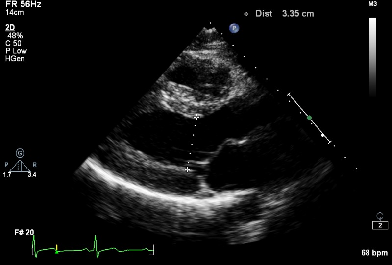
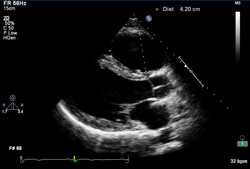
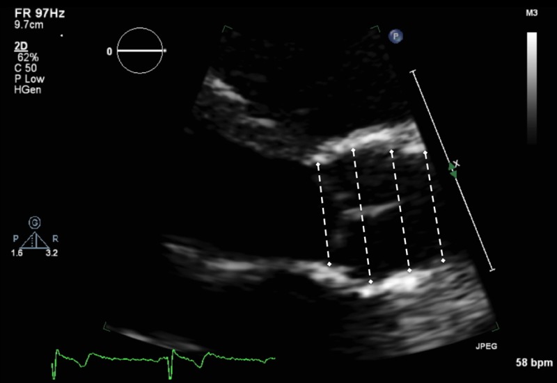
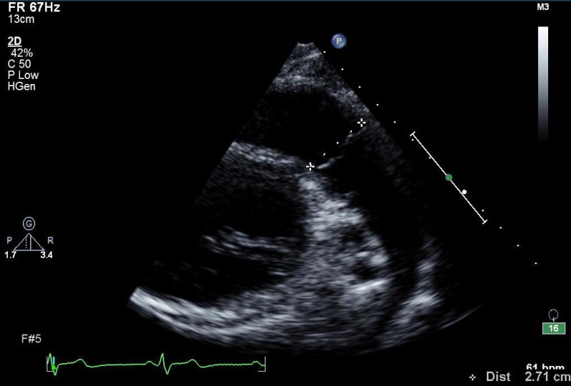
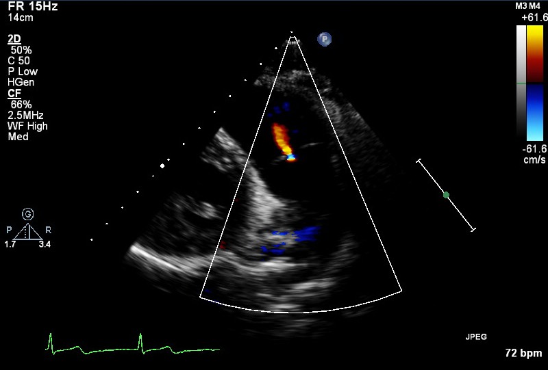
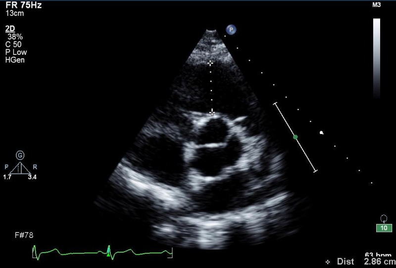
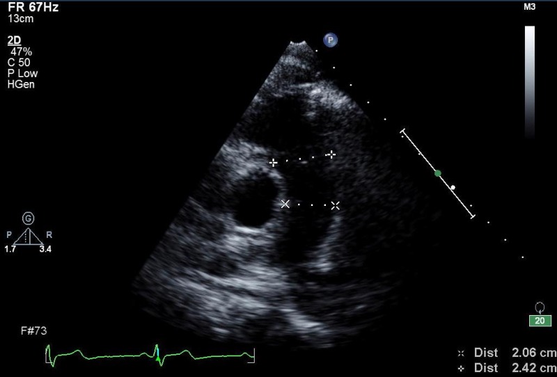
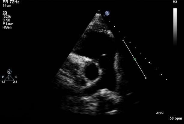
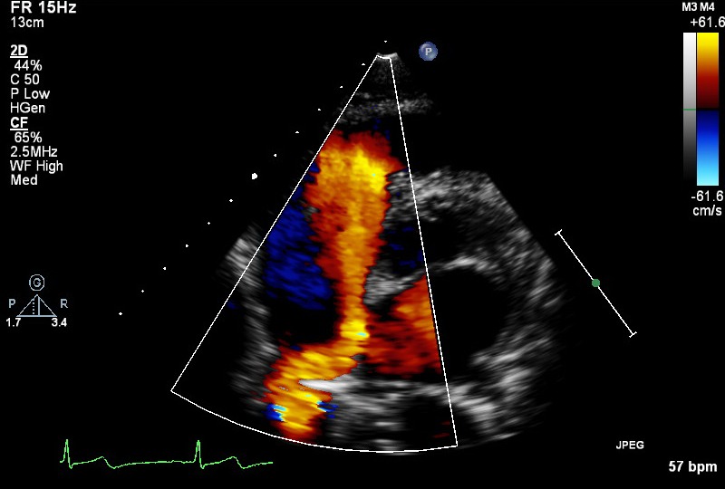
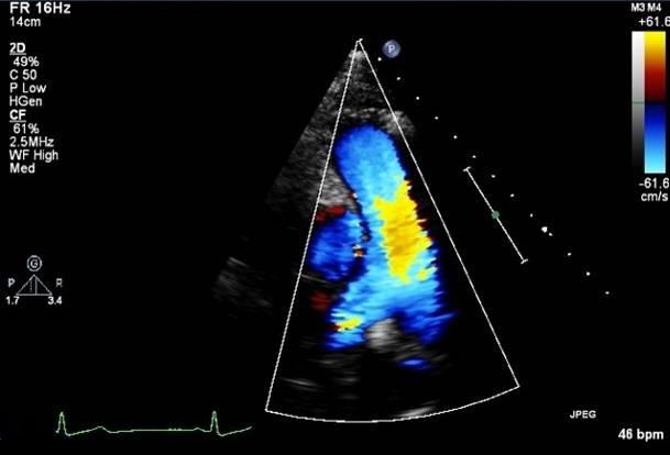
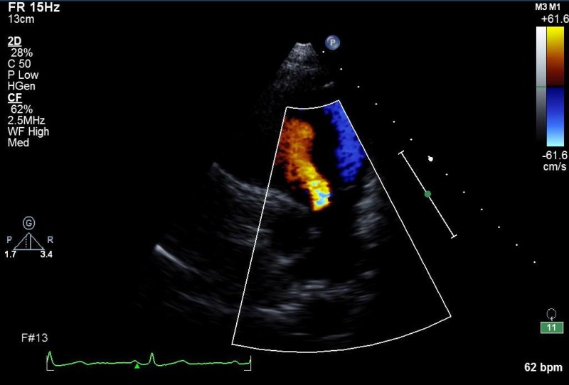
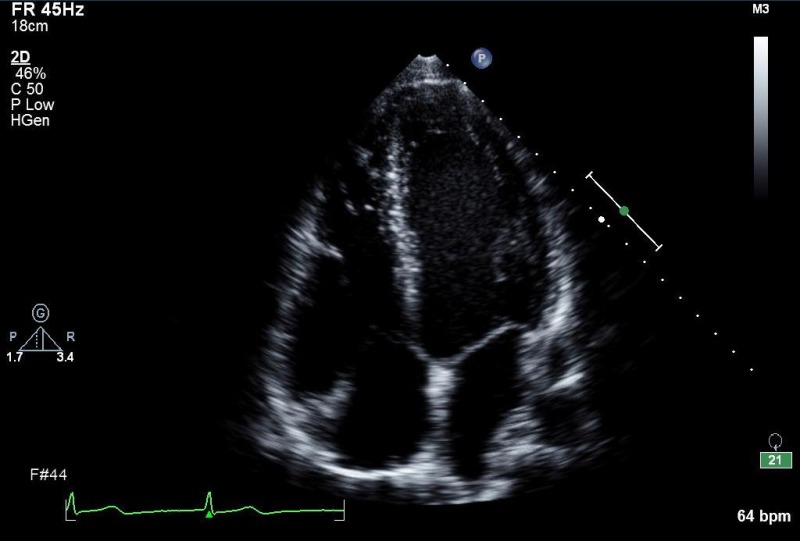
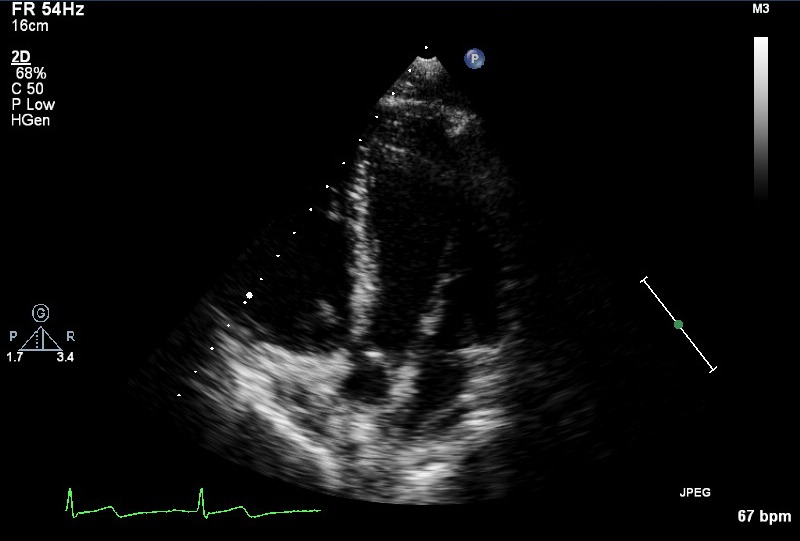
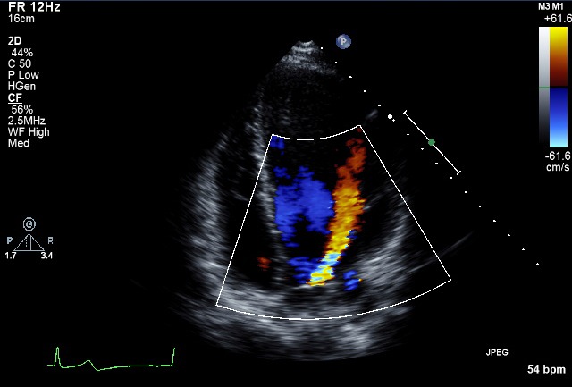
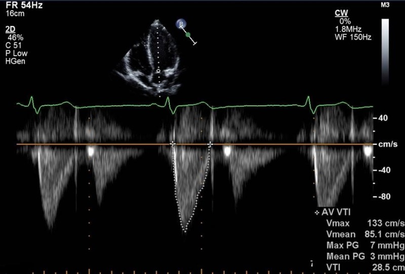
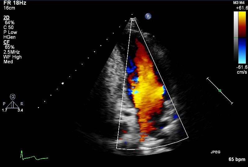
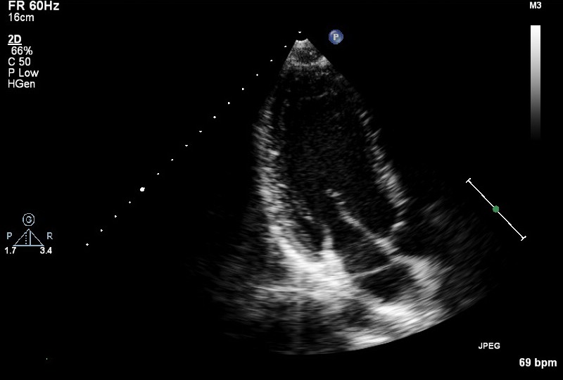
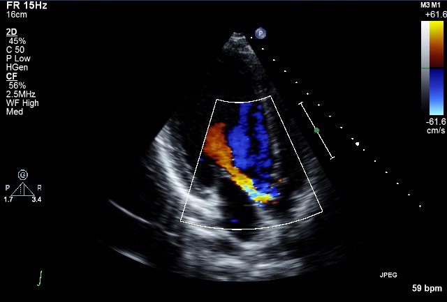
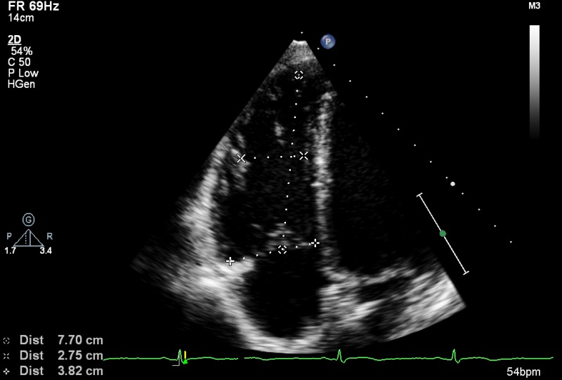
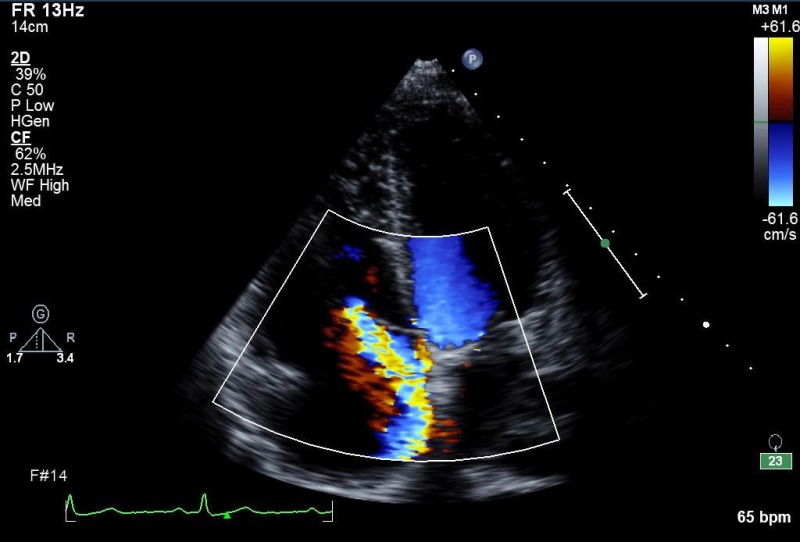
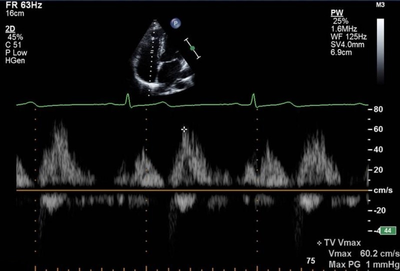
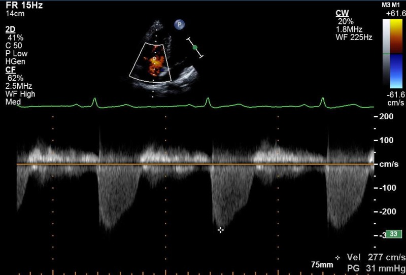
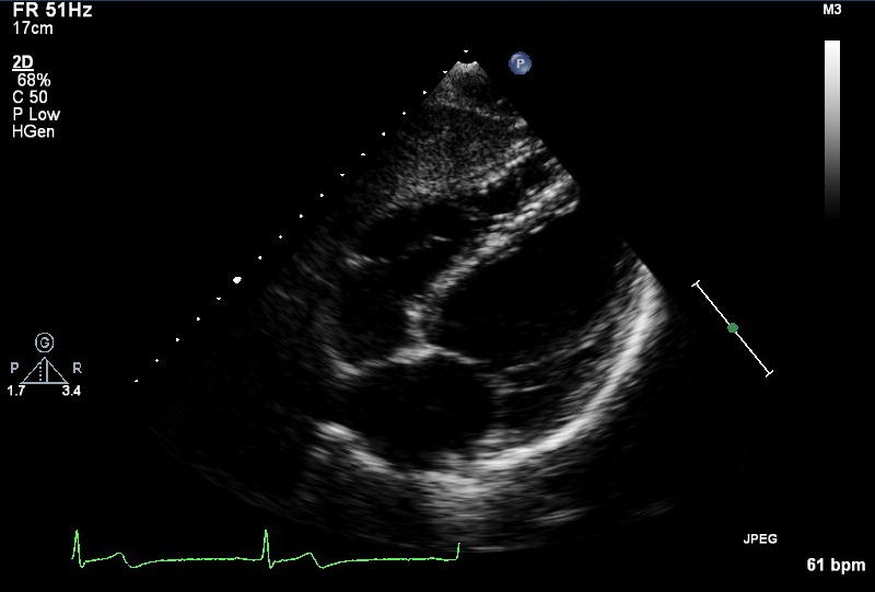
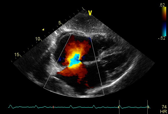
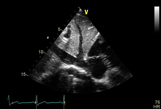
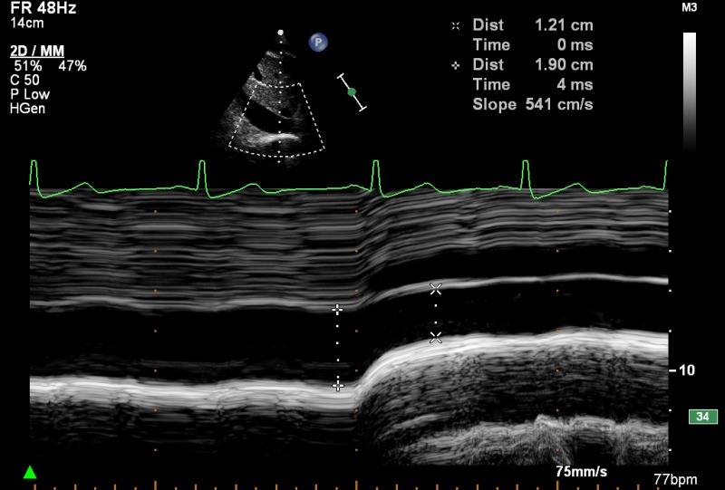
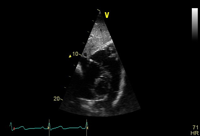
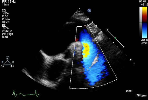
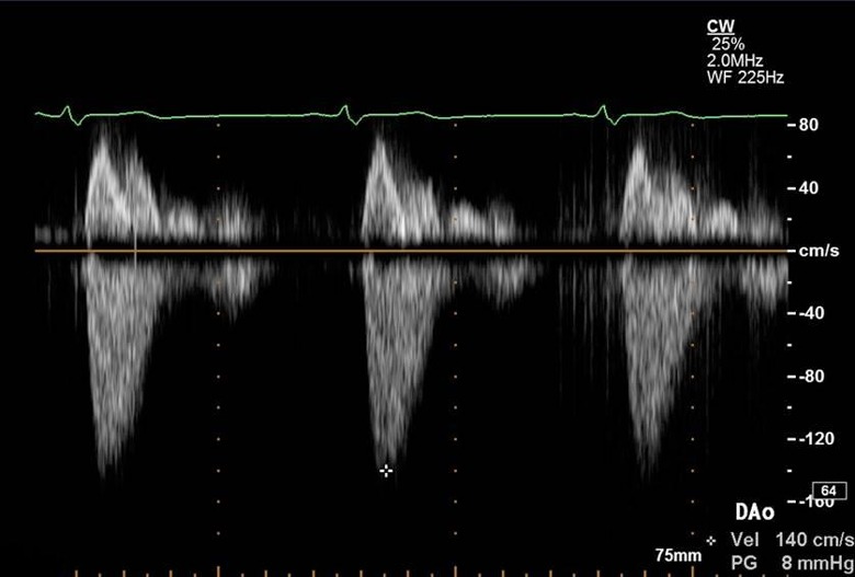
The layout has been altered to provide a visual example of the ideal image that should be acquired in each acoustic window. This is supported by text that follows a standard layout – the acoustic window and transducer position in the first column, followed by the modality to be used, measurements to be made at that location and an explanation if additional information is deemed necessary.
A standard adult transthoracic echocardiogram
1. Benefits and general principles
A standardised approach to performing an echocardiogram is extremely important not only to ensure that pathology is not missed but to facilitate comparison between studies.
1.1. The intended benefits of this Guideline are:
To support cardiologists and echocardiographers to develop local protocols and quality control programmes for an adult transthoracic study. These minimum requirements and recommendations provide a template against which studies in any department should be audited.
To promote quality by defining a 'minimum dataset' of descriptive terms and measurements.
To promote quality by defining a recommended dataset of descriptive terms and measurements that departments should work toward obtaining in all studies.
To facilitate accurate comparison of serial echocardiograms performed in patients at the same or different sites.
To facilitate the transition to digital echocardiography acquisition and reporting systems that use database (software) architecture.
1.2. There is broad agreement regarding the standard views and recordings essential in an echocardiographic examination. There is, however, no evidence-base and these recommendations and requirements represent a consensus view on the components of a complete TTE study.
1.3. It is expected that a standard echocardiogram following at least these minimum requirements will be performed in all adults when an echocardiogram is requested. This type of study is expected to make up the majority of those performed within any department, whether in the community or in hospital.
It is recognised that focused studies may be appropriate in some circumstances agreed locally. Focused TTE can either mean focusing on major abnormalities predominantly in an urgent clinical situation, e.g. pericardial effusion, or focusing on a particular aspect of the heart, e.g. longitudinal monitoring of left ventricular function. The skill level required for such studies is very high and it is expected that the patient will previously have had a full-standard TTE before monitoring commences or after an emergency assessment has been completed. Such studies should be clearly identified as focused studies and are not covered by this Guideline.
1.4. When the condition or acoustic windows of the patient prevent the acquisition of one or more components of the minimum dataset, or when measurements result in misleading information (e.g. off-axis measurements) this should be stated.
It is recommended that any study is accompanied by a statement regarding the image quality achieved: good/fair/poor.
1.5. Unless the physical condition of the patient prevents transfer, all TTEs should be performed in a suitable environment, with optimal facilities to obtain the highest quality ultrasound images, including lighting, space and imaging couches, whilst guaranteeing patient privacy. These facilities demand – except in exceptional circumstances – that echocardiography is delivered in an appropriately equipped department that satisfies the requirements of the BSE Departmental Accreditation process. This ensures optimum conditions for a detailed study, reduces the risk of musculoskeletal disorders for echocardiographers (http://www.hse.gov.uk/healthservices/management-of-musculoskeletal-disorders-in-sonography-work.pdf), and may reduce the risk of hospital-acquired infection. When portable echocardiography has to be performed at the bedside, the requirements of the minimum dataset must be met.
2. Identifying information
The images acquired should be clearly labelled with patient identifiers, including the following:
Patient name.
A second unique identifier such as hospital number or date of birth.
Identification of the operator, e.g. initials.
3. Electocardiogram (ECG)
An ECG should be attached ensuring good tracings to facilitate the acquisition of complete digital loops. Loops should be examined and adjusted accordingly in order to ensure a clear representation of the image acquired.
4. Height/weight/haemodynamic variables
Qualitative and quantitative evaluation of chamber size and function is a major component of every echocardiographic examination. Chamber dimensions may be influenced by age, gender and body size. Therefore, consideration should be given to the use of referenced ranges indexed to height or body surface area. In addition, velocities measured using Doppler should take account of pulse rate and blood pressure. No recommendation is made to the routine use of indexed measurements, but facilities should be available to sonographers to measure height, weight, pulse rate and blood pressure at the time of an echocardiogram.
5. Duration
The average time required for performance and reporting of a fully comprehensive TTE following these recommendations is considered to be 40–45 min, although it is understood that some studies may take longer whilst others may take less time. The time taken for a standard TTE should include time to complete a report, and should also take into account the time taken for patient preparation.
6. Report
No standard TTE is complete until a report is released and is made available to the referring individual. The majority of studies performed in a department should be reported immediately on completion and a report available on discharge of a patient from the echocardiography facility.
It is recognised that there are times when a review of images and further consideration is required, for example when the individual performing the scan does not hold proficiency accreditation and the scan requires review before release, although this should be done as soon as possible.
7. Chaperones
A standard TTE is not considered as an intimate examination, but performance still requires patient sensitivity. Chaperones should not usually be required for standard TTE; however, for all TTE studies, patients should be offered a gown.
Echocardiography departments should send out an information leaflet with any appointment. This should include a statement that a relative or friend could accompany the patient to act as a chaperone during the study if preferred. If a friend or relative cannot attend, the leaflet should include an offer to provide a chaperone if requested by the patient. This leaflet should either offer a chaperone by mutual arrangement or, if facilities and personnel allow, a chaperone to be provided on request when the patient arrives.
A notice should be displayed in the Echocardiography department where it can be seen by patients repeating the offer of a chaperone if requested. In practice, it is expected that the majority of patients would not need or have a chaperone.
The minimum dataset
The minimum dataset and recommended sequence for a standard TTE is shown in Table 1. The minimum requirements are depicted in bold text and recommendations in italics. The minimum requirements are also summarised in Appendix 1.
Table 1.
Minimum dataset for transthoracic echocardiography. Minimum requirements are depicted in bold text and identify the views and measurements that should be performed in all subjects being scanned for the first time provided that they can be obtained reliably. However wherever possible a comprehensive study should be performed. Recommendations are depicted in italics and together with the minimum requirements form the basis of a comprehensive examination
| View (modality) | Measurement | Explanatory note | Image |
|---|---|---|---|
| PLAX (2D) |
LVIDd/s, IVSd, LVPWd (either 2D or M mode measurement)
LA size (end ventricular systole) (either 2D or M mode measurement) |
LV cavity size, wall thickness, radial function
LA appearance MV leaflet and annulus appearance and function: thickness, mobility, calcification, commissural fusion, sub-valve apparatus |
|
| PLAX (2D) | AV/LVOT appearance and function |
|
|
| PLAX (2D) | Proximal RVOTd |
|
|
| PLAX (2D) |
Sinus of Valsalva (either 2D or M mode measurement, inner edge to inner edge at widest diameter)
Annulus, ST junction, proximal ascending aorta (inner edge to inner edge, at widest diameter) |
Aortic root – appearance and function |
|
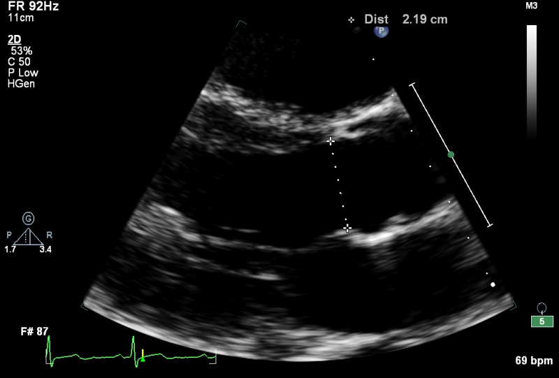
| PLAX (2D) | LVOT for AV area/SVol in mid systole | Approximately same location as the PW sample volume in the A5C view (measured in the LVOT up to 1 cm from the annulus) |
|
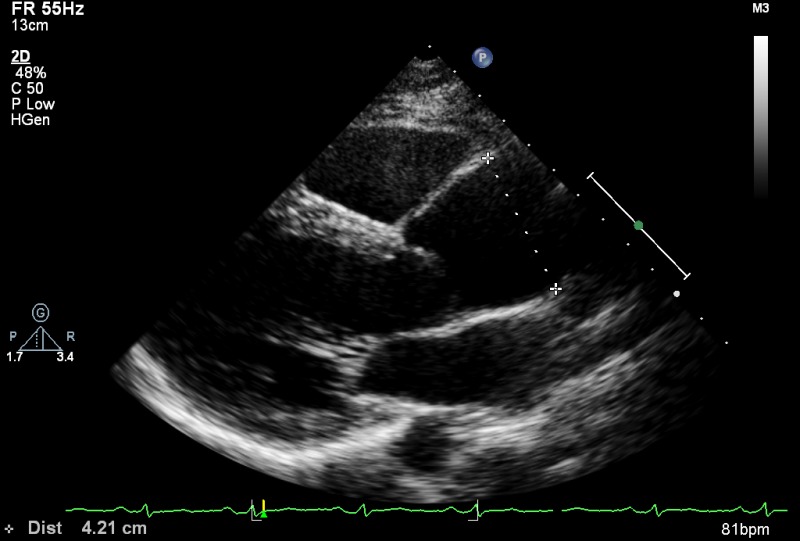
| PLAX (2D) | Proximal ascending aorta at widest diameter (inner edge to inner edge) | Tilted superiorly to demonstrate mid ascending aorta |
|
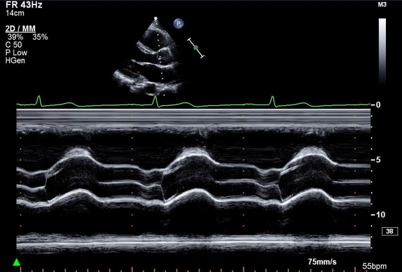
| PLAX (MM) |
Aortic root (end diastole)
Maximum LA size (end systole), providing 2D image is on axis |
Aortic valve at leaflet tips |
|
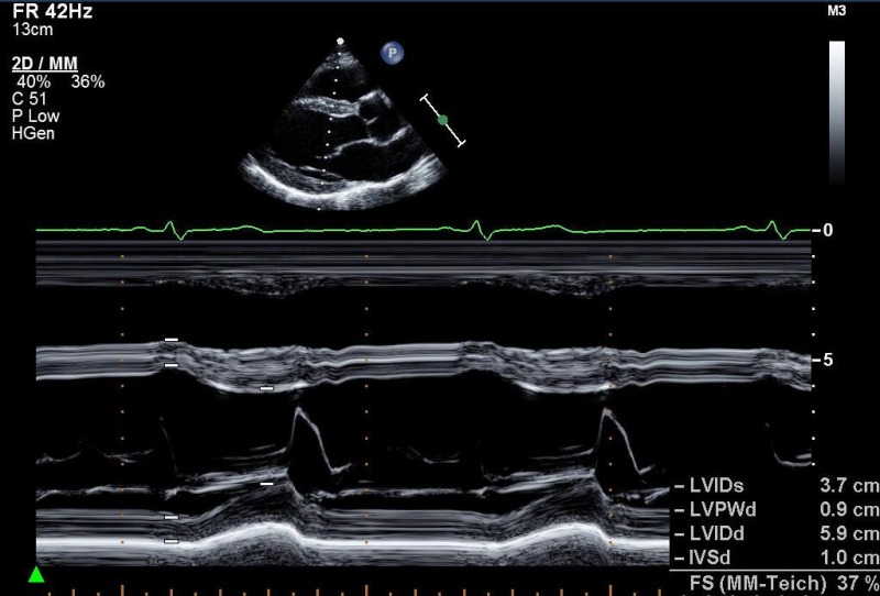
| PLAX (MM) | LVIDd/s, IVSd, LVPWd (either/or 2D measurement) | Left ventricle, just distal to MV leaflet tips |
|
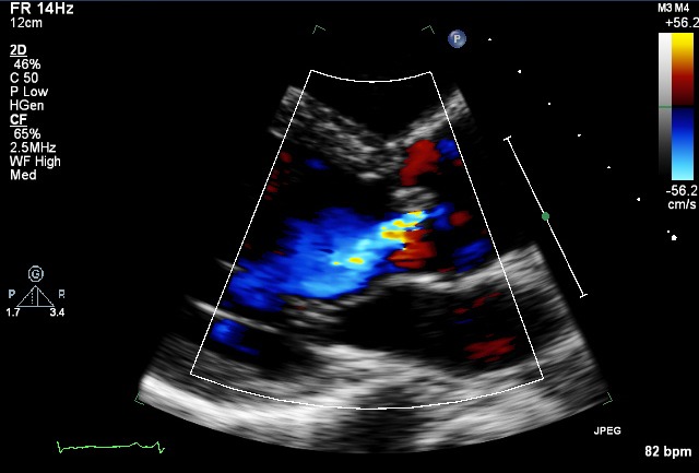
| PLAX (CFM) |
Look for abnormal colour flow
Adjust Nyquist limit: 50–60 cm/s |
|
|
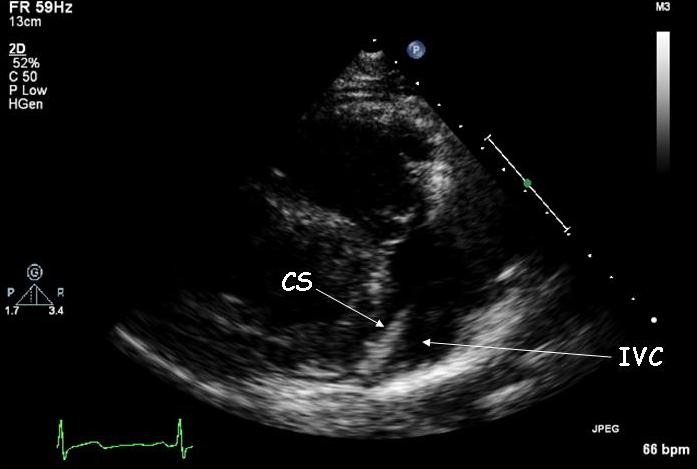
| PLAX RV inflow (2D) |
RV cavity size and function
RA, IVC, +/− coronary sinus TV – appearance and function |
|
|
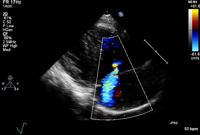
| PLAX RV inflow (CFM) | TV inflow, TR |
|
|
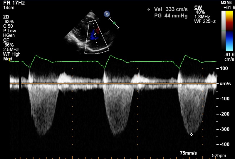
| PLAX RV inflow (CW) | TR V max | If good alignment with jet |
|
| PLAX RV outflow (2D) | Distal RVOT | RVOT, PV, main PA, LPA |
|
| PLAX RV outflow (CFM) |
RVOT, PA, PS, PR
Optional to PSAX |
|
|
| PLAX RV outflow (PW) | Optional to PSAX | ||
| PLAX RV outflow (CW) | Optional to PSAX | ||
| PSAX outflow (2D) | Proximal RVOT diameter |
RVOT (function)
AV – appearance and function LA/atrial septum TV – appearance and function |
|
| PSAX outflow (2D) | PV annulus, main PA | PV, main PA |
|
| PSAX outflow (2D) | Proximal branch PA's |
|
|
| PSAX outflow (CFM) |
Ao/LA
Atrial septum IVC TV inflow, TR |
|
|
| PSAX outflow (CFM) | PA, look for abnormal colour flow |
|
|
| PSAX outflow (CFM) | RVOT (PR) |
|
|
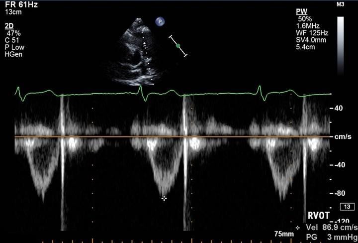
| PSAX outflow (PW) | V max , V mean , VTI | RVOT (just proximal to PV) |
|
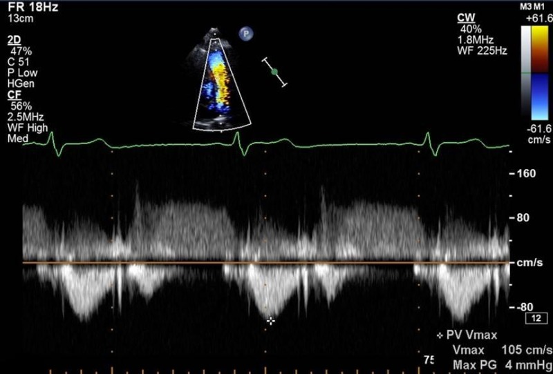
| PSAX outflow (CW) | V max , V mean PHT |
PA
PR density and contour of signal |
|
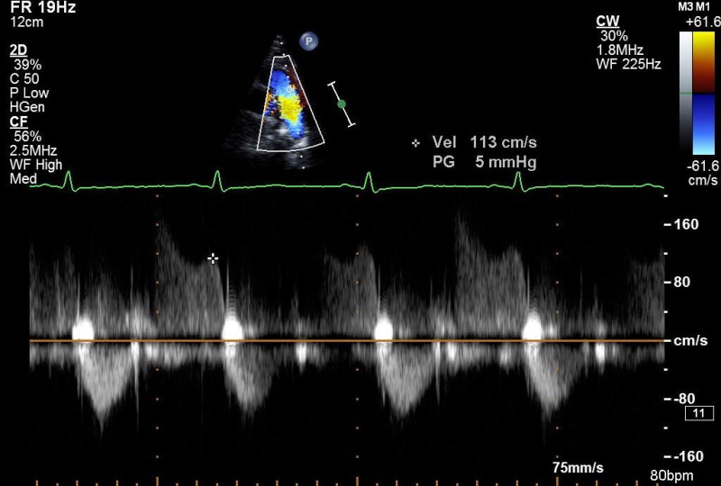
| PSAX outflow (CW) | PR V max (end diastolic PA pressure) | End diastole |
|
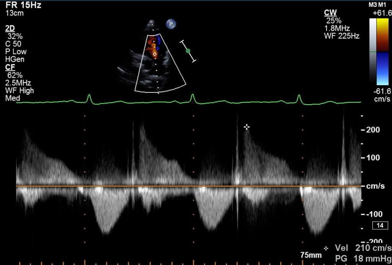
| PSAX outflow (CW) | PR V max (mean diastolic PA pressure | Early diastole |
|
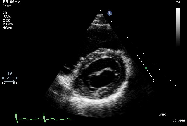
| PSAX Base (2D) |
MV leaflet and annulus:
– appearance and function – thickness, mobility, calcification, commissural fusion, sub-valve apparatus |
|
|
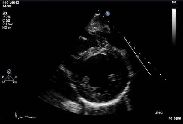
| PSAX mid (2D) |
Sweep beam from base to apex
Radial systolic function/regional wall motion abnormalities Integrity of ventricular septum |
|
|
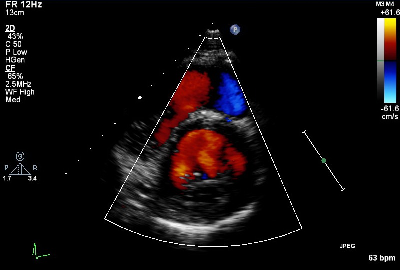
| PSAX (CFM) |
Sweep beam from base to apex
Integrity of ventricular septum |
|
|
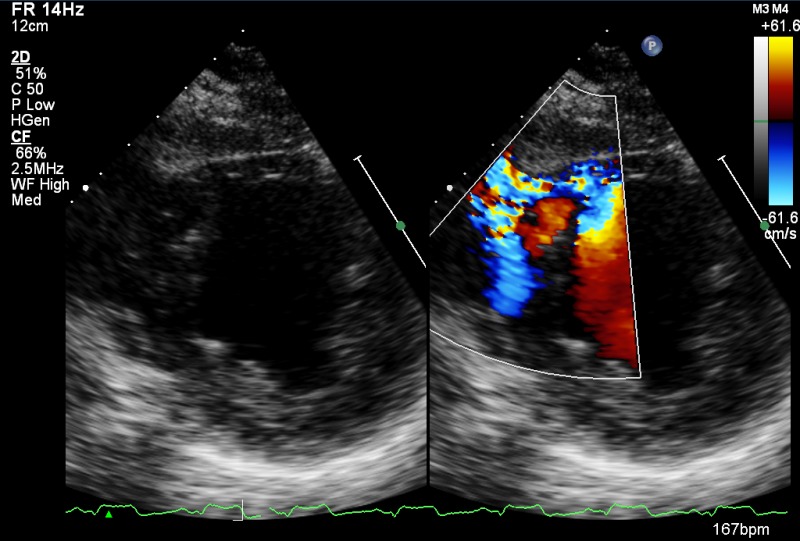
| PSAX (CFM) | VSD's (congenital/post infarct) |
|
|
| A4C (2D) |
LV cavity size, wall thickness (Inferoseptum, anterolateral)
Longitudinal and radial function: RWMA's (inferoseptal and anterolateral) MV/TV appearance and function Atrial septal mobility |
|
|
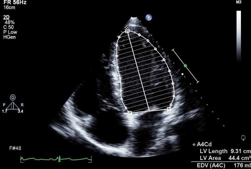
| A4C (2D) | Area/volume (should not be done if images sub optimal) |
LV end diastolic area/volume (BSA indexed). Consider 3D volumes, unless images are suboptimal
Consider LV opacification contrast if poor image quality |
|
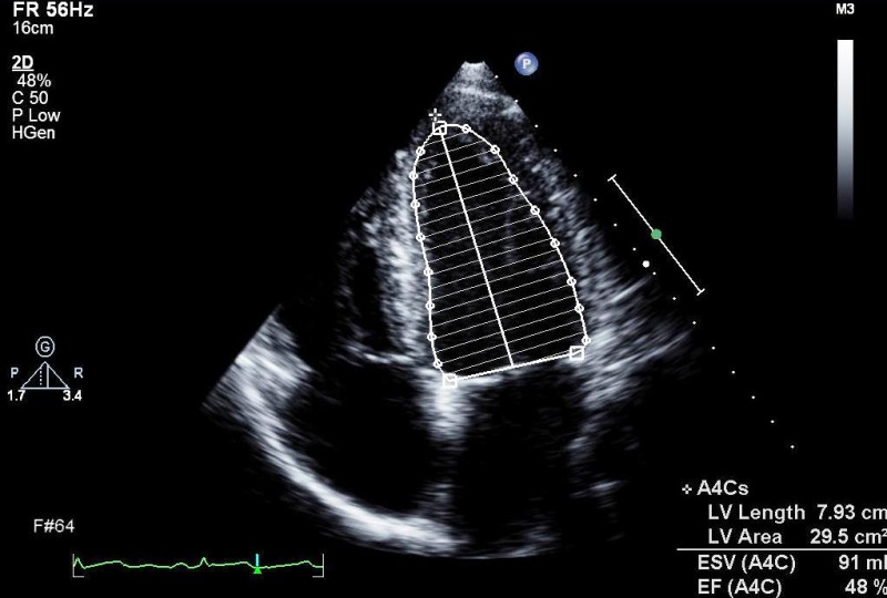
| A4C (2D) |
LV end systolic area/volume (BSA indexed).
Consider 3D volumes, unless images are suboptimal
Consider LV opacification contrast if poor image quality |
|
|
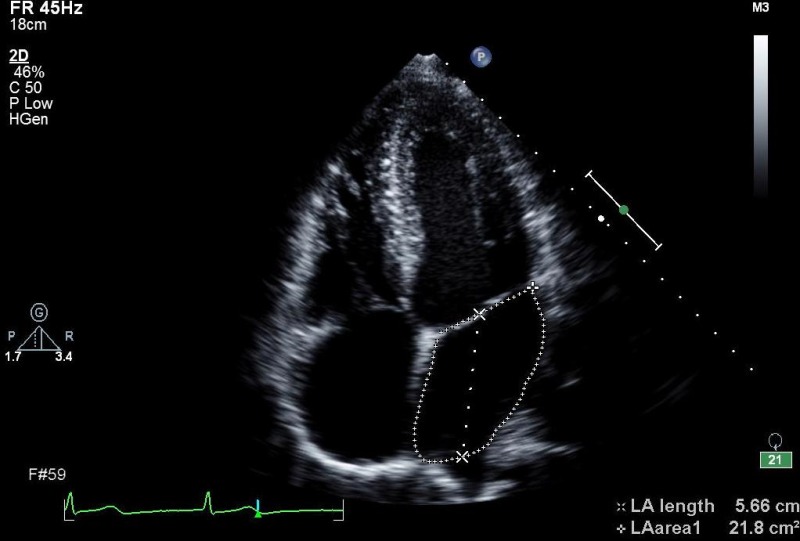
| A4C (2D) | LA volume | LA size (measured at end ventricular systole and BSA indexed) |
|
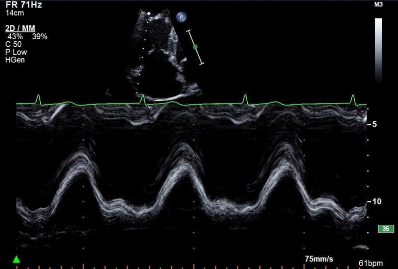
| A4C (MM) |
TAPSE
MAPSE |
TV annulus
MV annulus |
|
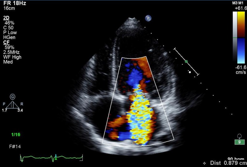
| A4C (CFM) | MV inflow, look for abnormal flow |
|
|
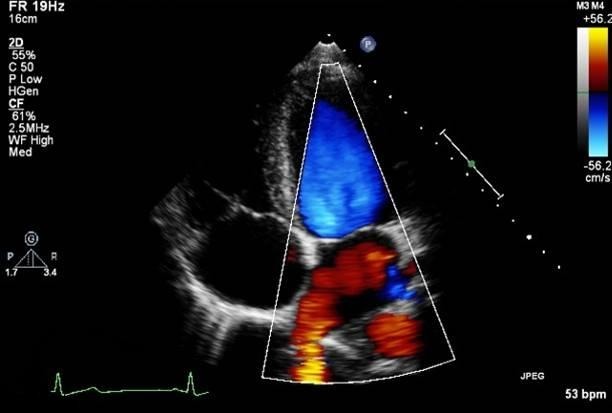
| A4C (CFM) |
RLPV either/or RUPV
LUPV, LLPV can also be imaged |
|
|
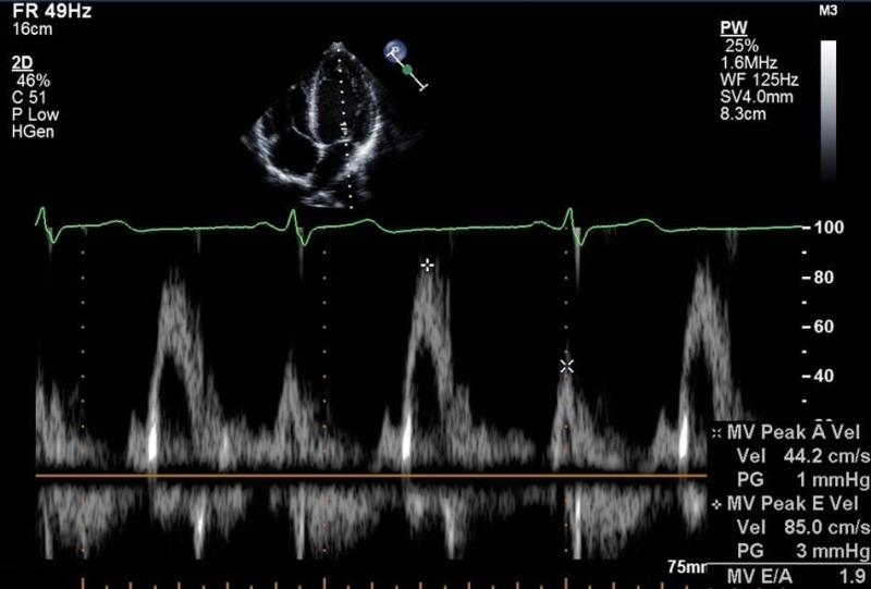
| A4C (PW) | E V max , A V max | LV inflow (MV tips) |
|
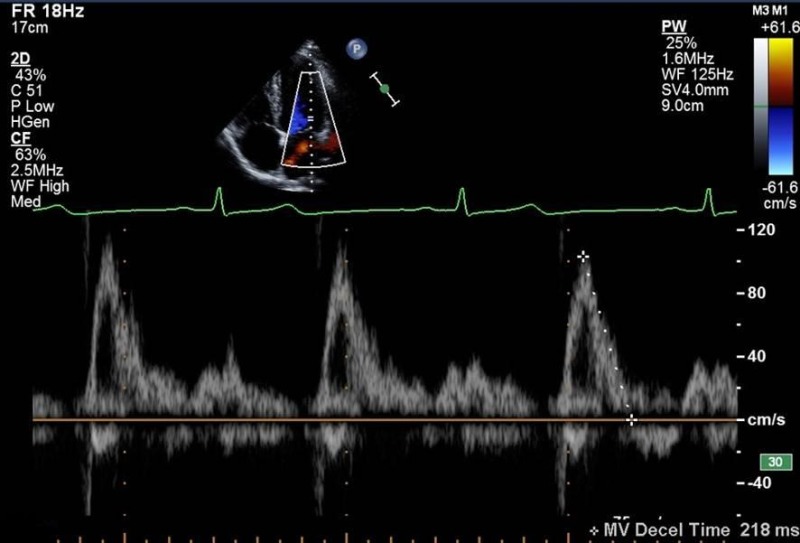
| A4C (PW) | Deceleration time |
|
|
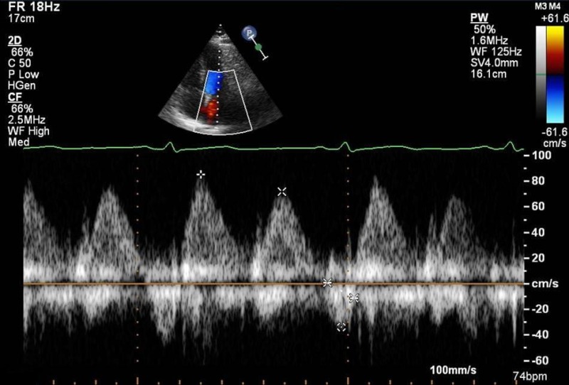
| A4C (PW) |
PV
S
/PV
D
PVa a dur −A dur |
Right lower pulmonary vein |
|
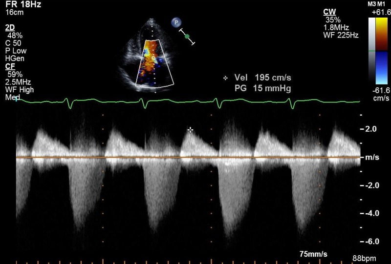
| A4C (CW) | MR (shape and density of signal) |
|
|
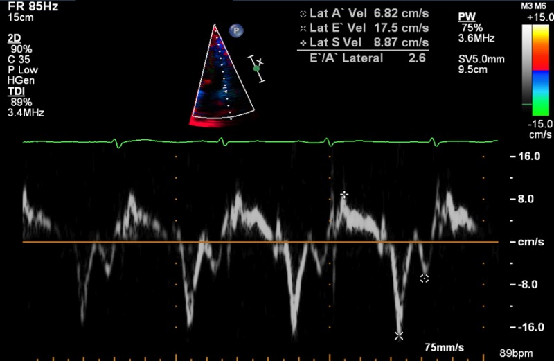
| A4C (TDI) |
e'
a', s' |
Septal and/or lateral LV
Lateral RV |
|
| A5C (2D) |
LV cavity size, wall thickness, function
LVOT AV appearance and function |
|
|
| A5C (CFM) | LVOT, look for abnormal colour flow |
|
|
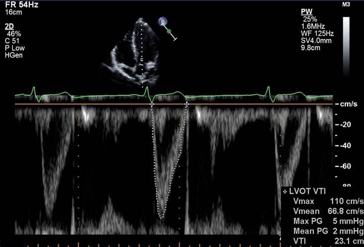
| A5C (PW) |
V
max
VTI (stroke volume, cardiac output) |
LVOT |
|
| A5C (CW) |
|
||
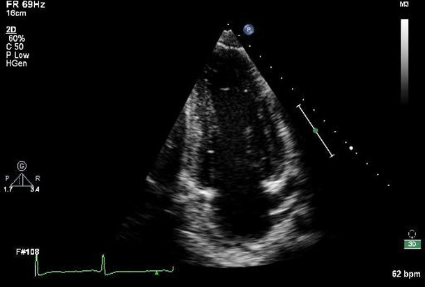
| A2C (2D) | LV cavity size, wall thickness: function (anterior, inferior) |
|
|
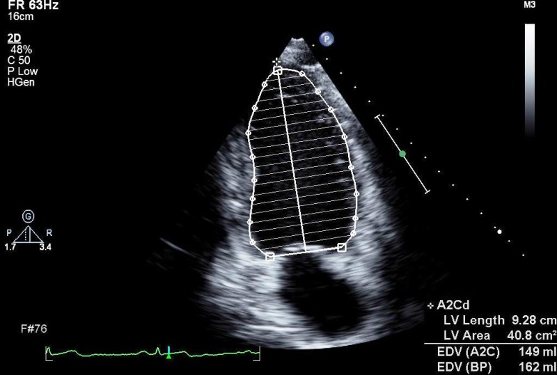
| A2C (2D) | LV area/volume |
LV end diastolic area/volume
Consider 3D volumes, unless images are suboptimal Consider LV opacification contrast if poor image quality |
|
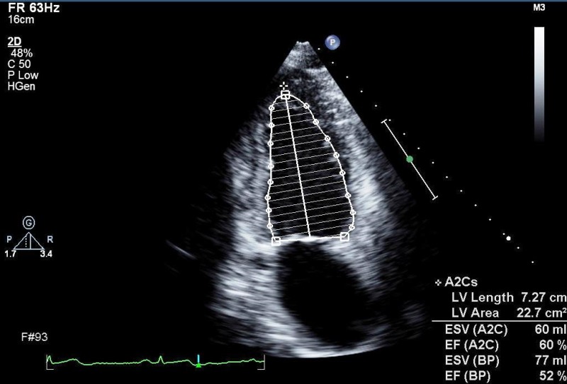
| A2C (2D) |
LV end systolic area/volume
Consider 3D volumes, unless images are suboptimal Consider LV opacification contrast if poor image quality |
|
|
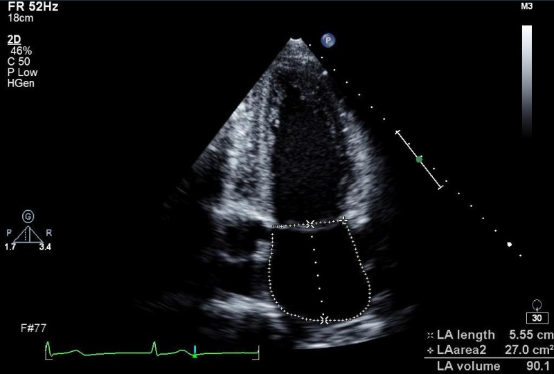
| A2C (2D) |
LA area/volume (measure at end ventricular systole)
Modified Simpsons or area length method |
LA size |
|
| A2C (CFM) | LV inflow, look for abnormal colour flow |
|
|
| A2C (PW) | E, A, DT if not reliable from A4C | LV inflow (MV tips) | |
| A2C (CW) | V max , V mean if not reliable from A4C | ||
| A3C (2D) |
LV cavity size, wall thickness:
function (anteroseptal and inferolateral) AV/LVOT appearance and function |
|
|
| A3C (CFM) | LVOT, LV inflow, look for abnormal colour flow |
|
|
| ALAX (PW) | E, A, DT,VTI if not reliable from A5C |
LV inflow (MV tips)
LVOT |
|
| A3C (CW) |
V
max
, V
mean
V max , V mean |
LV inflow
LVOT |
|
| Modified A4C (2D) |
RVID base (d)
Mid RV diameter RV length (base to apex) RA area |
RV cavity size and function
RA size |
|
| Modified A4C (CFM) | TV inflow, TR |
|
|
| Modified A4C (PW) | E V max | RV inflow (TV leaflet tips) |
|
| Modified A4C (CW) | V max (RV systolic pressure, PAP) | TR |
|
| SC4C (2D) | Four chamber structures, atrial septum |
|
|
| SC4C (CFM) |
Atrial septum
Consider reducing Nyquist limit to detect low velocity flow |
|
|
| SCSAX (2D) | IVC, hepatic vein (modified view) |
|
|
| SCSAX (MM) | Size and respiratory variation (‘sniff’) | IVC just proximal to hepatic vein |
|
| SCSAX (2D) |
SAX structures
Atrial septum, TV, RVOT, PV, PA's |
|
|
| SCSAX (2D) | Abdominal aorta (modified view) |
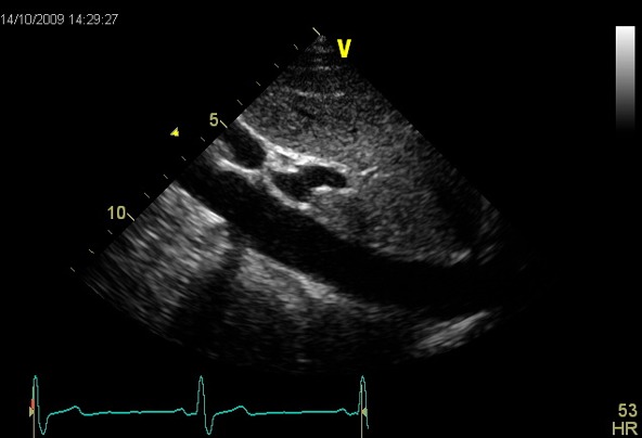
|
|
| SCSAX (PW) | Hepatic veins |
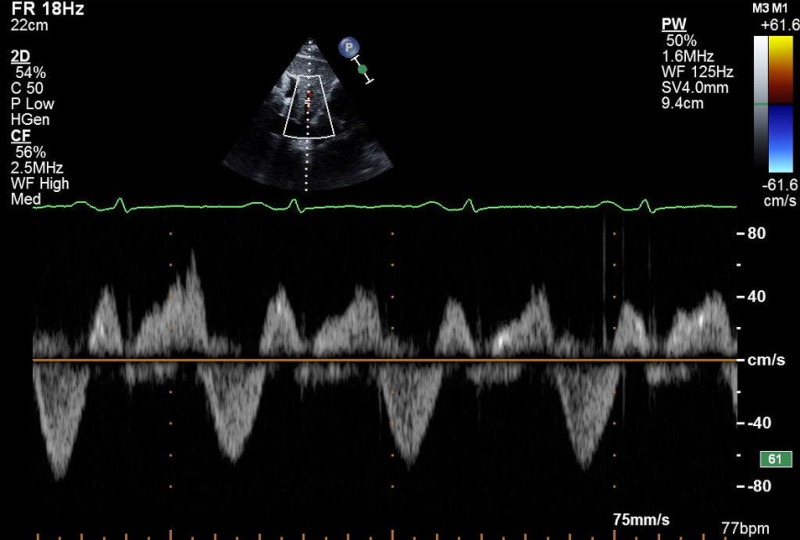
|
|
| SCSAX (PW) | Abdominal aorta |
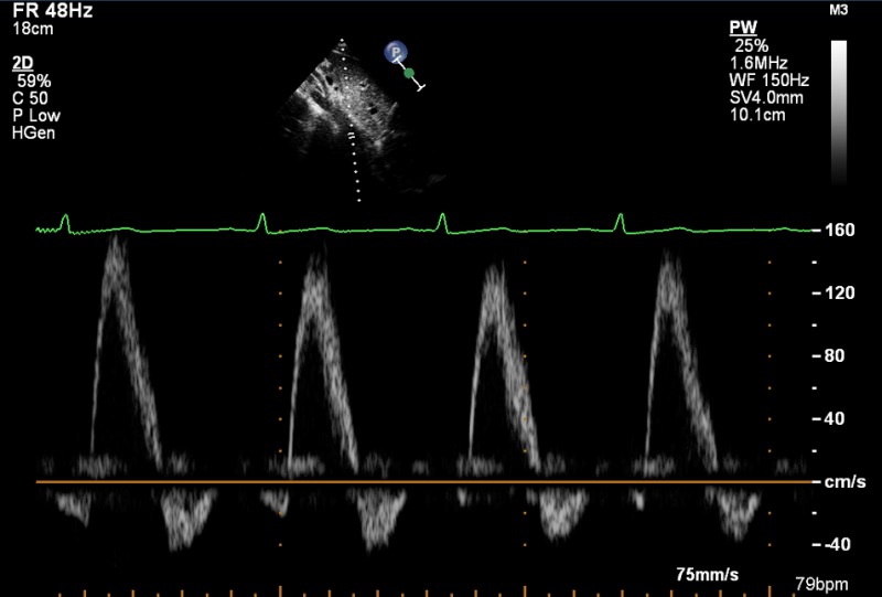
|
|
| SSN (2D) | Arch |
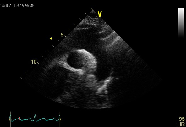
|
|
| SSN (CFM) | Arch, RPA, look for abnormal colour flow |
|
|
| SSN (CW) | V max |
Descending aorta with imaging probe, if good alignment with jet
Descending aorta with non imaging probe, if poor jet alignment with imaging probe |
|
Appendix 1.
Minimum dataset measurements
| 1. Views to be obtained: | |
| PLAX | Parasternal long axis |
| PLAX | Tilted RV inflow |
| PSAX | Parasternal short axis: base, mid, apex |
| A4C | Apical four chamber |
| Modified A4C for RV | |
| A2C | Apical two chamber |
| A5C | Apical five chamber |
| SC | Subcostal |
| SSN | Suprasternal |
| 2. Recorded and measured where appropriate | |
| LVIDd/s | Left ventricular internal dimension in diastole and systole |
| IVSd | Interventricular septal width in diastole |
| LVPWd | Left ventricular posterior wall width in diastole |
| LA | Left atrial dimension in PLAX |
| Sinus | Sinus of valsalva |
| TR Vmax | Tricuspid regurgitation maximal velocity |
| LVEDvol d/s | Left ventricular end-diastolic and systolic volume (biplane/3D) |
| LVEF | Left ventricular ejection fraction |
| LA volume | Left atrial volume at end-ventricular systole (area-length/biplane) |
| TAPSE | Tricuspid annular plane systolic excursion |
| Mitral E/A | Mitral valve maximal velocity early and atrial filling |
| e' | Lateral and/or septal early myocardial relaxation velocity |
| AV Vmax | Maximal aortic velocity on CW |
| RV base | Right ventricular basal dimension in diastole |
| IVC dimension | Estimation of RA pressure |
Abbreviations
| Views | |
| A2C | Apical two chamber |
| A4C | Apical four chamber |
| A5C | Apical five chamber |
| A3C | Apical long axis or apical three chamber |
| PLAX | Parasternal long axis |
| PSAX | Parasternal short axis |
| SC | Subcostal |
| SSN | Suprasternal |
| Modality | |
| CFM | Colour flow Doppler |
| CW | Continuous wave Doppler |
| PW | Pulse wave Doppler |
| TDI | Tissue Doppler imaging |
| Measurement and explanatory text | |
| Ao | Aorta |
| AV | Aortic valve |
| BSA | Body surface area |
| DT | Deceleration time |
| IVC | Inferior vena cava |
| IVSd | Interventricular septal width in diastole |
| LA | Left atrium |
| LLPV | Left lower pulmonary vein |
| LPA | Left pulmonary artery |
| LUPV | Left upper pulmonary vein |
| LV | Left ventricle |
| LVIDd/s | Left ventricular internal dimension in diastole and systole |
| LVOT | Left ventricular outflow tract |
| LVPWd | Left ventricular posterior wall width in diastole |
| MAPSE | Mitral annular plane systolic excursion |
| MV | Mitral valve |
| PA | Pulmonary artery |
| PAP | Pulmonary artery pressure |
| PHT | Pressure half-time |
| PR | Pulmonary regurgitation |
| PS | Pulmonary stenosis |
| PV | Pulmonary valve |
| RA | Right atrium |
| RLPV | Right lower pulmonary vein |
| RUPV | Right upper pulmonary vein |
| RV | Right ventricle |
| RVIDd | Right ventricular cavity diameter in diastole |
| RWMA | Regional wall motion abnormality |
| RVOT | Right ventricular outflow tract |
| RVOTd | Right ventricular outflow tract dimension |
| STJ | Sinotubular junction |
| SVol | Stroke volume |
| TAPSE | Tricuspid annular plane systolic excursion |
| TR | Tricuspid regurgitation |
| TV | Tricuspid valve |
| Vmax | Maximum velocity |
| VSD | Ventricular septal defect |
| VTI | Velocity time integral |
Abbreviations
Footnotes
(G Wharton is the lead author)
(R Steeds is the Guidelines Chair)
Declaration of interest
The authors declare that there is no conflict of interest that could be perceived as prejudicing the impartiality of this guideline.
Funding
This guideline did not receive any specific grant from any funding agency in the public, commercial or not-for-profit sector.


 This work is licensed under a