Abstract
In this paper we demonstrate the enhancement of the sensing capabilities of glass capillaries. We exploit their properties as optical and acoustic waveguides to transform them potentially into high resolution minimally invasive endoscopic devices. We show two possible applications of silica capillary waveguides demonstrating fluorescence and optical-resolution photoacoustic imaging using a single 330 μm-thick silica capillary. A nanosecond pulsed laser is focused and scanned in front of a capillary by digital phase conjugation through the silica annular ring of the capillary, used as an optical waveguide. We demonstrate optical-resolution photoacoustic images of a 30 μm-thick nylon thread using the water-filled core of the same capillary as an acoustic waveguide, resulting in a fully passive endoscopic device. Moreover, fluorescence images of 1.5 μm beads are obtained collecting the fluorescence signal through the optical waveguide. This kind of silica-capillary waveguide together with wavefront shaping techniques such as digital phase conjugation, paves the way to minimally invasive multi-modal endoscopy.
OCIS codes: (060.2350) Fiber optics imaging, (090.1995) Digital holography, (070.5040) Phase conjugation, (170.2150) Endoscopic imaging
1. Introduction
Glass capillaries, referred to as capillary waveguides (CWGs) in the photonics community due to their ability to support the propagation of waveguiding modes in the annular glass ring, have been consistently exploited by researchers as sensors [1] or as biosensors in lab on a chip platforms [2]. Nevertheless no application was demonstrated showing their use as an imaging device per se. Although optical fibers are widely used in endoscopy, at first glance the use of a CWG for endoscopic purposes does not bring advantages. In reality however, the presence of a physical access to the sample side, enabled by the presence of the hollow core at the center, adds a degree of freedom to the endoscopic device, which can be used for many applications. For example an endoscopic device can be used to deliver high-energy light for ablation purposes, so the hollow core could be used for eliminating gases formed during the ablation process. Alternatively, an endoscope based on CWGs can be used to check in vivo the effect of drugs that can be injected using the same device.
Usually endoscopes are made out of bundles of single mode fibers, or one single mode fiber equipped with a micro-fabricated lens and a scanning system to steer the laser beam [3,4]. One problem carried by a direct transition from single-mode fibers to CWGs is that lateral dimension of the endoscopic device would increase. Fiber bundles and single-mode fiber endoscopes usually have large diameters (in the millimeter range): adding a hollow core in each optical fiber would not improve this aspect. Moreover, the point spread function of the imaging system would change from a quasi-Gaussian beam (the fundamental mode of a single-mode fiber) to a donut-like beam (the fundamental mode of a CWG), implying a deconvolution step while doing imaging.
Recently it has been shown that is possible to obtain ultrathin endoscopes using multimode fibers (MMFs). Dynamically shaping light using a spatial light modulator (SLM), it is possible to scan a focus spot at the distal end of the MMF and collect the optically generated signal through the same fiber. In this way using an ultrathin fiber (only few hundreds of micrometers), high-resolution fluorescence imaging has been shown in [5–8].
This approach can be adapted to ultrathin capillaries having a relatively thick silica wall, which can be used as multimode optical waveguides. The use of a SLM can turn a CWG into an imaging system, paving the way to new applications that would be otherwise impossible to achieve in conventional fiber based endoscopy.
In this paper we demonstrate two new possible applications: using digital phase conjugation (DPC [6]), a 330 μm-thick silica capillary can also be used as a fluorescence and optical resolution photoacoustic endoscope. We combine fluorescence endoscopy [3] with optical resolution photoacoustic microscopy, which measures optical absorption in biological bodies [9,10]. A double imaging modality, in fact, can allow the acquisition of additional information about the structural and molecular heterogeneities of interrogated biological samples [11].
Photoacoustic imaging is possible using a highly energetic nanosecond laser pulse, which, when absorbed by a sample, generates an acoustic wave due to thermoelastic expansion. The detection of the photoacoustic waves using an ultrasound (US) transducer enables the formation of an image. If the resolution is limited by the ability of focusing light in a diffraction limited volume, we can speak about optical-resolution photoacoustic microscopy (OR-PAM) [12,13]. When widefield light is used to illuminate the sample, the resolution is given by the maximum US detectable frequency and by the characteristics of the US transducer. In this case we have acoustic-resolution photoacoustic microscopy (AR-PAM), with transverse resolution ranging from hundreds of micrometers to millimeters [14,15].
OR-PAM images are obtained by scanning a diffraction limited focused spot which can be done deep in tissues using a fiber bundle optical endoscope [11,16] and detecting the sound with an external US transducer. Fully encapsulated AR-PAM endoscopes have been demonstrated by Yang et al [17,18] using a single mode fiber and an actuation system for the beam steering. Recently OR-PAM images have been acquired by the same group using a device with an outer diameter of 3.4 mm and a lateral resolution of 9.2 μm [19]. OR-PAM by using a MMF has been demonstrated by Papadopoulos et al in [20]. The photoacoustic signal was collected using an external US transducer placed next to the interrogated sample, forming the photoacoustic image. The frequency of the generated signal was larger than 10 MHz. Since the attenuation of US in tissue increases linearly with frequency (around 0.5 dB/cm/MHz [21],) the imaging depth using this approach is limited to a few millimeters [20].
The use of a CWG eliminates the need of an US transducer at the tip of the endoscope, reducing its lateral dimension. The water-filled CWG can be used as a acoustic waveguide and guide high frequency US waves [22].
The use of hollow core, together with wavefront shaping techniques such as DPC and the light guiding properties of the silica part of the CWG, show new possible applications for this kind of waveguides.
2. Materials and methods
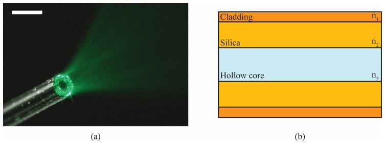
Figure 1 shows a picture of our CWG and a simplified schematic of its structure. The silica part of the capillary waveguide has a higher refractive index than the cladding and the hollow core (Fig. 1(b)). Therefore light undergoes total internal reflection at every interface of the CWG and can be guided [23]. The CWGs used in this work have an external diameter of only 330 μm. Surrounded by the 10 μm-thick cladding are the silica layer and the hollow core. The effective numerical aperture (NA) of the optical waveguides is 0.22, so using hollow core diameters of 100 μm and 150 μm, the silica part of the CWG behaves as a multimode optical waveguide, allowing focusing light by using DPC. The 100-μm and 150-μm inner diameter CWGs have approximately 5 × 10⁴ and 6 × 10⁴ optical guided modes, respectively. The water-filled core, which has a lower phase velocity compared to the silica, can be used as an acoustic waveguide to collect the US waves. Analogous to the case of light waveguiding in the silica part, this phase velocity contrast keeps the US wave confined inside the fluid core via total internal reflection at the fluid-solid interface [24]. In the frequency range observed in this work (10-30 MHz), the CWG with an internal diameter of 150 μm is a few mode waveguide. In particular, the first-order quasi-piston mode can propagate in the water-filled hollow core and exits the CWG as a quasi-spherical wave, which can be detected by a spherically focused US transducer [22].
Fig. 1.
Capillary waveguide (CWG): (a) Light escaping the CWG: a closer look to the silica annular part show the speckle diffraction pattern characteristic of multimode waveguides. Scale bar 500 μm; (b) Schematic of the side cross–sectional view of a CWG: the silica annular part of the CWG has a refractive index n2 higher than the cladding (n1) and the hollow core (n3, usually air or water), so light can be guided by total internal reflection. The hollow core adds a degree of freedom to this kind of waveguides respect to common optical fibers. The overall diameter of the CWG is 330 μm. The cladding is 10 μm-thick. The remaining part is composed of the silica part and the hollow core. In this work we used inner diameters of 150 μm (silica part 76.5 μm-thick) and 100 μm (silica part 106.5 μm-thick).
The basic experimental setup is shown in Fig. 2 . The output of a Q-switched Nd:YVO4 laser (wavelength of 532 nm, pulse width of 5 ns, repetition rate 200 Hz, output energy 300 μJ/pulse, NL-201, EKSPLA, Lithuania) is expanded and collimated using the lenses OBJ1 and L1. The polarizing beam splitter (PBS) splits the beam in two arms: the calibration arm goes to the CWG and the imaging arm is used as the reference beam to record the digital hologram for DPC. The former goes through a couple of galvomirrors (Cambridge Technology Inc., USA) and relayed through the unit-magnification 4f system L2-L3 (f = 10 cm) onto the back focal plane of the objective OBJ2. The pair of galvomirrors scans a focused spot in a regular grid in a plane at the distal end of the capillary (the sample side). On the other side of the capillary (the proximal side) the light coupled into the propagation modes of the capillary for each position of the focus, generates a speckle pattern. The amplitude and phase of this speckle pattern is digitally recorded with a CMOS detector (MV1-D1312IE-100-G2-12, Photonfocus, Switzerland) using off-axis digital holography [6]. The half-wave plate placed before the PBS controls the power ratio between the imaging and calibration arms. A delay line on the imaging arm is added in order to match the optical path length of the two arms and therefore to obtain the best interference fringe contrast. From each off-axis hologram, the phase of the speckle pattern can be digitally calculated on a personal computer. The conjugated distributions of the detected phases are assigned to the spatial light modulator (SLM - Pluto-VIS, Holoeye, Germany). The phase conjugated beams are sent back inside the waveguide, allowing the scanning of a focused spot on the sample side. During this operation, the calibration beam is blocked. The focus spot is formed again at the original position and it is imaged on the camera marked CCD in Fig. 2 through the 4f system OBJ2-L5 and the non-polarizing beam splitter BS1. The pulse energy at each phase conjugated spot is estimated around 500 nJ/pulse. It should be noted that after the calibration step, no optical element or transducer is needed on the sample side.
Fig. 2.
Experimental optical setup: The beam is expanded by the telescope formed by lenses OBJ1-L1 and is split in two arms by the polarizing beam splitter PBS: the calibration arm and the imaging arm. The calibration arm beam is focused on the capillary waveguide (CWG) by the objective OBJ2. The output of the capillary is imaged on the CMOS sensor through the 4f imaging system OBJ3-L4. The imaging arm, used as a reference beam, is combined with the image through the non-polarizing beam splitter BS2 generating a hologram. The phase conjugate beam is generated by displacing the calculated phase pattern on the SLM and the reference beam and is redirected back in CWG by BS2. The imaging system OBJ2-L5 and the beam splitter BS1 allow to check the generation of the phase conjugated focused spot on the CCD camera. The delay line and the half wave plates (λ/2) are used to optimize the quality of the digital hologram.
In the case of fluorescence imaging, the calibration objective OBJ2 is a 50 × long working distance (WD) objective (NA = 0.55, WD = 13 mm, Mitutoyo, Japan) and OBJ3 is a 20 × objective (NA = 0.42, WD = 20 mm, Mitutoyo, Japan). The light generated by the fluorescent sample is collected back through the silica ring of the CWG and detected by the CMOS camera. Two kinds of flexible fused silica capillaries are used to carry out the experiments: a polyimide coated (NA = 0.22, LTSP150375, Polymicro Technologies, USA) and a transparent Teflon coated (NA = 0.22, TSU100375, Polymicro Technologies, USA). The former has an inner diameter of 150 μm and silica guiding part of 76.5 μm; the latter has an inner diameter of 100 μm and a silica wall 106.5 μm-thick. For fluorescence imaging no substantial difference in the image quality was observed. The results shown later in the text were obtained using the Teflon coated CWG, which has a higher photon collection due to the thicker silica walls.
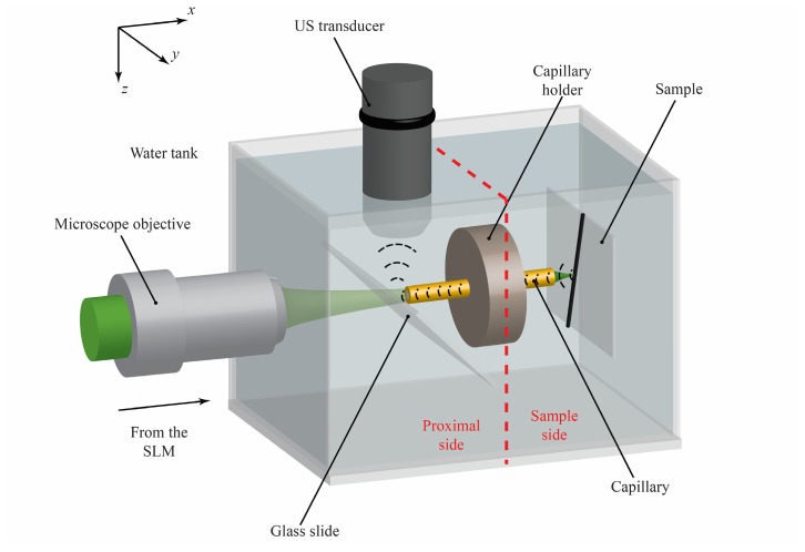
In the case of photoacoustic imaging, the calibration objective OBJ2 is a 20 × objective (NA = 0.42, WD = 20 mm, Mitutoyo, Japan) and OBJ3 is a 10 × objective (NA = 0.28, WD = 33.5 mm, Mitutoyo, Japan). During the PAM experiment we use the polyimide coated CWG (LTSP150375, Polymicro Technologies, USA), which has better performances in terms of guidance and collection of the acoustic waves [22,25] due to its larger inner diameter. The setup shown in Fig. 2 was slightly modified to enable the US collection: the CWG is filled with water and immersed in a water tank (Fig. 3 ). The change in the calibration objective OBJ2 compared to the fluorescence imaging experiment is only due to its reduced dimensions (the 20 × is 75mm-long, while the 50 × is 82 mm-long) and longer working distance that facilitates the accommodation of the water tank without redesigning the optical setup. The capillary holder physically separates the sample side from the proximal side: neither light nor sound waves can pass through it, so the sample is completely inaccessible. Thanks to DPC and the CWG, light focuses on the sample and generates a US wave that travels back to the proximal side through the liquid core. The US wave is reflected upwards by a 150 μm-thick glass slide and is collected by an acoustic transducer (20 MHz, spherically focused, 10.4 mm focal distance, 3.175 mm diameter, Olympus, Japan). The generated electric signal is amplified by a low noise amplifier (DPR500, remote pulser RP-L2, JSR Ultrasonics, USA) and displayed on an oscilloscope. To form the image, the average of 64 photoacoustic signal traces per pixel is recorded on a personal computer for further data processing. The transducer has to be carefully aligned to the hollow core of the CWG in order to be able to detect the US signal. The lateral resolution of the focused transducer used in this experiment, in fact, is comparable to the size of the inner diameter of the CWG. In order to maximize the detected signal, the transducer was first placed on top of CWG. Using the transducer in pulse-echo mode, an US pulse was fired towards the CWG and the position in the z-direction was adjusted to maximize the detected echo signal. Following the CWG wall, the US transducer was shifted along the x-direction up to the glass slide acting as an acoustic reflector. The z-direction was adjusted again in order to detect the echo coming from the facet of the CWG. At this point the transducer was scanned in x and y in order to align it to the center of the CWG facet.
Fig. 3.
The shaped laser beam coming from the SLM is coupled back into the capillary waveguide and creates a sharp focus spot on the sample side. The absorption of nanosecond laser pulse by the sample results in a photoacoustic wave that is guided backwards to the proximal side by the water-filled capillary core, used as an acoustic waveguide. The glass slide is used to deflect the ultrasound (US) signal towards the US transducer. The red dashed line shows the separation between proximal side and sample side. The imaging tip is free of any optical element or transducer, allowing minimally invasive endoscopy.
2.1. Digital phase conjugation through capillary waveguide characterization
The CWG supports a large number of modes. These modes, during propagation, will generate a quasi-random speckle pattern at the end of the waveguide. As explained before, by properly shaping the light using an SLM it is possible to create a focus spot on one end of the CWG. A calibration step is needed to determine the required wavefront.
When the calibration beam is focused on the plane of the capillary facet, two possible situations can happen: the beam is focused on the silica annular part or on the hollow core of the capillary. In the first case, the light is guided to the other side of the capillary, and exits as a speckle pattern (Fig. 4(a) ) that can be recorded and phase conjugated, recreating a focus spot at the original position. The guiding mechanism in this case is total internal reflection, and the size of the phase conjugated spot is given by the maximum angle the optical waveguide can accept (i.e. the NA). Figure 4(b) shows that is possible to scan a focused spot of full width at half maximum (FWHM) of 1.25 μm in a regular grid in the area delimited by the silica walls of the CWG.
Fig. 4.
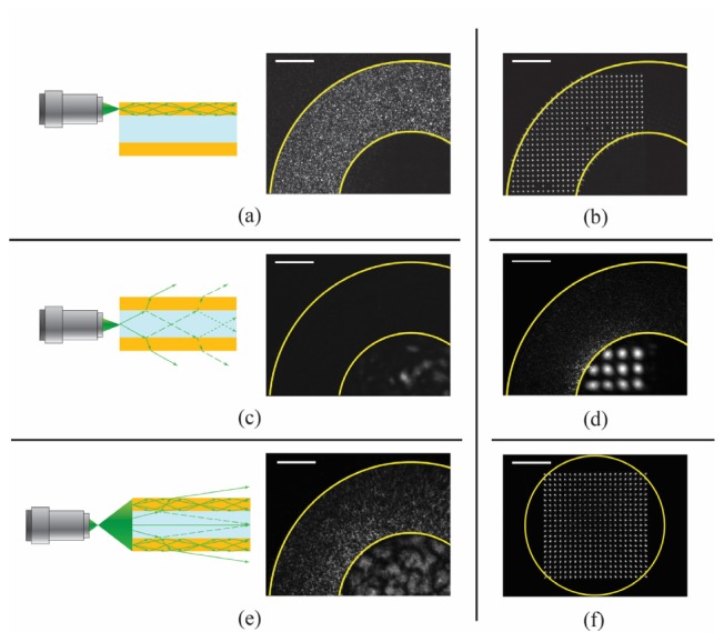
Digital phase conjugation through CWG: (a) During the calibration step, when light is focused directly in the silica part of the CWG, the light gets coupled to the propagation modes of the optical waveguide, so the optical field that exits the CWG on the other side will have a maximum spatial frequency given by the NA of the CWG. The field can be phase conjugated by using an SLM and sent back in the same location, forming a sharp focus; (b) Calibrating the endoscope in several positions it is possible to focus and scan a focus spot with a FWHM = 1.25 μm in a regular grid; (c) Focusing on the hollow core of the CWG, light cannot be coupled into the silica waveguide: light with low propagation angles is reflected better than the one with high angles, which gets lost into radiation modes. The field that exits the CWG has a small spatial spectrum, so the phase conjugated spot has a NA lower than the one of the CWG; (d) Focusing and scanning of a focus spot with a FWHM = 8 μm at the center of CWG; (e) Focusing in a plane at some distance from the capillary facet, it is possible to couple light in the silica part of the CWG even when the objective is focusing at the center of the CWG; (f) A 1.5 μm focused spot is scanned in a regular grid over a 130 × 130 µm2 field of view in a plane 500 μm away from the facet of the CWG. The center of the grid corresponds to the center of the CWG. The elongated shape of the spots on the sides of the grid is given by a not perfect collection of the light during the calibration step. The calibration beam is partially coupled into the CWG due to the working distance and its relative position respect to the CWG. This affects the NA of the spot that can be phase conjugated. (b), (d) and (f) were formed superimposing images of spots focusing at different locations. The exposure time of (d) is 10 times the one used to acquire (b). Scale bars are 50 μm.
On the other hand, if the calibration beam is focused at the hollow core of the CWG, almost no light is going to reach the other side of the waveguide. As shown in Fig. 4(c), light cannot be coupled into the silica part since only radiation modes can be excited in this configuration. Low order spatial modes, instead, are reflected with higher reflectivity and exit the center of the CWG at the proximal side: digital phase conjugation of the recorded field can thus form a focused spot with a lower NA (Fig. 4(d)).
In order to obtain a regular grid of focused spots with high NA also at the center of the CWG, some working distance (WD) has to be added between the CWG facet and the focusing plane (Fig. 4(e)). This is useful especially for photoacoustic imaging where the best US signal collection is obtained when the sample is aligned to the hollow core of the CWG (the acoustic waveguide). Focusing far from the CWG facet and letting the calibration beam diffract for a certain distance, allows us to illuminate the silica part of CWG, generating a high resolution speckle pattern at the proximal side. This leads to the generation of a regular grid of spots with a large field of view, as shown in Fig. 4(f) (the center of the grid corresponds to the center of CWG, the FWHM of the spots is on average 1.5 μm, scale bar 50 µm). The introduction of the WD does not come without a cost. The focused spots at the edges are elongated along the radial direction. The observed aberrations become worse for spots further away from the center of the CWG. When focused towards the edges of the CWG, the calibration beam expands during the diffraction, and part of it misses the capillary facet, limiting the NA of the reconstructed spot via DPC. Knowing the shape of the focused spots, deconvolution algorithms can be used to compensate for the aberration induced by the system.
3. Results and discussion
3.1. Fluorescence imaging
We first demonstrated that the CWG is used as a fluorescence endoscopic device. A computer is used to synchronize the projection of phase conjugated patterns on the SLM and the fluorescence signal acquisition by the CMOS. For this experiment we use a 30 mm-long capillary (Polymicro Technologies, TSU100375, USA). In Fig. 5 we present imaging of fluorescent polystyrene beads with a diameter of 1.5 µm in average, deposited on a glass slide. The fluorescent beads are scanned by focusing spots with the FWHM of 1.5 µm in average at the imaging tip of the CWG, as shown in Fig. 4(f). The number of scanning points is 100 × 100, the step size is 0.31 µm, and the field of view is 31 × 31 µm2. The acquired fluorescence image has been convolved with a Gaussian filter and resampled to minimize pixelation effects (Fig. 5(a)). The cross-sectional plot in Fig. 5(c) shows that two beads 2.2 µm apart could be completely resolved. The comparison between the fluorescence image in Fig. 5(a) and the white light optical image in Fig. 5(b) shows one to one correspondence demonstrating the imaging ability of the CWG used as the fluorescence endoscopic device.
Fig. 5.
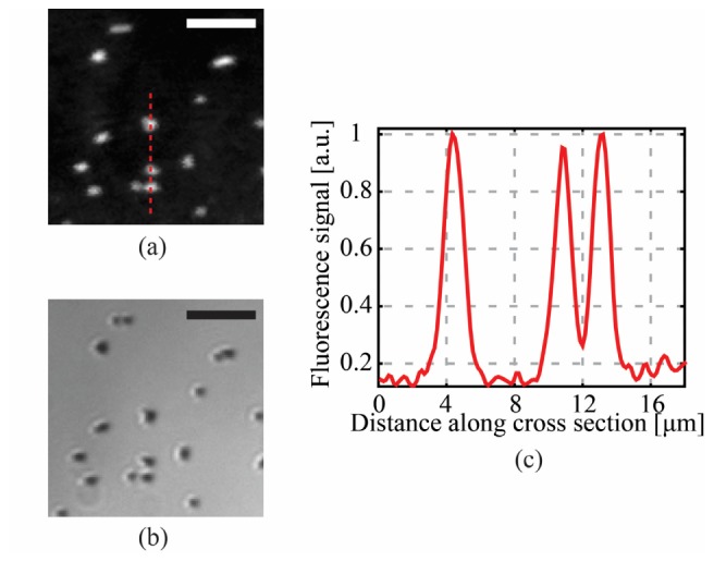
Demonstration of high resolution fluorescence imaging through the CWG: (a) Fluorescence image of 1.5 μm beads in a plane 100 μm away from the CWG facet. The sample is placed in front of the silica part of the CWG in order to maximize resolution and signal collection. The FWHM of the spot is 1.5 μm and the scanning step is 0.31 μm; (b) white light optical image of the sample; (c) cross-sectional plot along the red dashed line in (a) shows that two beads 2.2 μm far apart were completely resolved, giving an upper limit for the resolution of the fluorescence endoscope of about 2 μm. Scale bar are 10 μm.
The curve in Fig. 6 shows how the collection efficiency of the fluorescence signal varies as a function of the WD. The insets show how the loss in signal strength results in reduced signal-noise-ratio.
Fig. 6.
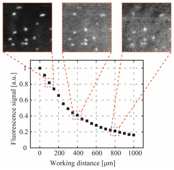
Collection efficiency of the CWG as a function of the working distance. Light is focused using DPC on a fluorescent bead and collected through the CWG. To generate a point in the curve, all the collected signal was integrated. Focus spots can be created very far away from the CWG, but the quality of the fluorescence images degrades due to decrease in collection efficiency.
3.2. Photoacoustic imaging
We also demonstrate the use of the same CWG system as a photoacoustic endoscopic device. For this experiment, we use a 25 mm-long capillary (Polymicro Technologies, LTSP150375, USA) as a CWG. The capillary used in this case has an inner diameter of 150 μm instead of 100 μm, so that the acoustic collection efficiency is optimized [25]. In Fig. 7 we first characterize the PA signal collection while focusing using DPC. The sample is a homogeneously absorbing 23 µm-thick layer of red polyester (color film 60193, Réflectiv, France). Figure 7(a) and Fig. 7(b) respectively show time domain PA signals and their spectra depending on the distance between the sample and the distal tip of the CWG. The images show that the time trace of the signal does not change depending on the WD (apart from shifting in time), but just attenuates. Thus, the frequency content is kept, so no information is lost by the acoustic waveguide in the CWG due to the WD, unless the signal becomes too weak compared to the noise level.
Fig. 7.
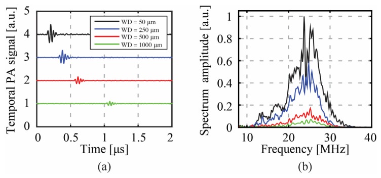
Characterization of photoacoustic signal collection using the CWG: (a) Photoacoustic signals acquired placing the sample at different distances from the CWG tip. Each position along the y-axis corresponds to a different acquisition. (b) Spectral components of the signals shown in (a). The pulse repetition rate of the laser was set to 200 Hz. The pulse energy at each phase conjugated spot was estimated at 500 nJ/pulse.
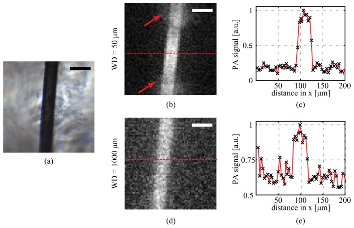
In Fig. 8 we demonstrate optical-resolution photoacoustic imaging of a 30 µm diameter black nylon thread (NYL02DS, Vetsuture, France). In the experiment the number of scanning points is 64 × 64, the step size is 3.45 µm, and the field of view is 220 × 220 µm2. In Fig. 8(b), the nylon thread is imaged at WD = 50 µm and the plot is the cross-section of the PA image along the red dashed line (Fig. 8(c)). The phase conjugated spot was measured to have FWHM = 2.2 µm in the silica region. This is significantly larger compared to resolution we obtained with the fluorescence imaging experiment due to the presence of the water. The resolution of the CWG at the center of the CWG was 8 µm. The arrows in the PA image in Fig. 8(b) point at two areas where the signal collection was limited by the presence of the silica walls of the capillary.
Fig. 8.
Optical resolution photoacoustic imaging through CWG. (a) A black nylon thread (30 µm in diameter) was used as absorber. (b) Digital phase conjugation was used to digitally focus and scan a pulsed laser beam over a field of view of 220 × 220 µm2. At a working distance (WD) of 50 µm it was possible to obtain an image of the thread with an SNR of 10. The two arrows indicate two areas where the collection was limited by the proximity of the sample to the CWG. (c) The cross-section of (b) shows a transition from background to signal between 2 and 3 pixels, giving an upper limit for the resolution around 10 µm. At the center of the CWG in fact, for short WDs the phase conjugated spot has a low numerical aperture. (d) Optical resolution photoacoustic image of the same sample at a WD = 1000 µm. Due to the distance, the collection is more homogeneous within the whole field of view, but the SNR decreases. Since at high WD it is possible to scan with the same high resolution in the entire imaging plane, the resolution obtained in this case improves, with a transition from background to signal between 1 and 2 pixels, as shown in (e). Scale bars are 50 µm.
Increasing the WD, the focus spot at the center of the endoscope decreases in size, the signal collection becomes more homogeneous for a larger field of view, but the signal to noise ratio decreases as well. In Fig. 8(d) we show the PA imaging at a WD = 1000 µm. The phase conjugated spot size was on average 3 µm throughout the imaging plane.
4. Conclusions
We have shown that CWGs can be used not only as a sensor or biosensor, but also as an imaging device, which can bring advantages to minimally invasive endoscopy. We have demonstrated that an ultrathin capillary waveguide can be used as a fully passive imaging device for fluorescence and photoacoustic imaging. Wavefront shaping combined with the possibility to use the CWG as an acoustic and optical multimode waveguide, can be seen as a powerful solution to focus light deep in tissue, picking up fluorescence and photoacoustic signals, while being at the same time minimally invasive.
One limitation of endoscopic approaches based on multimode waveguides is that the required calibration is waveguide shape-dependent. In fact, the modal distribution of a multimode waveguide depends on its spatial conformation. The used CWG, although is stiffer than usual MMFs, could be affected by the same problem. One possible approach is to insert the CWG in a rigid needle, in order to give mechanical stability [8]. Our CWG, in fact, would fit in a 23 gauge needle. Another possibility is to run calibrations for different bending states in order to create a discrete number of phase lookup tables, as proposed in [26]. Recently it was also demonstrated that is possible to calculate the right phase pattern in order to project and scan a focused spot through a MMF without any calibration step [27]. The patterns to project the focused spot in a regular grid could be calculated real time while bending the fiber, using as a feedback the quality of the image.
The modal distribution in a multimode waveguide can also be affected by temperature. Recently it was calculated that using a 1 meter-long multimode fiber, a temperature variation ΔT = 8°C is necessary to completely decorrelate the modal distribution [28]. Since ΔT decreases linearly with the length of the multimode waveguide, CWGs are suitable for most kind of endoscopic approaches providing an initial calibration at human body temperature.
A custom-made CWG with an optimized hollow core size and silica walls thickness would allow to make the two measurements at the same time. This will lead to a rigid endoscopic device that measures only 330 µm in diameter. The possibility of acquiring through the same endoscope fluorescence and photoacoustic signal can give complementary information about the interrogated sample. This can be extremely helpful, for example, in case of early-stage cancer diagnosis. The fluorescence contrast images can give information about the morphology of the cells. At the same time, an absorption map of the tissue can be obtained using the photoacoustic capability, which can give high contrast label-free images of tumor masses, tissue vascularization and blood saturation.
Optical resolution photoacoustic imaging was demonstrated by imaging a 30 µm nylon thread. In order to maximize the US signal collection, the sample had to be placed right in front the hollow core. For small working distances it is possible to focus a low NA focus spot, obtaining a resolution below 10 µm, and reconstructing an image by collecting US waves through the CWG. It is possible to obtain high NA focused spots in the entire imaging plane by increasing the working distance, so an image with a better resolution can be obtained at the cost of a lower signal to noise ratio. One possible solution to this problem and also reduce the working distance is to increase the NA of the optical waveguide, or changing the materials composing the CWG or introducing a scattering layer at the imaging tip [29,30]. The second option would increase the photoacoustic imaging capability at the expenses of the fluorescence imaging, since the fluorescence collection efficiency will decrease. Another possible approach would be to coat the walls of the hollow core with a carpet of polystyrene particles acting as small prisms, in order to couple the calibration beam (and the fluorescence light to collect) into the propagation modes of the CWG.
Moreover, engineering the light and acoustic guidance properties of the CWG, and integrating the device with an acoustic beam splitter as in [31] and [32], would improve the acoustic signal collection and detection efficiency. A Teflon coated CWG with an inner diameter larger than the ones commercially available (150 μm for example) would also improve the endoscope. In fact Teflon coated capillaries have the peculiarity of guiding light also in the liquid core when filled with water. This happens because the cladding has a refractive of 1.31, which is lower than the water’s one (1.33). At this point no WD is needed and a high NA focus spot can be formed everywhere in front of the CWG.
We believe that the results presented in this work pave the way for an ultrathin and high resolution endoscopic device, able to image with different modalities deep inside biological tissues, still being at the same time minimally invasive, with a total diameter of only 330 µm and no optical or acoustic elements on the imaging side.
At the same time, we think that this work will arouse curiosity around this kind of waveguides and trigger new research, looking for new possible applications combining light focusing through the multimode optical waveguide and the direct access on both sides of the waveguide itself.
Acknowledgments
This project was conducted partially with the support of the Bertarelli Foundation under the grant “Optical Imaging of the Inner Ear for cellular Diagnosis and Therapy: Cochlear Implants and Beyond”. This work was partially funded by LABEX WIFI (Laboratory of Excellence within the French Program “Investments for the Future”) under references ANR-10-LABX-24 and ANR-10-IDEX-0001-02 PSL*. Olivier Simandoux gratefully acknowledges funding from the French Direction Generale de l’Armement (DGA).
References and links
- 1.Wolfbeis O. S., “Capillary waveguide sensors,” TrAC, Trends Analyt. Chem. 15(6), 225–232 (1996). 10.1016/0165-9936(96)85131-4 [DOI] [Google Scholar]
- 2.Borecki M., Korwin-Pawlowski M. L., Beblowska M., Szmidt J., Jakubowski A., “Optoelectronic Capillary Sensors in Microfluidic and Point-of-Care Instrumentation,” Sensors (Basel) 10(4), 3771–3797 (2010). 10.3390/s100403771 [DOI] [PMC free article] [PubMed] [Google Scholar]
- 3.Flusberg B. A., Cocker E. D., Piyawattanametha W., Jung J. C., Cheung E. L. M., Schnitzer M. J., “Fiber-optic fluorescence imaging,” Nat. Methods 2(12), 941–950 (2005). 10.1038/nmeth820 [DOI] [PMC free article] [PubMed] [Google Scholar]
- 4.Oh G., Chung E., Yun S. H., “Optical fibers for high-resolution in vivo microendoscopic fluorescence imaging,” Opt. Fiber Technol. 19(6), 760–771 (2013). 10.1016/j.yofte.2013.07.008 [DOI] [Google Scholar]
- 5.Bianchi S., Di Leonardo R., “A multi-mode fiber probe for holographic micromanipulation and microscopy,” Lab Chip 12(3), 635–639 (2012). 10.1039/C1LC20719A [DOI] [PubMed] [Google Scholar]
- 6.Papadopoulos I. N., Farahi S., Moser C., Psaltis D., “Focusing and scanning light through a multimode optical fiber using digital phase conjugation,” Opt. Express 20(10), 10583–10590 (2012). 10.1364/OE.20.010583 [DOI] [PubMed] [Google Scholar]
- 7.Cižmár T., Dholakia K., “Exploiting multimode waveguides for pure fibre-based imaging,” Nat. Commun. 3, 1027 (2012). 10.1038/ncomms2024 [DOI] [PMC free article] [PubMed] [Google Scholar]
- 8.Papadopoulos I. N., Farahi S., Moser C., Psaltis D., “High-resolution, lensless endoscope based on digital scanning through a multimode optical fiber,” Biomed. Opt. Express 4(2), 260–270 (2013). 10.1364/BOE.4.000260 [DOI] [PMC free article] [PubMed] [Google Scholar]
- 9.Zhang H. F., Maslov K., Stoica G., Wang L. V., “Functional photoacoustic microscopy for high-resolution and noninvasive in vivo imaging,” Nat. Biotechnol. 24(7), 848–851 (2006). 10.1038/nbt1220 [DOI] [PubMed] [Google Scholar]
- 10.Maslov K., Stoica G., Wang L. V., “In vivo dark-field reflection-mode photoacoustic microscopy,” Opt. Lett. 30(6), 625–627 (2005). 10.1364/OL.30.000625 [DOI] [PubMed] [Google Scholar]
- 11.Shao P., Shi W., Hajireza P., Zemp R. J., “Integrated micro-endoscopy system for simultaneous fluorescence and optical-resolution photoacoustic imaging,” J. Biomed. Opt. 17(7), 076024 (2012). 10.1117/1.JBO.17.7.076024 [DOI] [PubMed] [Google Scholar]
- 12.Maslov K., Zhang H. F., Hu S., Wang L. V., “Optical-resolution photoacoustic microscopy for in vivo imaging of single capillaries,” Opt. Lett. 33(9), 929–931 (2008). 10.1364/OL.33.000929 [DOI] [PubMed] [Google Scholar]
- 13.Xie Z., Jiao S., Zhang H. F., Puliafito C. A., “Laser-scanning optical-resolution photoacoustic microscopy,” Opt. Lett. 34(12), 1771–1773 (2009). 10.1364/OL.34.001771 [DOI] [PubMed] [Google Scholar]
- 14.Beard P., “Biomedical photoacoustic imaging,” Interface Focus 1(4), 602–631 (2011). [DOI] [PMC free article] [PubMed] [Google Scholar]
- 15.Wang L. V., Hu S., “Photoacoustic Tomography: In Vivo Imaging from Organelles to Organs,” Science 335(6075), 1458–1462 (2012). 10.1126/science.1216210 [DOI] [PMC free article] [PubMed] [Google Scholar]
- 16.Hajireza P., Shi W., Zemp R. J., “Label-free in vivo fiber-based optical-resolution photoacoustic microscopy,” Opt. Lett. 36(20), 4107–4109 (2011). 10.1364/OL.36.004107 [DOI] [PubMed] [Google Scholar]
- 17.Yang J.-M., Maslov K., Yang H.-C., Zhou Q., Shung K. K., Wang L. V., “Photoacoustic endoscopy,” Opt. Lett. 34(10), 1591–1593 (2009). 10.1364/OL.34.001591 [DOI] [PMC free article] [PubMed] [Google Scholar]
- 18.Yang J.-M., Chen R., Favazza C., Yao J., Li C., Hu Z., Zhou Q., Shung K. K., Wang L. V., “A 2.5-mm diameter probe for photoacoustic and ultrasonic endoscopy,” Opt. Express 20(21), 23944–23953 (2012). 10.1364/OE.20.023944 [DOI] [PMC free article] [PubMed] [Google Scholar]
- 19.Yang J.-M., Li C., Chen R., Rao B., Yao J., Yeh C.-H., Danielli A., Maslov K., Zhou Q., Shung K. K., Wang L. V., “Optical-resolution photoacoustic endomicroscopy in vivo,” Biomed. Opt. Express 6(3), 918–932 (2015). 10.1364/BOE.6.000918 [DOI] [PMC free article] [PubMed] [Google Scholar]
- 20.Papadopoulos I. N., Simandoux O., Farahi S., Huignard J. P., Bossy E., Psaltis D., Moser C., “Optical-resolution photoacoustic microscopy by use of a multimode fiber,” Appl. Phys. Lett. 102(21), 211106 (2013). 10.1063/1.4807621 [DOI] [Google Scholar]
- 21.Wells P. N. T., “Ultrasonic imaging of the human body,” Rep. Prog. Phys. 62(5), 671–722 (1999). 10.1088/0034-4885/62/5/201 [DOI] [Google Scholar]
- 22.Simandoux O., Stasio N., Gateau J., Huignard J.-P., Moser C., Psaltis D., Bossy E., “Optical-resolution photoacoustic imaging through thick tissue with a thin capillary as a dual optical-in acoustic-out waveguide,” Appl. Phys. Lett. 106(9), 094102 (2015). 10.1063/1.4913969 [DOI] [Google Scholar]
- 23.Saleh B. E. A., Teich M. C., Fundamentals of Photonics (Wiley, 2013). [Google Scholar]
- 24.Blackstock D. T., Fundamentals of Physical Acoustics (John Wiley & Sons, 2000). [Google Scholar]
- 25.O. Simandoux, “Photoacoustic imaging: contributions to optical-resolution photoacoustic endoscopy and experimental investigation of thermal nonlinearity,” PhD thesis, Université Paris Diderot Paris 7 (2015).
- 26.Farahi S., Ziegler D., Papadopoulos I. N., Psaltis D., Moser C., “Dynamic bending compensation while focusing through a multimode fiber,” Opt. Express 21(19), 22504–22514 (2013). 10.1364/OE.21.022504 [DOI] [PubMed] [Google Scholar]
- 27.Plöschner M., Tyc T., Čižmár T., “Seeing through chaos in multimode fibres,” Nat. Photonics 9(8), 529–535 (2015). 10.1038/nphoton.2015.112 [DOI] [Google Scholar]
- 28.Redding B., Popoff S. M., Cao H., “All-fiber spectrometer based on speckle pattern reconstruction,” Opt. Express 21(5), 6584–6600 (2013). 10.1364/OE.21.006584 [DOI] [PubMed] [Google Scholar]
- 29.Papadopoulos I. N., Farahi S., Moser C., Psaltis D., “Increasing the imaging capabilities of multimode fibers by exploiting the properties of highly scattering media,” Opt. Lett. 38(15), 2776–2778 (2013). 10.1364/OL.38.002776 [DOI] [PubMed] [Google Scholar]
- 30.Choi Y., Yoon C., Kim M., Yang J., Choi W., “Disorder-mediated enhancement of fiber numerical aperture,” Opt. Lett. 38(13), 2253–2255 (2013). 10.1364/OL.38.002253 [DOI] [PubMed] [Google Scholar]
- 31.Hu S., Yan P., Maslov K., Lee J.-M., Wang L. V., “Intravital imaging of amyloid plaques in a transgenic mouse model using optical-resolution photoacoustic microscopy,” Opt. Lett. 34(24), 3899–3901 (2009). 10.1364/OL.34.003899 [DOI] [PMC free article] [PubMed] [Google Scholar]
- 32.Hu S., Maslov K., Wang L. V., “Second-generation optical-resolution photoacoustic microscopy with improved sensitivity and speed,” Opt. Lett. 36(7), 1134–1136 (2011). 10.1364/OL.36.001134 [DOI] [PMC free article] [PubMed] [Google Scholar]


