

Abstract:
During the course of extracorporeal membrane oxygenation, patients are at constant risk of exposure to air emboli. Air emboli may enter the circuit during routine lab sampling, medication administration, air entrainment through the venous cannula, or via a circuit disruption. Circuit components have been designed and positioned to minimize the quantity of air that travels through the arterial line to the patient. The purpose of this study was to assess the air handling of a newer generation extracorporeal life support circuit. The extracorporeal life support circuit consisted of an open hard-shell venous reservoir, Better Bladder (BB14) or silicone bladder (R-14), and Quadrox D® oxygenator or 0800 silicone oxygenator. Air emboli detection sensors were placed in the extracorporeal life support circuit: post bladder, post oxygenator, and post heat exchanger if applicable. Air was injected as a 1 mL/min for 5 minutes injection or as a single 5 mL bolus. Emboli detection was recorded continuously during and for 3 minutes post air injection at two blood flow rates (Qb) (.5 and 1.2 L/min). All tests were performed in triplicate with each condition. All tested components reduced the embolic volume transmitted through the circuit. The quantity of this reduction was dependent on both the Qb and the air injection condition. During this in-vitro testing, air emboli passing through any of the components tested was decreased. Furthermore, the emboli delivery was reduced post component with the slower Qb (.5 L/min).
Keywords: Emboli Detection and Classification Quantifier, gaseous microemboli, arterial line filter, extracorporeal life supports, extracorporeal membrane oxygenation
Historically, the Kolobow oxygenator with silicone membrane was the device of choice for extracorporeal membrane oxygenation (ECMO) applications due to longevity and absence of plasma leakage. The silicone membrane oxygenator is still available today in a variety of sizes, ranging from 0600 (.6 m2) to 4500 (4.5 m2) through Medtronic (Medtronic, Minneapolis, MN). With the advent of a hollow fiber diffusion membrane oxygenator, Quadrox D® (Maquet Cardiopulmonary, Hirrlingen, Germany), the benefits seen with the Kolobow oxygenator (no plasma leakage) and the low pressure drop associated with hollow fiber oxygenators quickly made this oxygenator appealing for use in ECMO. Likewise, the silicone bladder ((R-14) Medtronic, Minneapolis, MN) has long been the compliance chamber/venous reservoir within the ECMO circuit venous limb. As a compliance chamber, the bladder served to protect the patient from potential excessive negative pressure. The Better Bladder ((BB14) Circulation Technology, Inc., Oyster Bay, NY) is a newer generation compliance chamber within the ECMO circuit and has the potential added benefits of: 1) reduced venous line length, 2) increased durability afforded by the rigid outer housing, and 3) responsiveness to volume change during institutional in-vitro evaluation. Recently all Medtronic 0800 silicone oxygenators and R-14 components were replaced with Quadrox D® oxygenators and the BB14 within this institution’s ECMO circuits.
Despite the wide use of the 0800 oxygenator and R-14 venous reservoir for ECMO in the United States, little data exists surrounding the ability of these components to deal with gaseous microemboli (GME). Various authors have described the sources of GME found within the blood path during cardiopulmonary bypass (CPB), but one must extrapolate this information to the field of ECMO (1–8). The presence of GME within the CPB circuit and ultimately its delivery to the patient is associated with increased morbidity and mortality (1–4,9,10). Applying the knowledge gained through the use of transcranial Doppler of the middle cerebral artery and GME detection within the CPB circuit during cardiac surgery, it is postulated that a correlation between GME presence and their delivery to the patient’s brain exists (5,10). Since the inception of extracorporeal life supports (ECLS) and specifically ECMO, GME delivery has presented a challenge and is potentially an under-reported sequela to the application of this therapy. GME may be introduced and remain present within the ECLS circuit as early as the priming phase, or generated within the ECMO circuit through various means (6,11–13). GME may be introduced into the ECMO circuit by the ECMO specialist in the course of blood sampling or during blood and medication administration (7,8,12). GME may additionally be generated through excess negative pressure applied to the venous cannula or through over occlusion of the roller heads (2,4,13–15). Once in the circuit, removal of GME may best be accomplished by an arterial line filter (ALF) with minimal pore size (1,2,4,16,17). Many authors have shown ALFs reduce GME count and volume during CPB, but ALFs are not a traditional component in conventional ECMO circuits (8,14,16,17). While not well studied, various other components of the ECLS circuit reduce the transmission of GME whether by design or by positioning within the ECMO circuit, and include oxygenators, reservoirs, compliance chambers and heat exchangers, which reduce the GME count/volume in varying degrees (18).
The goal of this experiment was to compare and quantify the volume of GME transmitted through two in-vitro ECLS circuits currently used for the purpose of ECMO.
MATERIALS AND METHODS
Two different ECLS circuits were prepared. The first circuit (A) evaluated consisted of a hard-shell cardiotomy reservoir (simulating the patient) with an integral 40 μ filter (Medtronic, Minneapolis, MN) (Figure 1). The reservoir outlet was attached to a fixed length of 1/4″ × 1/16″ venous tubing connected to the BB14. The BB14 was then connected to a fixed length of 3/8″ × 3/32″ S-95-E (Saint-Gobain, Akron, OH) raceway to a Quadrox D ® oxygenator (Food and Drug Administration approval for use restricted to six hours) and finally, to a fixed length 1/4″ × 1/16″ arterial line, returning to the top of the cardiotomy reservoir. The Emboli Detection and Classification Quantifier (EDAC) was attached to the circuit via air emboli detection cuvettes and sensors (Luna Innovations Inc., Blacksburg, VA) that were placed in the ECLS circuit; 6 inches post BB14 and 6 inches post Quadrox D® (Figure 1). In accordance with the manufacturer’s instructions for use (IFU), the EDAC is capable of identifying (counts) and quantifying (volume) GME down to 10 μ and was therefore sensitive enough for use in this experiment. This enabled quantification of initial air injection or bolus eventually passing through the different components of each circuit.
Figure 1.

Diagram of circuit A, Quadrox D® and Better Bladder.
The second circuit (B) also consisted of a hard-shell cardiotomy reservoir with an integral 40 μ filter, a fixed length of 1/4″ × 1/16″ venous tubing connected to an R-14, then to a fixed length of 3/8″ × 3/32″ S-95-E raceway (Figure 2). The raceway was stepped down to 1/4″ × 1/16″ tubing and attached to the 0800 silicone oxygenator, then to a fixed length of 1/4″ × 1/16″ tubing to an ECMOtherm heat exchanger (Medtronic, Minneapolis, MN) and finally to a fixed length of 1/4″ × 1/16″ arterial line returning to the top of the cardiotomy reservoir. EDAC cuvettes and sensors were placed in the ECLS circuit six inches post bladder (R-14), 6 inches post 0800, and 6 inches post heat exchanger (Figure 2).
Figure 2.
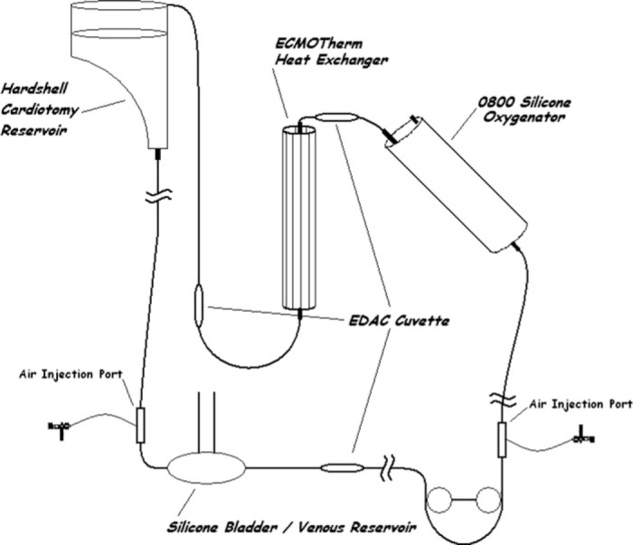
Diagram of circuit B, Silicone 0800 oxygenator, ECMOtherm heat exchanger, and silicone bladder.
Both circuits were placed on a Maquet HL-20 (Maquet Cardiopulmonary, Hirrlingen, Germany) utilizing a single roller pump. Both circuits were primed per manufacturer’s IFU with Normosol-R (Hospira, Inc., Lake Forest, IL) and recirculated through a .2 μ pre bypass filter (Medtronic, Minneapolis, MN) for a minimum of 15 minutes or until no emboli were detected on the EDAC. Roller head occlusion was set to a pressure drop of 50 mmHg/sec (±10 mmHg/sec). The hardshell reservoirs were subsequently drained and filled with human packed red blood cells and fresh frozen plasma to a final hematocrit of 33% (±2%). Once primed, the circuits were recirculated at 37°C and corrected to a pH of 7.4, pCO2 40 ± 10 mmHg, and pO2 150 ± 50 mmHg.
Each circuit component was then evaluated at two blood flow rates (Qb) .5 and 1.2 L/min. Circuit pressure was monitored and recorded during the evaluation. The maximum pre-oxygenator pressure for circuit A was 100 mmHg and for circuit B was 350 mmHg. The maximum negative pressure on the venous/inlet side for circuit A was −17 mmHg and circuit B was −6 mmHg. At each Q b, air was injected at a rate of 1 mL/min × 5 minutes (AS), then as a single 5 mL bolus (AB) prior to the component being tested. Air was not injected immediately prior to the ECMOtherm heat exchanger as this device was tested in conjunction with the 0800. Each component was tested at each blood flow rate (.5 L/min or 1.2 L/min) with each air injection (1 mL/min or 5 mL bolus) three times. Data was collected throughout the injection period and for three consecutive minutes post completion of air injection.
Blood flow rates were chosen based on minimum Qb as determined by the manufacturer’s IFU (Quadrox D®) and maximum recommended Qb as determined by the manufacturer’s IFU (0800 silicone oxygenator). Statistical analysis was completed utilizing a single tailed, paired Student’s t Test on Microsoft Excel (Microsoft Corp., Redmond,WA) with significance defined as p < .05.
RESULTS
The R-14 bladder and the BB14 both decreased the volume of GME passing through the respective component during the AS injection scenario at the lower Qb (.5 L/min) compared to the AB injection (Figure 3). At the higher Qb (1.2 L/min) both performed better when dealing with the AB injection than with the A S injection (Figure 4). The R-14 bladder removed significantly (p < .05) more GME at the higher Qb flow rate with both types of air injection than the Better Bladder. As individual components, the R-14 performed better than the BB14 at both flow rates and injection scenarios (Figures 3 and 4) with regards to GME removal.
Figure 3.

Comparison of the silicone bladder (R-14) to the better bladder (BB14) at Qb .5 L/min with both a 1 mL/min × 5 minutes air injection (AS) (R-14 = .0001 (±.0001)), (BB14 = .0018 (±.002)) and 5 mL air bolus (AB) (R-14 = .0005 (±.0006)), (BB14 = .011 (±.014)). GME volume is total measured during trial time.
Figure 4.

Comparison of the silicone bladder (R-14) to the better bladder (BB14) at Qb 1.2 L/min with both a 1 mL/min × 5 minutes air injection (R-14 = .007 (±.0006)), (BB14 = .057 (±.029))*(p < .05) (AS) and 5 mL air bolus (R-14 = .002 (±.0003)), (BB14 = .053 (±.017))*(p < .05)(AB). GME volume is total measured during trial time.
Evaluation of the oxygenators demonstrated that the Quadrox D® was better than the 0800 silicone membrane oxygenator alone at handling injected air (ASor AB) at both blood flow rates (Figures 5 and 6). Both oxygenators appeared to be less capable of handling the AB compared to the AS at both flow rates (Figures 5 and 6).
Figure 5.

Comparison of the Quadrox D® (QD) to the 0800 silicone oxygenator (0800) alone at Qb .5 L/min with both a 1 mL/min × 5 minutes air injection (AS) (QD = .00001 (±.000008)), (0800 =.00016 (±.00013)) and 5 mL air bolus (AB) (QD = .00032 (±.00028)), (0800 = .00010 (±.00015)). GME volume is total measured during trial time.
Figure 6.

Comparison of the Quadrox D ® (QD) to the 0800 silicone oxygenator (0800) alone at Qb 1.2 L/min with both a 1 mL/min × 5 minutes air injection (AS) (QD = .00072 (±.00009)), (0800 = .069 (±.037)) *(p < .05) and 5 mL air bolus (AB) (QD = .0012 (±.0011)), (0800 = .117 (±.062)). GME volume is total measured during trial time.
Finally, the circuit consisting of the angled silicone membrane oxygenator and vertical ECMOtherm heat exchanger was evaluated for air handling versus the integral heat exchanger of the Quadrox D® circuit. The addition of the separate heat exchanger in the conventional circuit (B) improved its performance over the newer circuit (A) at Qb .5 L/min with both air injection (AS or AB) scenarios, but did not reach statistical significance (Figure 7). However, the benefit of this added air trap was not realized at the higher Qb with either air injection (AS or AB) scenario with the Quadrox D® being significantly better (p < .05) at decreasing the volume of GME (Figure 8). At the maximum tested blood flow rate, initial benefits of orientation and length with the separate heat exchanger are overcome, and air is simply passed through the device. At the lower blood flow rate the heat exchanger is able to reduce transmission due to its orientation and length.
Figure 7.

Comparison of the Quadrox D® (Circuit A) to the 0800 silicone oxygenator and separate ECMOtherm heat exchanger (Circuit B) at Qb .5 L/min with both a 1 mL/min × 5 minutes air injection (AS) (Circuit A = .00001 (±.000008)), (Circuit B = .000006 (±.000003)) and 5 mL air bolus (AB) (Circuit A = .00032 (±.00028)), (Circuit B = .00014 (±.000006)). GME volume is total measured during trial time.
Figure 8.

Comparison of the Quadrox D ® (Circuit A) to the 0800 silicone oxygenator and separate ECMOtherm heat exchanger (Circuit B) at Qb 1.2 L/min with both a 1 mL/min × 5 minutes air injection (Circuit A = .00072 (±.00009)), (Circuit B = .0036 (±.0043)) *(p < .05)(AS) and 5 mL air bolus (Circuit A = .0012 (±.0011)), (Circuit B = .013 (±.0057))*(p < .05)(AB). GME volume is total measured during trial time.
DISCUSSION
Many ECLS components are used to minimize air movement through the circuit to the patient. The conventional (R-14) bladder is designed such that, when oriented horizontally within the venous line, the reservoir represents an area of lower blood velocity, which allows GME to migrate up towards the top of the bladder where removal may be accomplished. The BB14 has a smaller reservoir area and is typically oriented vertically within the venous line, which may allow for an overall shorter venous limb. The velocity of blood through the BB14 (due to the smaller reservoir) may in part explain the lower volume of GME that passed through the R-14 bladder when compared to the BB14. The orientation of the 0800 is generally such that when in position, the arterial outlet is lower than an integral luer connector on the outlet side. This luer connector being at the highest point allows for removal of air. Alternately, the Quadrox D® was designed with a de-airing membrane at the high point on the blood inlet side for passive air removal. This luered port consists of a hydrophobic membrane that allows for the passage of air but not fluid. This port should be kept closed during normal operation per manufacturer’s IFU. If air is visible in the oxygenator during use, it can be opened allowing air removal, then closed. This de-airing port remained closed throughout this experiment.
Many conventional ECMO circuits have an additional GME trapping device in the separate heat exchanger. Oriented vertically with flow from top-to-bottom, GME not caught by the other circuit constituents may be detained at the top of this device for future removal. At higher Qb, the benefit of this orientation and length of the heat exchanger was overcome due to velocity, and GME simply passed through the device. The Quadrox D® heat exchanger is integral and therefore does not have this additional air trapping or removal feature.
To our knowledge, no prior studies have evaluated ECMO circuit components for air handling ability using the EDAC quantifier or comparable GME detection device. In the recent transition to a diffusion membrane oxygenator and BB14, a comparative evaluation was needed to determine if GME transmission rate was at least equivalent with the 0800, bladder (R-14), and separate heat exchanger circuit configuration. The results show that both circuits protected against gross transmission of potentially harmful GME through the extracorporeal circuit. This was demonstrated by comparing the volume of air introduced to each circuit with the volume of air quantified beyond each device. Individual components performed differently, but when included with the other constituents of an ECLS circuit, much of the entrained GME was eliminated from the blood path.
Ideally, an ALF or bubble trap would be a part of every ECLS circuit. However, because of the associated increase in prime volume, increase in circuit surface area, and increased risk of thrombus formation, this has not been practiced (19). Recently, oxygenators with integral ALFs have been introduced for use during cardiopulmonary bypass. Unfortunately, none of the current devices are approved for ECLS (greater than 6 hours) in the United States. As this and previous studies have demonstrated, a microemboli load may pass through these circuits ending ultimately in the patient (2–5,9,10). The use of the newer oxygenators with integral ALFs may well be worth evaluating in ECLS circuits as soon as a genuine diffusion membrane option is available.
This evaluation has shed some light on the ECLS constituent’s ability to handle GME. A primary limitation of this study was the duration (minutes), whereas most ECMO patients are supported on ECMO for days to weeks. With this knowledge, even a small volume of GME/min could lead to a dangerous embolic load over time. Vigilance when setting occlusion, priming and accessing the circuit is the primary means of reducing this potential GME.
Further, GME reduction through improved circuit components and potentially an ALF should be recognized, but not depended upon nor replace vigilance. More detailed follow-up studies encompassing an entire ECMO run are warranted.
REFERENCES
- 1.Undar A, Ji B, Kunselman AR, Myers JL.. Detection and classification of gaseous microemboli during pulsatile and nonpulsatile perfusion in a simulated neonatal CPB model. ASAIO J. 2007;53:725–9. [DOI] [PubMed] [Google Scholar]
- 2.Win KN, Wang S, Undar A.. Microemboli generation, detection and characterization during CPB procedures in neonates, infants, and small children. ASAIO J. 2008;54:486–90. [DOI] [PubMed] [Google Scholar]
- 3.Schreiner RS, Rider AR, Myers JW, et al. Microemboli detection and classification by innovative ultrasound technology during simulated neonatal cardiopulmonary bypass at different flow rates, perfusion modes, and perfusate temperatures. ASAIO J. 2008;54:316–24. [DOI] [PubMed] [Google Scholar]
- 4.Butler B.. Gaseous micro emboli: Concepts and considerations. J Extra Corpor Technol. 1983;15:148–55. [Google Scholar]
- 5.Lynch JE, Riley JB.. Microemboli detection on extracorporeal bypass circuits. Perfusion. 2008;23:23–32. [DOI] [PubMed] [Google Scholar]
- 6.Groom RC, Froebe S, Martin J, et al. Update on pediatric perfusion practice in North America: 2005 Survey. J Extra Corpor Technol. 2005;37:343–50. [PMC free article] [PubMed] [Google Scholar]
- 7.Myers G.. Preventing gaseous microemboli during blood sampling and drug administration:An in vitro investigation. J Extra Corpor Technol. 2007;39:192–8. [PMC free article] [PubMed] [Google Scholar]
- 8.Preston TJ, Gomez D, Olshove VF, Phillips A, Galantowicz M.. Clinical gaseous microemboli assessment of an oxygenator with integral arterial filter in the pediatric population. J Extra Corpor Technol. 2009;41:226–30. [PMC free article] [PubMed] [Google Scholar]
- 9.Barak M, Katz Y.. Microbubbles: pathophysiology and clinical implications. Chest. 2005;128:2918–32. [DOI] [PubMed] [Google Scholar]
- 10.Diegeler A, Hirsch R, Schneider F, et al. Neuromonitoring and neurocognitive outcome in off-pump versus conventional coronary bypass operation. Ann Thorac Surg. 2000;69:1162–6. [DOI] [PubMed] [Google Scholar]
- 11.Merkle F, Bottcher W, Hetzer R.. Prebypass filtration of cardiopulmonary bypass circuits: An outdated technique? Perfusion. 2003;18:81–8. [DOI] [PubMed] [Google Scholar]
- 12.Merkle F, Boettcher W, Schulz F, et al. Reduction of microemboli count in the priming fluid of cardiopulmonary bypass circuits. J Extra Corpor Technol. 2003;35:133–8. [PubMed] [Google Scholar]
- 13.Kurusz M, Conti VR, Speer D, Butler BD.. Surface tension changes of perfusates: Implications for gaseous microemboli during cardiopulmonary bypass. J Extra Corpor Technol. 1985;17:138–42. [Google Scholar]
- 14.Wang S, Win KN, Kunselman AR, Woitas K, Myers JL, Undar A.. The capability of trapping gaseous microemboli of two pediatric arterial filters with pulsatile and nonpulsatile flow in a simulated infant CPB model. ASAIO J. 2008;54:519–22. [DOI] [PubMed] [Google Scholar]
- 15.Jones TJ, Deal DD, Vernon JC, Blackburn N, Stump DA.. How effective are cardiopulmonary bypass circuits at removing gaseous micro-emboli? J Extra Corpor Technol. 2002;34:34–9. [PubMed] [Google Scholar]
- 16.Riley JB.. Arterial line filters ranked for gaseous micro-emboli separation performance: An in vitro study. J Extra Corpor Technol. 2008;40:21–6. [PMC free article] [PubMed] [Google Scholar]
- 17.Gomez D, Preston TJ, Olshove VF, Phillips AB, Galantowicz ME.. Evaluation of air handling in a new generation neonatal oxygenator with integral arterial filter. Perfusion. 2009;24:107–12. [DOI] [PubMed] [Google Scholar]
- 18.De Somer F.. Impact of oxygenator characteristics on its capability to remove gaseous microemboli. J Extra Corpor Technol. 2007;39: 271–3. [PubMed] [Google Scholar]
- 19.Lawson SD, Lawson AF, Walczak R, et al. North American neonatal extracorporeal membrane oxygenation (ECMO) devices and team roles: 2008 survey results of extracorporeal life support organization (ELSO) centers. J Extra Corpor Technol. 2008;40:166–74. [PMC free article] [PubMed] [Google Scholar]