Abstract
Eight welding processes/shielding gas combinations were assessed for generation of hexavalent chromium (Cr6+) in stainless steel welding fumes. The processes examined were gas metal arc welding (GMAW) (axial spray, short circuit, and pulsed spray modes), flux cored arc welding (FCAW), and shielded metal arc welding (SMAW). The Cr6+ fractions were measured in the fumes; fume generation rates, Cr6+ generation rates, and Cr6+ generation rates per unit mass of welding wire were determined. A limited controlled comparison study was done in a welding shop including SMAW, FCAW, and three GMAW methods. The processes studied were compared for costs, including relative labor costs. Results indicate the Cr6+ in the fume varied widely, from a low of 2800 to a high of 34,000 ppm. Generation rates of Cr6+ ranged from 69 to 7800 μg/min, and Cr6+ generation rates per unit of wire ranged from 1 to 270 μg/g. The results of field study were similar to the findings in the laboratory. The Cr6+ (ppm) in the fume did not necessarily correlate with the Cr6+ generation rate. Physical properties were similar for the processes, with mass median aerodynamic diameters ranging from 250 to 336 nm, while the FCAW and SMAW fumes were larger (360 and 670 nm, respectively). Conclusion: The pulsed axial spray method was the best choice of the processes studied based on minimal fume generation, minimal Cr6+ generation, and cost per weld. This method is usable in any position, has a high metal deposition rate, and is relatively simple to learn and use.
Keywords: Hexavalent Chromium, Stainless Steel, Gas Metal Arc Welding (GMAW), Flux Cored Arc Welding (FCAW), Shielded Metal Arc Welding (SMAW), Welding Fume
Introduction
Welding is a major occupational activity in the United States and worldwide, and includes workers in manufacturing, construction, and a number of other industrial sectors. In excess of 462,000 U.S. workers do some welding as part of their duties (Ref. 1), and about two-thirds of these workers are in manufacturing industries. Welding produces a number of hazards during operation, including fumes, gases, and physical agents such as heat and ultraviolet and infrared radiation. Occupational health studies indicate a number of occupationally related adverse health effects, such as lung disease (Ref. 2). Most welding operations are performed on low-alloy or high-carbon steels, but stainless steel may account for up to 5% of welding (Ref. 3), and is an important segment of some industries, such as food processing equipment manufacturers, chemicals manufacturing, and shipbuilding.
However, welding on stainless steel presents an additional occupational-risk exposure; the known carcinogens hexvalent chromium (Cr6+) and nickel (Ni) have been identified in stainless steel welding fumes (Ref. 4). A review by the International Agency for Research on Cancer (Ref. 3), along with an additional Environmental Protection Agency review (Ref. 5) found a very wide range of Cr6+ concentrations; this suggested that different welding processes and conditions could account for the 20:1 range of Cr6+ concentrations. The general purpose of this study was to identify the welding process that minimizes exposure to Cr6+ by determining its concentration in a range of common welding processes.
Common Welding Configurations
Analysis of welding-based hazards is dependent on an understanding of the range of welding processes and conditions. More than 80 different welding processes (Ref. 6) are commonly found, but most welding is done with electrical arc welding processes. The most prevalently used variations, based on materials usage, are shielded metal arc welding (SMAW) ~ 45%; gas metal arc welding (GMAW), ~34%; and flux cored arc welding (FCAW), ~17% (Ref. 5).
The SMAW process has the simplest equipment requirements: a power supply, an electrode holder, welding rods, and a ground clamp. The welding rods have a coating over the filler metal rod that provides a shielding environment to minimize degradation of the weld by atmospheric oxygen or nitrogen. The GMAW process uses more complex equipment; besides a power supply, it uses a gas-shielded gun and the electrode is a consumable wire of the desired filler metal fed by a motorized feeder. The shielding gas is externally supplied from cylinders. Shielding gases range from the completely inert argon (Ar), helium (He), and their mixtures to so-called active gases, which include carbon dioxide (CO2), Ar mixtures with CO2 or oxygen (O2), and other gas mixtures. These gases may have chemical interactions with the weld or fume. The FCAW process uses equipment similar to GMAW, but the wire electrode has an internal flux material for weld shielding; the process may be used with or without an external shielding gas.
Metal Transfer Modes in GMAW
Gas metal arc welding differs from other arc welding processes in that more than one mode of metal transfer from the electrode into the weld pool is possible. At relatively low applied voltage, the process is called short-circuit gas metal arc welding (GMAW-S). The end of the electrode wire is in direct contact with the weld pool, and a portion melts and is transferred into the weld pool. The melting breaks the short circuit, and the arc forms. The arc is intermittent (up to 200 times/s), and not perfectly stable; this may generate spatter, where relatively large droplets may be released outside the weld bead.
When the voltage is increased above the short circuit range, another mode of operation known as globular transfer occurs. The wire end melts, forming large drops that typically are larger than the wire diameter. The droplets fall by gravity into the weld pool. This limits usage to flat or horizontal welding positions; this mode is generally avoided because of severe spatter problems.
With shielding gases containing high percentages of Ar, there is a transition to axial spray (AXS) transfer mode as the applied voltage is increased. Metal leaves the electrode wire tip and is transferred as a very fine spray into the weld pool. This produces a high-quality weld with lower spatter. The technique is used primarily in flat or horizontal applications; overhead or vertical use may have drip problems. A variation of spray transfer is pulsed spray transfer (GMAW-P), where current pulses are added to a steady-state background current. This allows the total current to periodically exceed the required transition current and permit spray mode. This produces high-quality welds in any position with lower heat input, and a low fume-generation rate.
The study objectives were to assess a wide spectrum of arc welding processes for fume generation and Cr6+ generation rates, and identify the best choice or choices one could select to minimize Cr6+ exposures at the source.
Methods and Materials
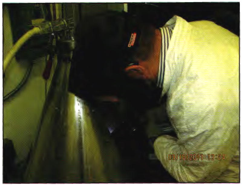
The basic welding system included a multiprocess welding machine (an MP350 from The Lincoln Electric Co., Cleveland, Ohio) with a wire feeder capable of rates to 300 in./min (762 cm/min). Welding was conducted in a conical chamber based on an American Welding Society (AWS) design for a chamber to measure fume-generation rates (Ref. 7). A photograph of the chamber in operation is shown in Fig. 1. The test chamber was validated to AWS performance standards and met the performance criteria. Aerosols were drawn from the chamber with a pump at 200 L/min. The approximate chamber aerosol concentration was monitored with a DataRAM 4000 (Thermo Electron, Franklin, Mass.). Stainless steel welding wire was AWS A5.9 Class ER308LSi 0.045 in. (1.14 mm) in diameter, fed from an 11.4-kg (25-lb) reel. The GMAW samples analyzed for Cr6+ in this study were sampled from a single lot of wire. The manufacturer’s nominal composition of the wire is 2% Mn, 19–25% Cr, 10–13% Ni, and the remainder Fe. Flux cored arc welding used AWS A5.22 Class E308LT0-1 wire, while SMAW generation used AWS A5.4 Class E308L-16 -in. (4.8-mm) rods.
Fig. 1.
American Welding Society-type welding chamber in use.
Shielding gas was taken from pressure-regulated cylinders at a flow rate of 19 L/min. The welding material in the baseplates was ½-in.- (12.7-mm-) thick 304 stainless steel, 22-in.- (56-cm-) diameter disks. Operation with all shielding gases and welding process types used similar conditions, but was adapted to good welding practice, generally as recommended by welding machine manufacturers. All welding operations were adjusted for good bead appearance with good penetration of the base plates and good toe wetting and without undercut. Baseplates were rotated at the desired rotary speed to provide a travel rate compatible with good welds. A commercial welding turntable was modified for external control by the Labview (National Instruments, Austin, Tex.) program; rotary speed was detected by an encoder on the output shaft and input to the program, and the travel rate displayed continuously during operation. Welding machine operation was initiated under program control to precisely control arc time.
Operating variables are shown in Table 1.
Table 1.
Operating Variables for Generated Welding Fume Samples
| Shielding Gas | Gas Flow | Weld Mode | Wire Feed cm/min | Voltage (V) | Current (A) |
|---|---|---|---|---|---|
| Ar/CO2 99%/1% | 19 L/min | Short circuit | 320 | 17–18 | 120 |
| Ar/O2 99%/1% | 19 L/min | Short circuit | 320 | 17–18 | 125 |
| He/Ar/CO2 90%/7.5%/2.5% | 19 L/min | Short circuit | 320 | 19.5 | 100 |
| Ar/CO2 99%/1% | 19 L/min | Axial spray | 760 | 25 | 200 |
| Ar/O2 99%/1% | 19 L/min | Axial spray | 760 | 23 | 200 |
| Ar/O2 98%/2% | 19 L/min | Pulsed spray | 760 | 0.9 V trim | (pulsed) |
| Ar/CO2 75%/25% | 19 L/min | FCAW | 760 | 26 | 160 |
| none | none | SMAW | 361(a) | ~20 | 150 |
Equivalent wire feed speed based on an equal mass consumption rate.
Sampling Strategies
Fumes from the weld area were sampled through a 102-mm filter at the top of the chamber at 200 L/min. The filter material was Hollingsworth and Vose (East Walpole, Mass.) electrostatic medium (PE 13060NA), cut to fit the filter housing. The flow was measured with a mass flow meter (TSI, Shoreview, Minn.) before sampling. After sampling was completed, filters were removed from the housing, folded inward, weighed to the nearest 0.1 mg, and put in sealed antistatic polyethylene bags.
Sample Recovery and Processing
Welding fume particulate matter was recovered from the filters by gentle suction onto a 47-mm, 0.8-μm polycarbonate filter. The 47-mm stainless steel filter housing had a short piece of 6-mm ID silicone tubing, cut at 45 deg on the inlet end, and a house vacuum was connected to the outlet end. Using a gentle blotting action, most of the particulate fume was removed from the filter. Sufficient quantity was collected for analysis of Cr6+ and other metals, but quantitative recovery was not necessary. After completion, the polycarbonate filter was removed from the housing over a tared 75 × 75-mm weighing boat, and material brushed from the filter and housing interior with a #3 artist’s brush. The fume was treated with an antistatic device at this point to prevent losses. The dust was then ground in a metal-free apparatus to homogenize the sample for replicate analyses. Preliminary results indicated large differences between replicate samples weighed from material recovered from filters and subsequently analyzed, with coefficients of variation typically >20% for replicate samples. The process below resulted in much better precision for replicate samples, with coefficients of variation of typically 5–10%. The system used was a disposable 13-mm-diameter × 25-mm-long polyethylene vial with two 3.2-mm (⅛-in.) silicon nitride coated ceramic balls, shaken for 30 s in a Wig-L-Bug grinder. After grinding, the material was antistatic treated again, and weighed into 20-mL scintillation vials with PTFE-lined caps. Storage in the vials was at room temperature, in air, and vials remained sealed unless samples were removed for analysis. A previous study (Ref. 8) indicated samples were stable after three-months’ storage using this procedure. For Cr6+ analysis, 5.0-mg samples were weighed into 15-mL polycarbonate centrifuge tubes.
Field Study
The controlled comparison study was done in a large welding shop using bead-on-plate welding on 0.25-in. 309 stainless steel in the flat position, to maximize exposures. Welding was kept at 50% arc time for all processes tested, which included SMAW, FCAW, and GMAW (short-circuit, spray, and pulsed spray modes). There were 8 observations for SMAW, 16 for FCAW, 6 for GMAW-SC, 8 for GMAW-spray, and 7 for GMAW-pulsed spray modes. All welders did each type of welding in the study. Samples were collected inside the welding helmets, and the welders wore half-face respirators with P100 filters during welding. Short-term trials were conducted to maintain 8-h time-weighted average exposure levels below the OSHA Cr6+ permissible exposure level (PEL).
Analysis for Cr6+
Samples were treated and analyzed using NIOSH Physical and Chemical Analysis Method 7605, Hexavalent Chromium by Ion Chromatography (Ref. 9). The estimated limit of detection is 0.02 μg, and the method range is 0.05 to 20 μg of Cr6+. Five mL of extraction solution (3% Na2CO3/2% NaOH) were added to each 5-mg sample, and the tubes sonicated in a bath for 30 min. This procedure extracts both soluble and insoluble Cr6+ present in the fumes. Samples were removed and centrifuged for 15 min at 3500 × g. The supernatant was transferred to 25-mL volumetric flask and diluted with H2O. Samples were analyzed by ion chromatography using a Dionex HPIC-AS7 column with 250 mM (NH4)2SO4/100 mM NH4OH mobile phase and a postcolumn reagent (2.0 mM diphenylcarbazide/10% methanol/1N H2SO4) with absorbance detection at 540 nm. Four concentrations of standards were made from a certified Cr6+ solution, covering a range of 0.4–4 μg/mL.
Particle Size Distributions
Particle size distributions of different welding fumes were determined by using two Micro-Orifice Uniform Deposit Impactors (MOUDI and Nano-MOUDI, MSP Models 110 and 115; MSP Corp., Shoreview, Minn.). By combining the two impactors, the particles were size-classified and collected into 15 fractions ranging from more than 18 μm down to 10 nm. Besides the special feature of being able to classify nano-size particles, the MOUDI has rotating stages to obtain a nearly uniform particle deposit on the collection substrates, which reduces particle bounce and improves subsequent analysis. The total flow rate for the impactors was 30 L/min, and they were operated for 4 min total sampling time.
Statistical Approaches
The data did not follow a normal distribution, and were extremely skewed. Therefore, the Kruskal-Wallis nonparametric test was used to look for statistically significant differences between groups. Statistical results were considered significant at a p-value of 0.05.
Results
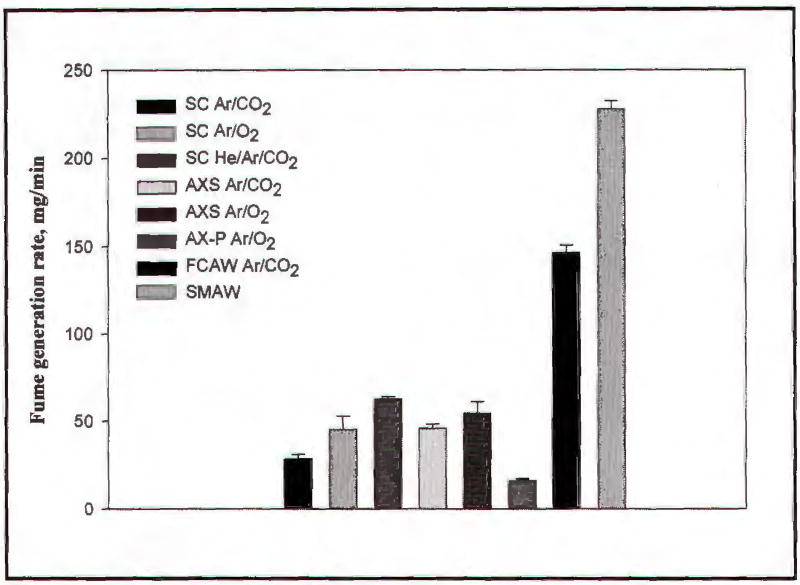
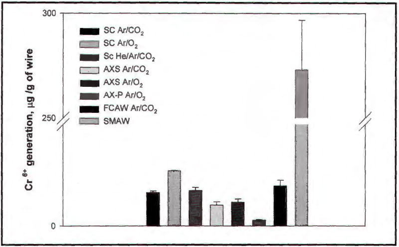
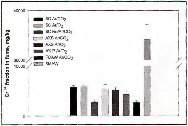
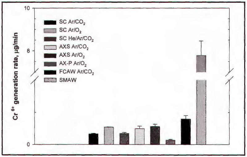
Fume-generation rates for four runs are displayed graphically in Fig. 2. The results in Figs. 2–5 are presented as arithmetic means ± standard error of the mean. Results range from 16 mg/min (GMAW-P) to 228 mg/min (SMAW). The Cr6+ fractions in the fume, in mg/kg (ppm) are displayed in Fig. 3. The results are the arithmetic means ± standard error of three replicate samples for each of the four welding runs. Results range from 2800 ppm (GMAW-S using He/Ar/CO2 shielding gas) to 34000 (SMAW). The Cr6+ generation rates were calculated as the product of the fume-generation rate and the Cr6+ fraction in the fume, and are displayed in Fig. 4. Additionally, some of the differences in total fume-generation rate and Cr6+ generation rates were influenced by the different wire-feed rates necessary to maintain optimal welds. The normalized generation rate is related to a welder’s exposure for any given weld, since the weld is not complete until sufficient metal is deposited to meet the requirements of that weld. Therefore, the generation rates were renormalized with respect to wire feed rates; results are shown in Fig. 5. The results normalized for wire-feed rates were calculated as the product of the Cr6+ generation rate and the reciprocal of the wire-feed rate in g/min. The SMAW rod-consumption rate was converted to a wire feed rate by relating the masses consumed per unit time, after measuring the rod lengths and density. The GMAW-P results were significantly smaller than all other processes for fume-generation rate, Cr6+ generation rate, and Cr6+ generation rate per gram of wire, p< 0.0004, but not for Cr6+ composition in the fume (ppm).
Fig. 2.
Welding fume-generation rates for eight welding processes, in mg/min.
Fig. 5.
Hexavalent chromium generation rates for eight welding processes, in μg Cr6+/g of welding wire consumed.
Fig. 3.
Hexavalent chromium content in welding fumes from eight processes, in mg/kg.
Fig. 4.
Hexavalent chromium generation rates for eight welding processes, in μg Cr6+/min.
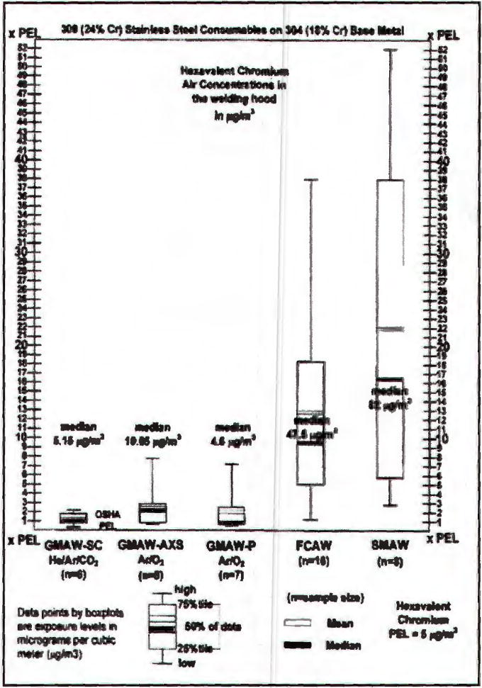
The results of the field-controlled comparison study in a welding shop are shown in Fig. 6. The results are shown as box plots of the observed exposure concentrations in μg/m3, with the median identified and the box spanning the 25th to 75th percentile, and the whiskers encompassing the entire range of observations.
Fig. 6.
Hexavalent chromium exposures inside welder’s helmets in μg Cr6+/m3 for five welding processes.
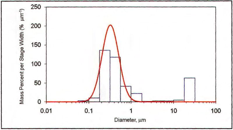
A typical particle size distribution is shown in Fig. 7, including the curve for the best-fit unimodal model. All of the processes also included substantial mass in the large, nonrespirable fractions >10 μm, most likely associated with microspatter from the welding processes. Summary data on geometric mean particle sizes and respective geometric standard deviations are shown in Table 2.
Fig. 7.
Particle size distribution of a typical welding fume in this study using a MOUDI device.
Table 2.
Mass Median Aerodynamic Diameters (MMADs) and Geometric Standard Deviations (GSDs) of Welding Fumes for Different Shielding Gases and Processes, from MOUDI Data
| Shielding Gas | Process | MMAD (nm) | GSD |
|---|---|---|---|
| Ar/CO2 99%/1% | Short circuit | 340 | 1.46 |
| Ar/O2 99%/1% | Short circuit | 280 | 1.53 |
| He/Ar/CO2 90%/7.5%/2.5% | Short circuit | 330 | 1.47 |
| Ar/CO2 99%/1% | Axial spray | 260 | 1.23 |
| Ar/O2 99%/1% | Axial spray | 250 | 1.37 |
| Ar/CO2 98%/2% | Pulsed spray | 320 | 1.58 |
| Ar/CO2 75%/25% | FCAW | 363 | 1.35 |
| — | SMAW | 600 | 1.34 |
Discussion
The results showed a wide range of fume-generation rates (a 14:1 ratio overall, and 4:1 for GMAW), demonstrating there are clearly some best and worst choices for minimizing total fume exposures. The results were somewhat greater than those found in similar studies (Refs. 8, 10, 11). A probable explanation is that the chamber used in this study was highly efficient with low losses and a minimal residence time. Evidence for this includes the observation of very little loss of fume to the interior of the chamber (< 1% of the collected mass for a given run), and the presence of substantial masses of large (>10 μm and > 18 μm) fractions in the MOUDI sampler; these are easily lost by sedimentation in large systems with long residence times and extended sampling lines.
The Cr6+ fractions (mg/kg or ppm) in the fumes were comparable to those in previous studies (Refs. 8, 10, 11): 2300–34,000 ppm overall, and 2300–6100 ppm for GMAW processes. Hexavalent chromium generation rates were again elevated relative to earlier findings, which was consistent with the higher fume-generation rates of the current study. The Cr6+ generation rates did not necessarily correlate with the Cr6+ content of the fume, especially for the very low fume-generating processes such as GMAW-P.
The controlled comparison field study confirmed the laboratory findings in general, but the very wide range of exposure concentrations found suggests that factors other than generation of Cr6+ at the source are critically important in determining exposures. While all of the welders in the small group welded in the same shop on the same materials, the results indicate that a single observation for each process was dramatically higher than the remaining exposures, for both GMAW-spray and GMAW-P modes. There was no obvious explanation for these anomalies, but some factor of work practice is probably responsible.
There have been a number of successful approaches to reducing Cr6+ in welding, including altered fluxes for SMAW and FCAW (Refs. 12, 13), secondary shielding gases for GMAW (Ref. 14), non-Cr-containing welding alloy wires and rods (Ref. 15), and chemical fume reactants (Ref. 16). This study concentrated on reducing generation of Cr6+ at the process level, and could be used along with some of those other methods, such as Cr-free welding wire, fume reactants, and a secondary shielding gas.
The various welding processes have multiple associated cost factors that are an important issue in selecting a welding process. Costs that need to be considered include consumables (welding wire, rods, shielding gases, etc.), equipment costs, and labor costs per completed weld.
Table 3 presents relative costs in a non-quantitative way, based on consumables costs from typical industrial suppliers, and manufacturers’ suggested prices on welding equipment that have similar current capacities, but different process capabilities. Comparisons in equipment costs are at best imperfect, and some process capabilities are available only in dedicated units, while others can be added to existing units.
Table 3.
Relative Cost Ratios for Stainless Steel Welding
| Shielding Gas | Weld Mode | Wire Costs | Equip. Costs | Gas Costs | Labor/Weld |
|---|---|---|---|---|---|
| Ar/CO2 99%/1% | Short circuit | + | ++ | + | ++ |
| Ar/CO2 99%/1% | Short circuit | + | ++ | + | ++ |
| He/Ar/CO2 | Short circuit | + | ++ | ++ | ++ |
| Ar/CO2 99%/1% | Axial spray | + | ++ | + | + |
| Ar/O2 99%/1% | Axial spray | + | ++ | + | + |
| Ar/O2 98%/2% | Pulsed spray | + | +++ | + | + |
| Ar/CO2 75%/25% | FCAW | ++ | ++ | ++ | + |
| none | SMAW | ++ | + | none | ++ |
In general, most welders will not be eager to change welding practices, especially for familiar tasks. Most welders are very skilled and confident in their abilities, and have completed training and certification testing for multiple types of welding. They know very well what works and how to solve problems, while this may not be the case for GMAW-P and other GMAW processes. Additionally, the work sequence is different when changing from SMAW to any of the GMAW techniques. For example, a typical SMAW sequence would be to prepare the area for welding, weld until the rod is consumed, put down the electrode holder (stinger) and go back and chip off the slag from the weld, inspect the weld and prepare any suspect areas for rewelding. Then, typically, they would mount a new rod and repeat the sequence. Gas metal arc welding work patterns would typically include preparation and then welding continuously as long as the torch cable can reach, unless obstacles, etc., are present. This may result in more fatigue, especially for vertical and overhead positions. Some training and testing may be necessary, but most GMAW processes, including GMAW-P, are not especially difficult to learn or use.
Some suggestions for easing adoption would be to replicate the timing intervals of current practice and keep welding rates (time for completion of a typical weld) similar at the outset, even though GMAW processes are often easier and faster than SMAW.
Recommendations
For fume-generation rate, Cr6+ generation rate, and Cr6+ generation rate per unit of wire in this study, pulsed spray GMAW was clearly the best of the processes evaluated. A previous study in multiple industrial plants (farm machinery manufacturing) confirms the clearly lower fume exposures in those facilities (Ref. 17) when using pulsed spray welding. The method has multiple practical advantages in addition to the minimal Cr6+ and total fume-generation rates: It is usable in any position, has low heat input that minimizes warping, the high metal deposition rate lowers labor costs, it is relatively simple to learn and use, it has a noncritical working distance and good visibility, and is only modestly more expensive than GMA welding machines with similar capacities. While there will be situations where pulsed spray mode may not be suitable, it would be a good choice in many applications, especially where Cr6+ exposures may be difficult to reduce by local exhaust ventilation or similar measures.
Footnotes
Disclaimer
The findings and conclusions in this paper are those of the author and do not necessarily represent the views of the National Institute for Occupational Safety and Health. The mention of any company names or products does not imply an endorsement by NIOSH or the Centers for Disease Control and Prevention, nor does it imply that alternative products are unavailable, or unable to be substituted after appropriate evaluation.
Contributor Information
M. KEANE, Email: mjk3@cdc.gov, National Institute for Occupational Safety and Health (NIOSH), Health Effects Laboratory Div., Morgantown, W.Va.
A. SIERT, Xcel Energy, Denver, Colo
S. STONE, National Institute for Occupational Safety and Health (NIOSH), Health Effects Laboratory Div., Morgantown, W.Va
B. CHEN, National Institute for Occupational Safety and Health (NIOSH), Health Effects Laboratory Div., Morgantown, W.Va
J. SLAVEN, NIOSH and Indiana University, Indianapolis, Ind
A. CUMPSTON, National Institute for Occupational Safety and Health (NIOSH), Health Effects Laboratory Div., Morgantown, W.Va
J. ANTONINI, National Institute for Occupational Safety and Health (NIOSH), Health Effects Laboratory Div., Morgantown, W.Va
References
- 1.Bureau of Labor Statistics, U.S. Department of Labor. Welding, soldering, and brazing workers. Occupational Outlook Handbook. 2006–07 [Online] at www.bls.gov/oco/ocos226.htm.
- 2.Antonini JM. Crit Rev Toxicology. 2003;33(1):61–103. doi: 10.1080/713611032. [DOI] [PubMed] [Google Scholar]
- 3.IARC. Monographs on the evaluation of carcinogenic risks to humans, Volume 49: Chromium, nickel, and welding. Lyon, France: 1990. [PMC free article] [PubMed] [Google Scholar]
- 4.NIOSH. Pocket Guide to Chemical Hazards. 2005. (DHHS (NIOSH) Publication 2005-149). [Google Scholar]
- 5.U.S. Environmental Protection Agency. Chapter 12: Metallurgical Industry. AP 42, Section 12.19: Development of Particulate and Hazardous Emission Factors for Electric Arc welding. [Online] at www.epa.gov/ttn/chief/ap42/index.html.
- 6.NIOSH. Criteria for a Recommended Standard: Welding, Brazing, and Thermal Cutting. Cincinnati, Ohio: 1988. (DHHS (NIOSH) Publication No. 88-110). or available at www.cdc.gov/niosh/topics/hexchrom/ [Google Scholar]
- 7.AWS F1.2. Laboratory Method for Measuring Fume Generation Rates and Total Fume Emission of Welding and Allied Processes. Miami, Fla.: American Welding Society; 2006. [Google Scholar]
- 8.Keane M, Stone S, Chen B, Slaven J, Schwegler-Berry D, Antonini J. J Env Mon. 2009;11:418–424. doi: 10.1039/b814063d. [DOI] [PubMed] [Google Scholar]
- 9. (Method 7605, Hexavalent chromium by ion chromatography).NIOSH Analytical Methods Manual. (4th) available at www.cdc.gov/niosh/nmam/default.html.
- 10.Moreton J, Smars EA, Spiller KR. Metal Construction. 1985;17:794–798. [Google Scholar]
- 11.Yoon SY, Paik NW, Kim JH. Ann Occ Hyg. 2003;47:671–680. doi: 10.1093/annhyg/meg063. [DOI] [PubMed] [Google Scholar]
- 12.Dennis JH, French MJ, et al. Ann Occup Hyg. 2002;46(1):33–42. doi: 10.1093/annhyg/mef024. [DOI] [PubMed] [Google Scholar]
- 13.Kimura S, Kobayashi M, Godai T, Minato S. Welding Journal. 1979;58:195-s–203-s. [Google Scholar]
- 14.Dennis JH, French M, Hewitt P, Mortazavi S, Redding C. Ann Occ Hyg. 2002;46:43–48. doi: 10.1093/annhyg/mef019. [DOI] [PubMed] [Google Scholar]
- 15.Sowards JW, Liang D, Alexandrov BT, Frankel GS, Lippold JC. Welding Journal. 2011;90:63-s–76-s. [Google Scholar]
- 16.Topham N, Kalivoda M, Hsu CY, Oh S, Cho K. J Aerosol Sci. 2010;41:326–330. [Google Scholar]
- 17.Wallace M, Landon D, Song R, Echt A. Appl Occ Environ Hyg. 2001;16:93–97. doi: 10.1080/104732201460127. [DOI] [PubMed] [Google Scholar]


