Abstract
Three-dimensional (3D) guidance for endovascular procedures has developed over the last decade from 3D rotational angiography to the use of dynamic 3D roadmap techniques. The latest development is image merging. This technique combines real-time feedback of fluoroscopy with optimal soft-tissue contrast of previously performed computed tomography (CT) or magnetic resonance angiography. Merging of CT angiography and cone-beam CT/fluoroscopic images is feasible, and preliminary results look promising. Merging will allow us to further reduce radiation exposure, contrast dose, and procedural time, and its main use and benefit will be in complex endovascular interventions.
Keywords: 3D navigation, Cone-beam computed tomography, Endovascular, Fusion imaging
Introduction
Over the last decades, there has been a rapid evolution in three-dimensional (3D) guidance for endovascular procedures. Initially, 3D rotational angiography (3D-RA) became available, later followed by dynamic 3D roadmap techniques. 3D-RA increases diagnostic accuracy, and it can be used for the optimization of angulation and skew in the planning of procedures with complex anatomy. Dynamic 3D roadmapping is used mainly in the guidance of embolization (liver, uterus, etc.), and it facilitates more complex procedures. Real-time monitoring from any angle is possible, and this technique allows for change in magnification during a procedure without the need to perform a new angiographic series or roadmap. Typically, this technique uses a so-called “split screen” of live fluoroscopy and a 3D roadmap. With the use of flat-panel technology, cone-beam computed tomography (CT) has become available in the interventional suite. Cone-beam CT is an additional step toward higher accuracy, and this technique allows visualization of thrombus, calcification, and structures surrounding the arteries. The latest development in 3D guidance is image merging. This technique combines real-time feedback of fluoroscopy with the optimal soft-tissue contrast of CT angiography (CTA) or magnetic resonance angiography (MRA) performed during a diagnostic workup. The reuse of diagnostic CT/MR data can save contrast, time, and radiation for the patient and staff and incorporates large-volume imaging into the interventional suite. Tracking of the angiography table in combination with CT/MR offers a single roadmap from the groin to feet/head for different steps during a procedure. Merging can be performed using either cone-beam CT acquisition (3D-3D) in the angiography suite or fluoroscopy (2D-3D).
Background of 3D Navigational Techniques
Rotational Angiography and Cone-beam CT
In conventional rotational angiography, a motorized movement is performed at constant speed of the C-arc around the patient while contrast is infused with concomitant cinefluoroscopy. To obtain 3D images from a conventional rotational angiographic run, two methods can be used. The first consists of an examination in two phases, where at first the C-arm makes a sweep acquiring images that act as a mask for subsequent data acquisition. Subsequently, a return sweep is performed while contrast is injected throughout the entire period of data acquisition, and subtraction of both runs is performed [1,2]. The second method is based directly on conventional rotational angiographic images without the use of subtraction [3–5].
Using specific algorithms, the data set is reconstructed into a volume-rendered image. The 3D volume obtained in this way can be rotated and viewed in any direction, and optimal tube positioning (angulation, skew) can be chosen. Determination of vessel geometrical properties (length, diameter) can be done manually or using automated vessel analysis software. The use of 3D-RA (even when using the two-phase acquisition) does not lead to an increase in radiation dose delivered to the patient, and the effective radiation dose can even be reduced [2,5].
A disadvantage of the classical 3D-RA technique is non-visualization of thrombus. The same is true for conventional angiography. However, calcifications can be demonstrated with 3D-RA using either the source images showing indirect signs of the presence of a thrombus (discrepancy between angiographic lumen and location of calcification) or calcified plaque software. Recent software developments and flat-panel detectors allow for so-called soft-tissue imaging, which yields images similar to those obtained by CT. In fact, the rotating X-ray tube and flat-panel detector can be considered to be a CT scanner. This technique of so-called cone-beam CT (available under the commercial names XperCT, DynaCT, and Innova CT) uses a wider beam of X-rays compared with the classical (multidetector) CT scanners, in combination with all the individual detectors of the flat-panel detector. For this reason, a higher spatial resolution can be obtained (28 line pairs/cm for cone-beam CT compared with 16 line pairs/cm for CT). A cone-beam CT protocol consists of 621 projections of 1024 × 792 pixels at the 30 × 40-cm zoom format (0.370-mm pixel pitch). The images are acquired at 30 frames/s in 20.7 s. A low-dose protocol acquiring 312 images in ∼5 s is also available. A disadvantage of the cone-beam CT technique is the lower contrast resolution and an increased susceptibility to beam-hardening artifacts and noise (as an X-ray beam passes through an object, it becomes “harder,” i.e. its mean energy increases because the lower energy photons are absorbed more rapidly than the higher energy photons; this hardening leads to artifacts characterized by [dark] bands and streaks).
The volume obtained with cone-beam CT can also be used to guide needle-assisted procedures (XperGuide Philips Medical Systems, Best, The Netherlands; syngo iGuide Siemens, Erlangen, Germany). This navigational tool creates an overlay of live fluoroscopy and 3D soft-tissue imaging that provides information on the planned needle path from entry point to target [6]. Changes to live fluoroscopy following an adjustment of the X-ray/detector distance, position, and/or magnification are transferred to the 3D reconstruction so that the matching is maintained throughout the procedure. Guidance graphics are superimposed onto the fluoroscopic data, and it is possible to superimpose the graphics onto slice data or volume data, thus achieving a better understanding of the needle position with respect to the surrounding soft-tissue structures that are not visible on the fluoroscopic images.
Technical Considerations of Image Merging
High-quality imaging and precise navigation guidance are two prerequisites for the successful execution of endovascular procedures. Most physicians still rely on 2D fluoroscopic imaging alone for complex cases, even though a 3D perspective of the vasculature is desirable for catheter navigation and positioning of devices. Hence, it would be desirable to have a means to combine the data from several imaging systems to deliver the missing information during preparation of the procedure and the interventional treatment itself. To successfully overlay a preoperative CT or MR on live fluoroscopy (a process called merging or image fusion), the volume needs to be aligned or “registered” with the patient on the angiography table. This means that, after registration, all relevant structures of the preoperative scan coincide with the structures as seen on live fluoroscopy, irrespective of the chosen angulation or rotation of the C-arm or changes in table position. Merging can be performed using two types of alignment: 2D-3D and 3D-3D registration.
One such tool is the VesselNavigator (Philips Healthcare, Best, The Netherlands). The VesselNavigator overcomes the missing 3D perspective and adds the information from the third dimension by combining previously acquired CT data sets and real-time fluoroscopic imaging. The CT data set provides an accurate 3D model of the region of interest through segmentation and identification of key anatomical structures of the vessel tree. During the procedure, the VesselNavigator software overlays the 3D computed tomography angiography (CTA) volume on live fluoroscopy using alpha blending. The VesselNavigator workup comprises four steps.
Step 1: Segmentation
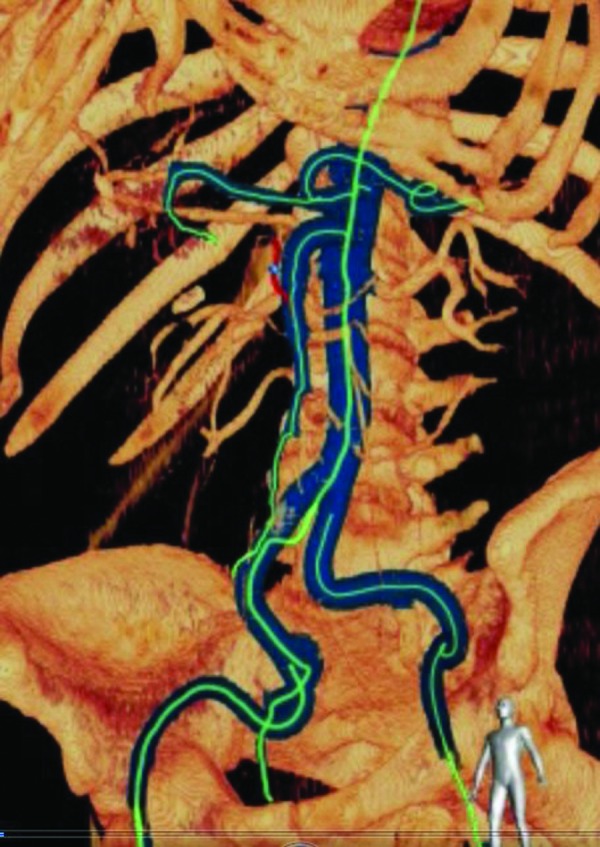
The CT data set is imported into a dedicated 3D workstation. By means of a semiautomatic segmentation algorithm, the vasculature of interest is separated from bones and soft tissue in CTA. The system uses an optimized fast-marching algorithm to trace the vessels through the volume and tags voxels that match vessel identification criteria. Using these tags, the system can set specific colorization and translucency of the vessels (Fig. 1). This enables a plain view of the vasculature of interest, without the potential interference from overlapping vessels and bones (e.g. pelvis, spine, ribcage). This facilitates both procedural planning and subsequent intraprocedural navigation.
Figure 1.

Planning phase: semiautomated vessel identification of computed tomography angiography volume. Arteries of interest are depicted in blue.
Step 2: Planning
In the planning step, the user can interact with the (segmented) CTA to find optimal working projections to be used during the intervention. The projection angles can be stored and later recalled to automatically steer the C-arm to the predefined rotation/angulation. Furthermore, during this step, the user can perform measurements and highlight important anatomical features by placing landmarks that will be visible during live guidance on the overlay image.
Step 3: Registration
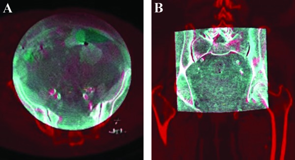
Cone-beam CT (3D-3D registration) makes use of an intraprocedural rotational scan, either cone-beam CT (without injection of iodinated contrast, giving CT-like soft-tissue contrast resolution) or 3D-RA (with contrast injection, visualizing high-contrast structures such as bone, calcifications, and contrast-filled vessels). The intraprocedural scan is done with the patient on the table in the position that is needed for the procedure. Because the position and movement of the C-arc are tracked, the position of the region of interest in the patient, as seen in the resulting volume, is fully known. In the next phase, the pre-acquired CTA or MRA volume is fused with the intraoperative cone-beam CT based on anatomical landmarks visible in both 3D scans (Fig. 2). Landmarks of interest are manually identified in a side-by-side view, landmarked, and subsequently paired. At least three landmark pairs are needed. To obtain a high accuracy of the overlay, calcifications of the vessels can be chosen as landmarks.
Figure 2.

3D-3D registration in axial (A) and coronal (B) planes. The cone-beam computed tomography (CT; gray) is superimposed on the CT angiography reconstruction (red). Note the matching of bony structures and arterial calcifications.
In fluoroscopy (two different angles), the registration step ensures that the fluoroscopy stream can be accurately superimposed on the 3D volume of the CTA. To register the orientation of the CTA to the coordinate space of the C-arm, the user acquires X-ray images (short fluoroscopy runs or single frames) from two different projection angles, with a delta of at least 20° (in practice, a delta of >40° is used). Anatomical features from the two X-ray runs (predominantly bone structures) are matched with the corresponding features on the CTA. The system takes into account the inverse-perspective nature of X-ray and allows for registration along normal axes, even when the delta angle is <90°. Once this is complete, the fluoroscopy stream is accurately overlaid on the CTA, regardless of C-arm and table positioning. The registration can be performed by the physician at tableside using a touch screen with a sterile cover.
The radiation dose can be considerably reduced by using fluoroscopy for the registration step. To estimate the difference in effective dose between cone-beam CT and two oblique fluoroscopy projections for the purpose of registering the CTA with live fluoroscopy in an anthropomorphic mathematical phantom, a Monte Carlo modeling software package (PCXMC, STUK, Helsinki, Finland) was used. For this estimation, a patient of 175 cm in height was assumed while varying the patient's weight between 60 and 90 kg. The abdominal aorta was assumed to be in the isocenter. Simulation of the cone-beam CT scan assumed the C-arm to be in propeller position and used a low-dose protocol especially designed for the purpose of registration of the cone-beam CT to a diagnostic CT or MR data set. For simulation of the two 3-s fluoroscopy projections, projection angles of +30° and −30° were modeled, and a dose rate of 2.5 röntgen/min (lowest dose setting; 1 röntgen is equivalent to 10 mSv) was used.
The results of the simulation indicate that registration using cone-beam CT yields an effective dose of 1.53-1.66 mSv, whereas registration using two oblique fluoroscopy projections results in an effective dose of only 0.14-0.20 mSv. In perspective, a 6-s digital subtraction angiography run with 3 frames/s gives an effective dose of 0.91-1.46 mSv.
An additional advantage of the fluoroscopy registration is that it can be performed by the operator in a sterile fashion, with the patient already draped. Cone-beam CT registration is typically performed before draping, and therefore, care should be taken that the patient does not move while being draped, as this would lead to misregistration (see below).
Step 4: Live Guidance
During live guidance, the VesselNavigator shows an overlay image of the CTA and live fluoroscopy stream. The CTA is projected in the inverse-perspective space of the X-ray beam and thus provides a visual roadmap to direct the catheter during intraprocedural navigation. The roadmap is synchronized, in real-time, with changes in rotation, angulation, and lateral movements of the C-arm, as well as with the table position, detector height, and magnification. According to user preference, the roadmap is displayed either as an outline or a volume surface rendering of the segmented vessels, optionally with interpolation-based surface shading. When additional orientation is required, the volume rendering of the vessels can be combined with a semitransparent rendering of the soft tissue and bony structures. If needed, small adjustments in the registration can be made by translating or rotating the CTA or MRA volume with respect to the intraoperative scan.
Steps 1 and 2 can be done at the physician's convenience before the procedure. Steps 3 and 4 are carried out in the angiography suite, with the patient on the table.
Clinical Applications and Review of the Literature
Merging combines real-time feedback of fluoroscopy with optimal soft-tissue contrast of CT/MR. The technique of fusion imaging can be used in almost all endovascular procedures, but its main benefit will be in complex interventions that require multiple changes in the position of the C-arm with respect to the length axis of the patient and in procedures that require changes in angulation and skew during the various steps of a procedure. Previously acquired CTA data can provide the required information not only for planning but also for guiding the endovascular procedure [7]. Merging brings large-volume imaging into the angiography suite. Tracking of the table in combination with CT can therefore offer a single roadmap from the groin to feet/head for different steps during a procedure.
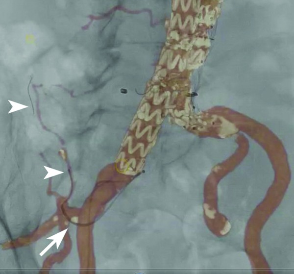
This technique will reduce the amount of contrast medium used, and selective catheterization of side branches can even be performed without using any contrast [8]. In a series of 20 uterine artery embolization procedures, Gupta and Grunhagen [9] reported an accurate overlay in all cases. In 85% of cases, the uterine artery was successfully catheterized with no iodinated contrast medium at all by relying solely on the MRA roadmap. Given the high prevalence of renal insufficiency in patients undergoing endovascular procedures and its dependence on nephrotoxic contrast injections, the ability to minimize contrast load will confer a benefit to patients [10]. A good example is the treatment of type II endoleaks after endovascular aortic repair (EVAR) or cases of superselective (chemo)embolization. In these cases, usually multiple-vessel bifurcations need to be crossed, with each bifurcation requiring a different angulation of the X-ray tube for efficient navigation (Fig. 3).
Figure 3.

Image demonstrating merging of fluoroscopy and computed tomography angiography during transcatheter embolization of a type II endoleak. A diagnostic catheter is positioned in the common trunk of the right hypogastric artery (arrow). A microcatheter and guide wire can be seen in the right iliolumbar artery (arrowheads).
The technique has also been applied successfully in emergency embolization of patients with visceral or trauma-related hemorrhage. Other applications include carotid stenting, thoracic EVAR, EVAR, and fenestrated/branched endografting.
Much of the complexity of these procedures is related to the anatomy of the supra-aortic and visceral branches and the consequent challenges in accurate navigation. Each of the main side branches typically lies in a different anatomical plane, and fluoroscopic imaging superimposes the devices into a 2D image, making interpretation of the relative positions in the third dimension more difficult. Therefore, in cases in which 2D imaging is used as a single modality, frequent control imaging in multiple planes is necessary, which leads to prolonged procedural times and increased radiation exposure for the patient and operator [11]. The use of 3D navigation with image merging reduces the need for multiple (3D) roadmaps: the use of a CT roadmap allows straightforward interpretation through direct coupling with fluoroscopy and makes it possible to select optimal working angles throughout the procedure on the basis of the 3D diagnostic CTA.
A study that compared a historical cohort with a group of patients treated with perioperative guidance of fenestrated EVAR by fusion of preoperative cone-beam CT with multidetector CT showed a statistically significant reduction in contrast dose (94 versus 136 mL) [12]. In this study, there was a trend toward lower operative times (330 versus 387 min) and fluoroscopy times (81 versus 90 min); however, this difference did not reach statistical significance.
Similar results were reported by another group who evaluated fenestrated and branched endografts [13]. Iodinated contrast material volume and procedural time were significantly lower in the fusion group than in case controls (159 versus 199 mL and 5.2 versus 6.3 h, respectively). No significant difference in fluoroscopy time between the two groups was observed.
Another study compared three intraprocedural image guidance methods: 2D angiography, 3D-RA, and image fusion [14]. X-ray exposure (dose-area product), injected contrast medium volume, and procedural time were recorded. There was no statistical difference in endograft deployment success among the three groups. The duration of the procedure did not differ among the three groups. The image fusion group showed a significant reduction in injected contrast medium volume compared with the other groups (mean volume: 2D, 235 mL; 3D, 225 mL; image fusion, 65 mL). Mean dose-area product values showed no significant difference among groups, although there was a trend toward reduction in the image fusion group (2D, 1,188 ± 1,067 Gy/cm2; 3D, 984 ± 581 Gy/cm2; image fusion, 655 ± 457 Gy/cm2; P = 0.18). The X-ray exposure of a cone-beam CT scan as used in the latter study varies with the angiographic system, but remains lower than that of a conventional multidetector CT scan. To put this into perspective, the estimated dose absorbed after a cone-beam CT scan in a porcine animal model was as high as 0.77 mSv [15]. In the study by Tacher et al [14], the mean dose-area product at the end of the intervention was reduced in the image fusion group even though cone-beam CT was used (using 2D-3D merging potentially reduces the radiation exposure further). It has been demonstrated in the animal model that the use of merging techniques can improve technical success rates in complex recanalization procedures while reducing fluoroscopy time as well [16].
Potential pitfalls are inappropriate matching of CT volume and fluoroscopy, leading to misregistration. Respiration-related and cardiac cycle-related vessel displacement, vessel elongation, and displacement by stiff devices and patient movement have been identified as reasons for fusion image inaccuracy [13]. The insertion of rigid (stent) delivery systems into the vascular system can significantly alter the anatomical relations due to “stretching out” of the vessels. The devices will generally “cut corners.” This can result in clinically significant errors for any technique that relies on a rigid image registration of a preoperative anatomy. The margin of error caused by misregistration is more pronounced in tortuous arterial segments and is minimal in relatively straightforward anatomy [11].
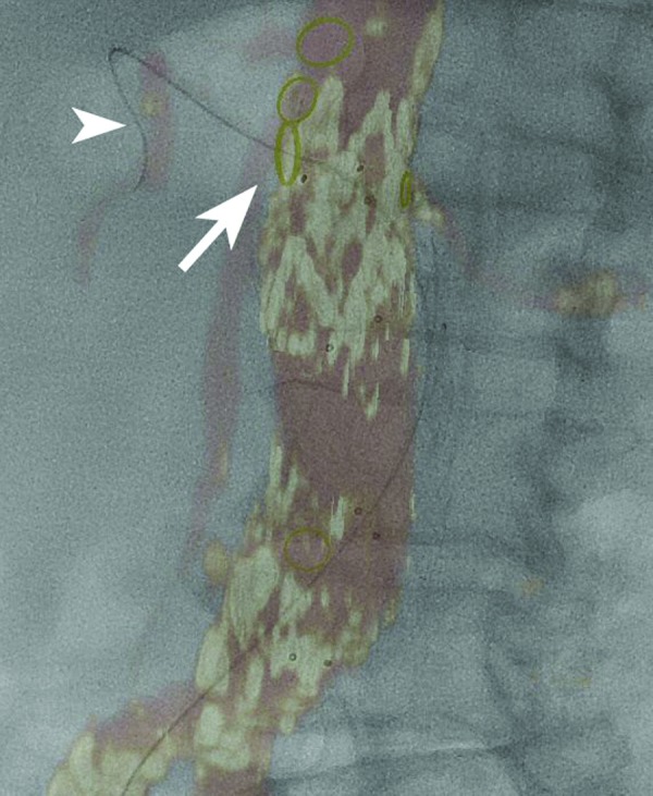
Movement caused by the cardiac and respiratory cycles usually is not a source of significant errors in the position of the renal artery ostia. Although the kidney itself may move significantly with respiration, there is little movement of the renal ostia (Fig. 4) [11]. This also applies to other visceral artery branches. Software algorithms that allow for correction of misregistration due to respiration and device rigidity are under development. Finally, it is important when using merging techniques to always check proper (and intraluminal) position of the delivery system/device before its deployment.
Figure 4.

Merged image after an endovascular aortic repair procedure. The origin of the right renal artery is indicated by a yellow oval (arrow). A guide wire can be seen in the right renal artery (arrowhead). Distally, a discrepancy in the position of the guide wire and the CTA overlay can be seen, related to respiratory movement. Note the absence of movement at the level of the renal ostium.
Conclusions
Merging of CTA and cone-beam CT/fluoroscopic images is feasible, and preliminary results look promising. The reuse of diagnostic CT data can reduce the amount of contrast medium used and reduce the procedural time and radiation exposure for the patient and staff. Its main use and benefit will be in complex endovascular interventions.
Conflict of Interest
The author has no conflict of interest relevant to this publication.
Footnotes
Based on a Presentation at the 2013 VEITH Symposium, November 19–23, 2013 (New York, NY, USA)
References
- 1. Unno N, Mitsuoka H, Takei Y, Igarashi T, Uchiyama T, Yamamoto N, et al. Virtual angioscopy using 3-dimensional rotational digital subtraction angiography for endovascular assessment. J Endovasc Ther. 2002;9:529–34. [DOI] [PubMed] [Google Scholar]
- 2. Klucznik RP. Current technology and clinical applications of three-dimensional angiography. Radiol Clin North Am. 2002;40:711–28. 10.1016/S0033-8389(02)00023-4 [DOI] [PubMed] [Google Scholar]
- 3. van den Berg JC, Overtoom TT, de Valois JC, Moll FL. Using three-dimensional rotational angiography for sizing of covered stents. AJR Am J Roentgenol. 2002;178:149–52. [DOI] [PubMed] [Google Scholar]
- 4. van den Berg JC, Moll FL. Three-dimensional rotational angiography in peripheral endovascular interventions. J Endovasc Ther. 2003;10:595–600. [DOI] [PubMed] [Google Scholar]
- 5. van den Berg JC. Three-dimensional rotational angiography. In: Wyatt MG and Watkinson AF. Endovascular intervention-current controversies. Shrewsbury, United Kingdom: TFM Publishing Limited; 2004, p. 247–56. [Google Scholar]
- 6. Braak SJ, van Strijen MJ, van LM, van Es HW, van Heesewijk JP. Real-time 3D fluoroscopy guidance during needle interventions: technique, accuracy, and feasibility. AJR Am J Roentgenol. 2010;194:W445–51. 10.2214/AJR.09.3647 [DOI] [PubMed] [Google Scholar]
- 7. Levitt MR, Ghodke BV, Cooke DL, Hallam DK, Kim LJ, Sekhar LN. Endovascular procedures with CTA and MRA roadmapping. J Neuroimaging. 2011;21:259–62. 10.1111/j.1552-6569.2010.00507.x [DOI] [PubMed] [Google Scholar]
- 8. Bargellini I, Turini F, Bozzi E, Lauretti D, Cicorelli A, Lunardi A, et al. Image fusion of preprocedural CTA with real-time fluoroscopy to guide proper hepatic artery catheterization during transarterial chemoembolization of hepatocellular carcinoma: a feasibility study. Cardiovasc Intervent Radiol. 2013;36:526–30. 10.1007/s00270-012-0495-9 [DOI] [PubMed] [Google Scholar]
- 9. Gupta A, Grunhagen T. Live MR angiographic roadmapping for uterine artery embolization: a feasibility study. J Vasc Interv Radiol. 2013;24:1690–7. 10.1016/j.jvir.2013.07.013 [DOI] [PubMed] [Google Scholar]
- 10. Kobeiter H, Nahum J, Becquemin JP. Zero-contrast thoracic endovascular aortic repair using image fusion. Circulation. 2011;124):e280–2. 10.1161/CIRCULATIONAHA.110.014118 [DOI] [PubMed] [Google Scholar]
- 11. Carrell TW, Modarai B, Brown JR, Penney GP. Feasibility and limitations of an automated 2D-3D rigid image registration system for complex endovascular aortic procedures. J Endovasc Ther. 2010;17:527–33. 10.1583/09-2987MR.1 [DOI] [PubMed] [Google Scholar]
- 12. Dijkstra ML, Eagleton MJ, Greenberg RK, Mastracci T, Hernandez A. Intraoperative C-arm cone-beam computed tomography in fenestrated/branched aortic endografting. J Vasc Surg. 2011;53:583–90. 10.1016/j.jvs.2010.09.039 [DOI] [PubMed] [Google Scholar]
- 13. Sailer AM, de Haan MW, Peppelenbosch AG, Jacobs MJ, Wildberger JE, Schurink GW. CTA with fluoroscopy image fusion guidance in endovascular complex aortic aneurysm repair. Eur J Vasc Endovasc Surg. 2014;47:349–56. 10.1016/j.ejvs.2013.12.022 [DOI] [PubMed] [Google Scholar]
- 14. Tacher V, Lin M, Desgranges P, Deux JF, Grunhagen T, Becquemin JP, et al. Image guidance for endovascular repair of complex aortic aneurysms: comparison of two-dimensional and three-dimensional angiography and image fusion. J Vasc Interv Radiol. 2013;24:1698–706. 10.1016/j.jvir.2013.07.016 [DOI] [PMC free article] [PubMed] [Google Scholar]
- 15. Loffroy R, Lin M, Yenokyan G, Rao PP, Bhagat N, Noordhoek N, et al. Intraprocedural C-arm dual-phase cone-beam CT: can it be used to predict short-term response to TACE with drug-eluting beads in patients with hepatocellular carcinoma? Radiology. 2013;266:636–48. 10.1148/radiol.12112316 [DOI] [PMC free article] [PubMed] [Google Scholar]
- 16. Klein AJ, Tomkowiak MT, Vigen KK, Hacker TA, Speidel MA, Vanlysel MS, et al. Multimodality image fusion to guide peripheral artery chronic total arterial occlusion recanalization in a swine carotid artery occlusion model: unblinding the interventionalist. Catheter Cardiovasc Interv. 20121;80:1090–8. 10.1002/ccd.24391 [DOI] [PMC free article] [PubMed] [Google Scholar]


