Abstract
We demonstrate acoustic tweezers used for disposable devices. Rather than forming an acoustic resonance, we locally transmitted standing surface acoustic waves into a removable, independent polydimethylsiloxane (PDMS)-glass hybridized microfluidic superstrate device for micromanipulation. By configuring and regulating the displacement nodes on a piezoelectric substrate, cells and particles were effectively patterned and transported into said superstrate, accordingly. With the label-free and contactless nature of acoustic waves, the presented technology could offer a simple, accurate, low-cost, biocompatible, and disposable method for applications in the fields of point-of-care diagnostics and fundamental biomedical studies.
Introduction
Manipulating micro-objects, such as cells and particles, is critical in fundamental biological studies, biomedical diagnostics and therapeutics.1–4 Micro-object manipulation can also play many key roles in the identification of common pathologies which plague developing countries. For example, separation and enrichment of immune cells or infected cells from a sample of whole blood or sputum has diagnostic implications for a plethora of diseases such as tuberculosis (TB) and asthma. Similarly extraction of particles from different reagents is needed in point-of-care identification of pathologies such as human immunodeficiency virus (HIV).5–7 Particularly, in the developing world, medical devices using cell/particle manipulation need to be simple, accurate, low-cost, disposable, and portable.7,8
Acoustic tweezers are an attractive approach to manipulate suspended micro-objects such as cells and microparticles using acoustic waves.9–11 Gentle mechanical vibrations, generated by acoustic transducers, induce a pressure field to move micro-objects in a contactless, label-free, and contamination-free manner. Recently, both bulk acoustic wave (BAW) and surface acoustic wave (SAW) based approaches have shown their prowess in the manipulation of macro- to nano- scale objects, regardless of an object’s optical or electrical properties.10,12–14 A wide range of applications in static or continuous flow such as manipulating cells, moving organisms, aligning protein crystals, and patterning nanomaterials have been demonstrated by either BAW or SAW tweezers.15–29 However, expanding the applications for acoustic tweezers is still limited by the complexity of device fabrication: a typical BAW-based microfluidic device is made of materials such as silicon and glass, which are challenging to implement with existing fast-prototyping methods, such as soft lithography. Although SAW microfluidics offer an attractive alternative by directly bonding polydimethylsiloxane (PDMS) microfluidic channels onto a piezoelectric substrate with interdigital transducers (IDTs)30–35, concerns still remain with the relatively high-cost and low-reusability of the piezoelectric substrate.
A superstrate, as defined here, is a disposable device which separates sample-handling units from excitation piezoelectric transducers, and will alleviate prior concerns for acoustic-wave-generating units. In a typical superstrate device, the traveling SAW is generated as an excitation source by a reusable SAW substrate, which usually is made with lithium niobate (a relatively expensive single piezoelectric crystal wafer). Then, this traveling wave transmits through a fluid-coupling layer and propagates toward a disposable superstrate. Devices with superstrates have been introduced into many diagnostic and analytical practices. For instance, droplet mixing, droplet rotating, and liquid pumping were achieved by coupling a superstrate such as a glass substrate, a silicon phononic crystal, or a microfluidic device.36–41 In addition, particle or cell trapping was accomplished in an SU8-glass composite microfluidic device from an acoustic resonance excited by a traveling SAW.42 However, dexterous cell/particle manipulation has yet to be demonstrated using a low-cost, simple, disposable superstrate device.
In this work, we developed reusable acoustic tweezers to realize acoustic manipulation of cells or particles with a SAW platform and disposable superstrate devices. A typical PDMS-glass microfluidic device was used as the superstrate, because plastic and polymer materials such as PDMS, polyethylene, or polycarbonate have been widely used to make disposable devices due to advantages including low cost, simple fabrication, and rapid prototyping.43 However, soft materials, such as PDMS, usually have a high acoustic attenuation coefficient, significantly absorbing the acoustic energy, which make it difficult to form an acoustic resonance.44,45 To address this, we replaced traveling SAWs with standing SAWs (SSAWs) as an excitation source. By locally transmitting SSAWs into the superstrate, cells or particles are manipulated in a disposable device. Our method relies on the regulation of displacement nodes in a piezoelectric substrate to conduct cell/particle manipulations. In comparison with the acoustic resonator approaches,42,46 our method can provide a more dexterous control of the acoustic field in the disposable device, which can be employed for all on-chip manipulations such as trapping, patterning, separating, sorting, and transporting. It offers a simple, low-cost, versatile, and disposable strategy for clinical diagnostics and fundamental biomedical studies.
Working mechanism
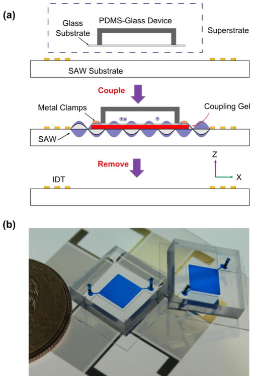
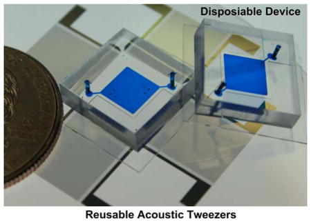
Fig. 1a illustrates the working mechanism of the reusable acoustic tweezers on a disposable superstrate device. The apparatus includes a SAW substrate and a disposable PDMS-glass device, which were assembled together with a thin layer of coupling gel (Fig. 1b). The SAW substrate is a lithium niobate (LiNbO3) piezoelectric material coated with a pair of paralleled interdigital transducers (IDTs) or two pairs of orthogonally arranged IDTs. One-dimensional or two-dimensional SSAWs can be generated by activating the SAW substrates. The SSAWs propagate on the surface of the substrate and introduce a distribution of pressure nodes between the IDTs. These SSAWs locally propagate into the top layer of coupling gel, and then transmit through the glass substrate entering the microfluidic chamber. Once the transmitted acoustic waves meet with liquid, a pressure field is formed in the PDMS-glass chamber. As a result, the cells and particles injected into the disposable device will be trapped to positions above the displacement nodes on the SAW substrate. After an acoustic manipulation experiment, the PDMS-glass device can be easily removed from the SAW substrate. Another disposable device can be subsequently assembled onto the same SAW substrate, which can be done by adding another drop of coupling gel without any need to clean the SAW substrate. In addition, cells and particles can be trapped and manipulated into different patterns or transported by regulating the configuration or the location of the displacement nodes on the SAW substrate.
Fig. 1.
Acoustic tweezers on a disposable device. (a) Schematic of our coupling method: A disposable microfluidic device can be coupled onto a SAW substrate with a thin layer of coupling gel. After an acoustic manipulation experiment, the disposable device can be removed, and the SAW substrate can be reused for another manipulation experiment. (b) Image of the disposable devices and the SAW substrate.
Methods
To fabricate a SAW substrate we first chose 128° YX-propagation LiNbO3 (500 μm thick, double-side polished) as the piezoelectric substrate. IDT fabrication followed the standard soft-lithography and lift-off technique. The LiNbO3 wafer was spin-coated with a 7 μm thick photoresist layer (SPR3012, MicroChem, USA). Then, the designed IDT patterns (40 electrode pairs with wavelengths of 150 μm, 200 μm, 300 μm, 400 μm, respectively) were transferred from the mask to the substrate by UV exposure and developed in a photoresist developer (MF CD-26, Microposit, USA). After depositing metal layers (Cr/50 Å, Au/600 Å) by e-beam evaporation (RC0021, Semicore, USA), IDTs were obtained with a lift-off process. To make a PDMS-glass device, a single-layer PDMS channel was created by standard SU8 soft-lithography. After drilling holes for an inlet and outlet with a puncher (0.6 mm diameter, Harris Uni-Core, USA), the molded PDMS was bound to a piece of cover glass (100 μm thick) by oxygen plasma treatment (PDC001, Harrick Plasma, USA). The superstrate-SAW substrate composite device was made by directly bonding the PDMS-glass hybridized microfluidic superstrate to SAW substrate with oxygen plasma treatment (PDC001, Harrick Plasma, USA).
The disposable PDMS-glass device was assembled on top of a SAW substrate with a layer of coupling gel, and fixed with metal clamps. The uncured UV epoxy (NOA 61, Edmund Optics Inc, USA) was chosen as the coupling material to introduce the acoustic waves from the substrate to the above device. In comparison with water or KY gel or other coupling materials, UV epoxy can offer a lower evaporation rate and a better coupling performance.
In the particle manipulation experiment, the device assembly was mounted on the stage of an inverted microscope (TE2000U, Nikon, USA). Solutions of 10 μm diameter polystyrene particles (Bangs liberates Inc, USA) were injected into the microfluidic chamber of the disposable device by a syringe pump (KDS210, KD Scientific, Germany) before turning on the acoustic field. Two independent radio frequency (RF) signals, generated by a double channel function generator (AFG3102C, Tektronix, USA), were amplified with two amplifiers (25A100A, Amplifier Research, USA). These signals were applied to IDTs individually in order to generate SSAWs and achieve phase control. The motion of particles were monitored or recorded with a CCD camera (CoolSNAP HQ2, Photometrics, USA). In the cell patterning experiment, a cooler plate (CP-31, TE Technology, USA) was used to control the temperature during SSAW exposure. Solutions of HeLa S3 cells (CCL-2.2, ATCC, USA) were injected and patterned in the same way as the particles. Images were acquired through an upright microscope (SMZ1500, Nikon, USA) with a CCD camera (DS-L2, Nikon, USA). The input voltages on the devices were 20~75 Vpp for manipulating polystyrene beads, and 40~50 Vpp for patterning HeLa S3 cells.
Results and discussion
Demonstration of SSAW coupling
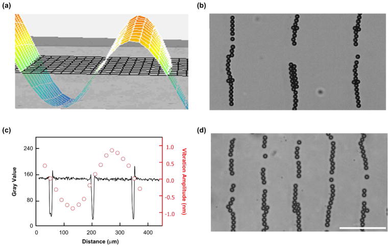
To develop a disposable device based on the acoustic tweezer platform, we introduced SSAWs into a superstrate containing a PDMS-glass microfluidic device. Before the coupling experiment, the distribution of displacement nodes on the SAW substrate were tested using a pair of parallel IDTs with a wavelength of 300 μm along the X axis of a 128° YX-propagation LiNbO3 substrate. Fig. 2a shows a two-dimensional map of the transversal vibration distribution after applying a RF signal (12.99 MHz, 34.5 Vpp) to the IDT pair. The cross section of the 2D map as a sine wave presents the transversal vibration amplitude distribution along the wave propagation direction. The peak (red) and trough (blue) of the sine wave indicate the displacement antinodes, while the stable points on the substrate (green) show the displacement nodes.
Fig. 2.
Characterization of local SSAW transmission. (a) 2D map of the transversal vibrations on the LiNbO3 substrate with a pair of parallel IDTs using a wavelength of 300 μm. The red and blue colors indicate the displacement antinodes on the substrate, and the green color indicates the displacement nodes. (b) 10 μm polystyrene particles were patterned into parallel lines with an interval distance of 150 μm by coupling 1D SSAWs with a wavelength of 300 μm. (c) The plot of spatial distribution of displacement node on the substrate (red circles) and particles patterning distribution in the disposable device (black curve) match with each other. The red circles show the distribution of the vibration amplitude, and the locations with a vibration amplitude of approximately zero indicate the displacement nodes on the substrate. The black curve indicates the location of patterned particles. (d) By using the same disposable device, 10 μm polystyrene particles were patterned into parallel lines with an interval distance of 75 μm by coupling 1D SSAWs with a wavelength of 150 μm. Scale bar: 100 μm.
Then, we employed the same SAW substrate for our coupling experiment. After assembling the disposable microfluidic device onto the SAW substrate, 10 μm polystyrene particles were injected into the microfluidic chamber. All the particles were driven and trapped into the parallel lines with an interval distance of 150 μm as the half-wavelength of the excitation wave when applying an excitation frequency of 12.99 MHz (Fig. 2b). We compared the spatial distribution of patterned particles (black curve) in the disposable device with the displacement nodes (red circles) on the SAW substrate (Fig. 2c), which match well. In addition, we coupled the same disposable device onto a SAW substrate with a pair of parallel IDTs using a wavelength of 150 μm. All the particles were similarly patterned in parallel lines with an interval distance of 75 μm in the disposable device, when applied a 23.33 MHz and 34.5 Vpp RF signal (Fig. 2d). By coupling the same disposable devices onto the SAW substrate with a wavelength of 200 μm or 400 μm, the particles were patterned into parallel lines with an interval distance of half-wavelength of the excitation waves, respectively. These patterning results at different excitation wavelengths indicate that the interval distance depends on the wavelength of the excited SSAW rather than the resonant frequency of the disposable device. Therefore, we can achieve dexterous manipulations by controlling the displacement nodes on the SAW substrate, regardless of chamber dimensions and channel materials.
Quantitative study of the reusable acoustic tweezers
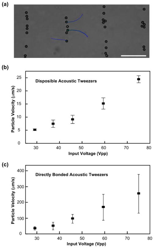
We further conducted experiments to quantitatively study our coupling method. In this experiment, we assembled a PDMS-glass device on a SAW substrate with a wavelength of 300 μm. 10 μm polystyrene particles were injected and randomly distributed into the microfluidic chamber. Then, we applied a RF signal with a frequency of 12.99 MHz and an input voltage of 50 Vpp to the IDTs. All the particles were patterned into parallel lines. During the process, the particles experienced an acoustic radiation force and a Stokes drag force, which drove the particles along the direction of wave propagation. The velocity of the particles reveals the acoustic radiation force. A video of the moving particles was recorded at this input voltage. The trajectory of single particles are shown in Fig. 3a, and the velocity of single particles were analyzed. Then, we applied RF signals with the same frequency under five different input voltages (29.1, 37.2, 45.8, 59.4, and 75.0 Vpp) after injecting new particles into the same device configuration each time. Each experiment under a given input voltage was repeated three times. The velocity of particles were measured and plotted in Fig. 3b.
Fig. 3.
Quantitative study of the reusable acoustic tweezers. (a) The particles were driven to a parallel line pattern via a coupled SSAW with particle trajectories shown by blue lines. (b)-(c) The velocity of particles in (b) a disposable acoustic tweezers device and (c) a directly bonded device were plotted under different input voltages (29.1, 37.2, 45.8, 59.4, and 75.0 Vpp). Scale bar: 100 μm.
In addition, we also performed the patterning experiment with a directly bonded acoustic tweezers device (PDMS layer is directly bonded to the piezoelectric substrate, without the glass substrate shown in Fig. 1a). This device contains the same PDMS chamber and SAW substrate as used with the superstrate technique, with a wavelength of 300 μm. When a 12.99 MHz signal was applied to the IDTs with five different input voltages (29.1, 37.2, 45.8, 59.4, and 75.0 Vpp), the velocities of the particles under different input voltages were obtained as shown in Fig. 3c. The velocity results indicate an 85% to 90% loss of the coupled device’s velocity when compared to the directly bonded device. However, the coupling method can provide a 10 μm polystyrene particle with an acoustic radiation force around several to tens of pN, which is large enough for many micromanipulation applications.
Moving a single particle using the reusable acoustic tweezers
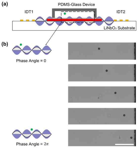
In order to transport cells or particles, we used a phase shift strategy to manipulate the location of the pressure nodes. By adjusting the relative phase angle lag (Δ φ) of the RF signals applied to a pair of IDTs, the displacement nodes on the SAW substrate can be moved a distance (ΔD) along the perpendicular direction to the IDTs. As a result, the SSAW transmitted through a glass substrate can transport a trapped particle at the same distance and along the same direction (Fig. 4a). The transported distance can be given as ΔD = (λ/4π)Δφ.47 For example, the trapped particles can be moved with a distance of λ/4 by a relative phase angle lag of π. In Fig. 4b, a single 10 μm polystyrene particle was trapped with a SSAW of wavelength 300 μm, and moved 150 μm by gradually tuning a relative phase angle from 0 to 2π.
Fig. 4.
Transportation of a single particle using the reusable acoustic tweezers. (a) Schematic of particle transportation with phase angle shift using our SSAW coupling approach. (b) A single particle was moved by tuning a relative phase angle lag from 0 to 2π using a coupled SSAW. Scale bar: 100 μm.
Manipulating cells using the reusable acoustic tweezers
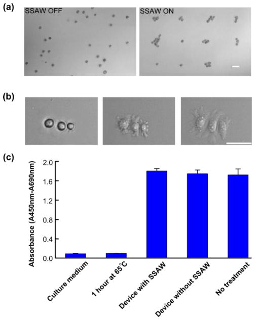
In addition to particle patterning and transportation, we further explored our reusable acoustic tweezers with cell manipulation. We assembled a PDMS-glass microfluidic chip onto a SAW substrate with two orthogonally arranged parallel IDT pairs. A HeLa S3 cell suspension was injected into the PDMS-glass microfluidic chip. Without an acoustic field, all the cells were randomly distributed. Once a two-dimensional acoustic field was applied, the cells were trapped into a dot-like array (Fig. 5a). The patterned cell assemblies were dropped onto the glass substrate (coated with fibronectin) of the PDMS-glass microfluidic chip by removing the acoustic field. Within 20 minutes, all the cells began to attach onto the glass substrate. The PDMS-glass microfluidic chip was removed from the SAW substrate with the cell patterns well preserved. As a result, the cells in the disposable device can be cultured in a normal cell culture incubator. We recorded the images of a target cell assembly every 5 minutes. Fig. 5b shows that the cells were adhered to the glass substrate, and started to undergo a spreading of morphology within a half-hour of incubation.
Fig. 5.
Cell manipulation using of the reusable acoustic tweezers. (a) Images of 2D cell patterning with coupling method (without and with SSAW field). (b) Time-lapsed images of trapped cells (HeLa S3) in a disposable device after being trapped, removed from the LiNbO3 substrate, and cultured in the incubator for a half-hour. (c) Cell viability test using WST-1 assay. HeLa cells were treated through the disposable device with or without coupled SSAWs or incubated at 65°C for 1 hour. Cells without treatment or culture medium were used for a positive or negative control. Scale bar: 50 μm.
To exam the biocompatibility of our method, WST-1 assays were conducted to measure the viability of cells after acoustic treatment. We chose culture medium (first bar) and cells without any treatment (last bar) as a negative and positive control, respectively. Fig. 5c shows that cells treated at 65 °C for 1 hour (second bar) has a similar absorbance value as the culture medium (lower than 0.2); and the cells passed through the disposable device with (third bar) or without (fourth bar) coupled SSAWs have a similar viability as the positive control (between 1.6 and 1.8). The p-values between the groups of the disposable device with or without coupled SSAWs and the positive control were calculated as 0.2150 and 0.7139, respectively. Both p-values are larger than 0.05, which indicates that our method has minimal impact on the cell viability.
Conclusions
We present a reusable acoustic tweezer technology which introduces a SSAW field into a disposable PDMS-glass device. Our platform technology can trap suspended micro-objects for patterning with a tunable geometry or transportation through phase shifts. The successful application of our approach is demonstrated by manipulating and culturing cells in a disposable device with confirmed cell viability. Based on the disposable, contactless, and label-free acoustic tweezers, our approach offers a simple, low-cost, and biocompatible method for manipulating cells and particles which can be integrated into various micro total analytical systems (μTAS), particularly in point-of-care diagnostics.48–50
Acknowledgments
We gratefully acknowledge financial support from National Institutes of Health (1 R01 GM112048-01A1 and 1R33EB019785-01), National Science Foundation (IIP-1534645 and IDBR-1455658), and the Penn State Center for Nanoscale Science (MRSEC) under grant DMR-1420620. Components of this work were conducted at the Penn State node of the NSF-funded National Nanotechnology Infrastructure Network (NNIN).
References
- 1.El-Ali J, Sorger PK, Jensen KF. Nature. 2006;442:403–411. doi: 10.1038/nature05063. [DOI] [PubMed] [Google Scholar]
- 2.Sackmann EK, Fulton AL, Beebe DJ. Nature. 2014;507:181–189. doi: 10.1038/nature13118. [DOI] [PubMed] [Google Scholar]
- 3.Yager P, Edwards T, Fu E, Helton K, Nelson K, Tam MR, Weigl BH. Nature. 2006;442:412–418. doi: 10.1038/nature05064. [DOI] [PubMed] [Google Scholar]
- 4.Wang Z, Zhe J. Lab Chip. 2011;11:1280–1285. doi: 10.1039/c0lc00527d. [DOI] [PubMed] [Google Scholar]
- 5.Gubala V, Harris LF, Ricco AJ, Tan MX, Williams DE. Anal Chem. 2012;84:487–515. doi: 10.1021/ac2030199. [DOI] [PubMed] [Google Scholar]
- 6.Chan CPY, Mak WC, Cheung KY, Sin KK, Yu CM, Rainer TH, Renneberg R. Annu Rev Anal Chem. 2013;6:191–211. doi: 10.1146/annurev-anchem-062012-092641. [DOI] [PubMed] [Google Scholar]
- 7.Yager P, Domingo GJ, Gerdes J. Annu Rev Biomed Eng. 2008;10:107–144. doi: 10.1146/annurev.bioeng.10.061807.160524. [DOI] [PubMed] [Google Scholar]
- 8.Mao X, Huang TJ. Lab Chip. 2012;12:1412–1416. doi: 10.1039/c2lc90022j. [DOI] [PMC free article] [PubMed] [Google Scholar]
- 9.Bruus H, Dual J, Hawkes J, Hill M, Laurell T, Nilsson J, Radel S, Sadhal S, Wiklund M. Lab Chip. 2011;11:3579–3580. doi: 10.1039/c1lc90058g. [DOI] [PubMed] [Google Scholar]
- 10.Friend J, Yeo LY. Rev Mod Phys. 2011;83:647–704. [Google Scholar]
- 11.Ding X, Li P, Lin SCS, Stratton ZS, Nama N, Guo F, Slotcavage D, Mao X, Shi J, Costanzo F, Huang TJ. Lab Chip. 2013;13:3626–3649. doi: 10.1039/c3lc50361e. [DOI] [PMC free article] [PubMed] [Google Scholar]
- 12.Destgeer G, Sung HJ. Lab Chip. 2015;15:2722–2738. doi: 10.1039/c5lc00265f. [DOI] [PubMed] [Google Scholar]
- 13.Barnkob R, Augustsson P, Laurell T, Bruus H. Lab Chip. 2010;10:563–570. doi: 10.1039/b920376a. [DOI] [PubMed] [Google Scholar]
- 14.Muller PB, Rossi M, Marín ÁG, Barnkob R, Augustsson P, Laurell T, Kähler CJ, Bruus H. Phys Rev E. 2013;88:023006. doi: 10.1103/PhysRevE.88.023006. [DOI] [PubMed] [Google Scholar]
- 15.Shi J, Ahmed D, Mao X, Lin SCS, Lawit A, Huang TJ. Lab Chip. 2009;9:2890–2895. doi: 10.1039/b910595f. [DOI] [PubMed] [Google Scholar]
- 16.Li S, Ding X, Mao Z, Chen Y, Nama N, Guo F, Li P, Wang L, Cameron CE, Huang TJ. Lab Chip. 2015;15:331–338. doi: 10.1039/c4lc00903g. [DOI] [PMC free article] [PubMed] [Google Scholar]
- 17.Zeng Q, Li L, Ma HL, Xu J, Fan Y, Wang H. Appl Phys Lett. 2013;102:213106. [Google Scholar]
- 18.Laurell T, Petersson F, Nilsson A. Chem Soc Rev. 2007;36:492–506. doi: 10.1039/b601326k. [DOI] [PubMed] [Google Scholar]
- 19.Franke T, Braunmüller S, Schmid L, Wixforth A, Weitz DA. Lab Chip. 2010;10:789–794. doi: 10.1039/b915522h. [DOI] [PubMed] [Google Scholar]
- 20.Ding X, Lin SCS, Kiraly B, Yue H, Li S, Chiang IK, Shi J, Benkovic SJ, Huang TJ. Proc Natl Acad Sci U S A. 2012;109:11105–11109. doi: 10.1073/pnas.1209288109. [DOI] [PMC free article] [PubMed] [Google Scholar]
- 21.Guo F, Li P, French JB, Mao Z, Zhao H, Li S, Nama N, Fick JR, Benkovic SJ, Huang TJ. Proc Natl Acad Sci U S A. 2015;112:43–48. doi: 10.1073/pnas.1422068112. [DOI] [PMC free article] [PubMed] [Google Scholar]
- 22.Li P, Mao Z, Peng Z, Zhou L, Chen Y, Huang PH, Truica CI, Drabick JJ, El-Deiry WS, Dao M, Suresh S, Huang TJ. Proc Natl Acad Sci U S A. 2015;112:4970–4975. doi: 10.1073/pnas.1504484112. [DOI] [PMC free article] [PubMed] [Google Scholar]
- 23.Guo F, Zhou W, Li P, Mao Z, Yennawar NH, French JB, Huang TJ. Small. 2015;11:2733–2737. doi: 10.1002/smll.201403262. [DOI] [PMC free article] [PubMed] [Google Scholar]
- 24.Chen Y, Ding X, Lin SS, Yang S, Huang P, Nama N, Zhao Y, Nawaz AA, Guo F, Wang W, Gu Y, Mallouk TE, Huang TJ. ACS Nano. 2013;7:3306–3314. doi: 10.1021/nn4000034. [DOI] [PMC free article] [PubMed] [Google Scholar]
- 25.Ai Y, Sanders CK, Marrone BL. Anal Chem. 2013;85:9126–9134. doi: 10.1021/ac4017715. [DOI] [PMC free article] [PubMed] [Google Scholar]
- 26.Destgeer G, Ha BH, Park J, Jung JH, Alazzam A, Sung HJ. Anal Chem. 2015;87:4627–4632. doi: 10.1021/acs.analchem.5b00525. [DOI] [PubMed] [Google Scholar]
- 27.Antfolk M, Muller PB, Augustsson P, Bruus H, Laurell T. Lab Chip. 2014;14:2791–2799. doi: 10.1039/c4lc00202d. [DOI] [PubMed] [Google Scholar]
- 28.Gesellchen F, Bernassau aL, Déjardin T, Cumming DRS, Riehle MO. Lab Chip. 2014;14:2266–75. doi: 10.1039/c4lc00436a. [DOI] [PubMed] [Google Scholar]
- 29.Christakou AE, Ohlin M, Önfelt B, Wiklund M. Lab Chip. 2015;15:3222–3231. doi: 10.1039/c5lc00436e. [DOI] [PubMed] [Google Scholar]
- 30.Shi J, Huang H, Stratton Z, Huang Y, Huang TJ. Lab Chip. 2009;9:3354–3359. doi: 10.1039/b915113c. [DOI] [PubMed] [Google Scholar]
- 31.Shi J, Yazdi S, Lin SCS, Ding X, Chiang IK, Sharp K, Huang TJ. Lab Chip. 2011;11:2319–2324. doi: 10.1039/c1lc20042a. [DOI] [PMC free article] [PubMed] [Google Scholar]
- 32.Ding X, Shi J, Lin SCS, Yazdi S, Kiraly B, Huang TJ. Lab Chip. 2012;12:2491–1497. doi: 10.1039/c2lc21021e. [DOI] [PMC free article] [PubMed] [Google Scholar]
- 33.Li S, Ding X, Guo F, Chen Y, Lapsley MI, Lin SS, Wang L, Mccoy JP, Cameron CE, Huang TJ. Anal Chem. 2013;85:5468–5474. doi: 10.1021/ac400548d. [DOI] [PMC free article] [PubMed] [Google Scholar]
- 34.Ding X, Peng Z, Lin SCS, Geri M, Li S, Li P, Chen Y, Dao M, Suresh S, Huang TJ. Proc Natl Acad Sci U S A. 2014;111:12992–12997. doi: 10.1073/pnas.1413325111. [DOI] [PMC free article] [PubMed] [Google Scholar]
- 35.Ren L, Chen Y, Li P, Mao Z, Huang P, Rufo J, Guo F, Wang L, Mccoy JP, Levine SJ, Huang TJ. Lab Chip. 2015;15:3870–3879. doi: 10.1039/c5lc00706b. [DOI] [PMC free article] [PubMed] [Google Scholar]
- 36.Hodgson RP, Tan M, Yeo L, Friend J. Appl Phys Lett. 2009;94:024102. [Google Scholar]
- 37.Bourquin Y, Wilson R, Zhang Y, Reboud J, Cooper JM. Adv Mater. 2011;23:1458–1462. doi: 10.1002/adma.201004455. [DOI] [PubMed] [Google Scholar]
- 38.Bourquin Y, Reboud J, Wilson R, Cooper JM. Lab Chip. 2010;10:1898–1901. doi: 10.1039/c004506c. [DOI] [PubMed] [Google Scholar]
- 39.Wilson R, Reboud J, Bourquin Y, Neale SL, Zhang Y, Cooper JM. Lab Chip. 2011;11:323–328. doi: 10.1039/c0lc00234h. [DOI] [PubMed] [Google Scholar]
- 40.Reboud J, Bourquin Y, Wilson R, Pall GS, Jiwaji M, Pitt AR, Graham A. Proc Natl Acad Sci U S A. 2012;109:15162–15167. doi: 10.1073/pnas.1206055109. [DOI] [PMC free article] [PubMed] [Google Scholar]
- 41.Schmid L, Wixforth A, Weitz DA, Franke T. Microfluid Nanofluidics. 2011;12:229–235. [Google Scholar]
- 42.Witte C, Reboud J, Wilson R, Cooper JM, Neale SL. Lab Chip. 2014;14:4277–4283. doi: 10.1039/c4lc00749b. [DOI] [PubMed] [Google Scholar]
- 43.Guckenberger DJ, de Groot T, Wan AMD, Beebe D, Young E. Lab Chip. 2015;15:2364–2378. doi: 10.1039/c5lc00234f. [DOI] [PMC free article] [PubMed] [Google Scholar]
- 44.Langelier SM, Yeo LY, Friend J. Lab Chip. 2012;12:2970–2976. doi: 10.1039/c2lc40085e. [DOI] [PubMed] [Google Scholar]
- 45.Jo MC, Guldiken R. Microelectron Eng. 2014;113:98–104. [Google Scholar]
- 46.Hammarström B, Evander M, Barbeau H, Bruzelius M, Larsson J, Laurell T, Nilsson J. Lab Chip. 2010;10:2251–2257. doi: 10.1039/c004504g. [DOI] [PubMed] [Google Scholar]
- 47.Meng L, Cai F, Zhang Z, Niu L, Jin Q, Yan F, Wu J, Wang Z, Zheng H. Biomicrofluidics. 2011;5:44104. doi: 10.1063/1.3652872. [DOI] [PMC free article] [PubMed] [Google Scholar]
- 48.Reyes DR, Iossifidis D, Auroux P, Manz A. Anal Chem. 2002;74:2623–2636. doi: 10.1021/ac0202435. [DOI] [PubMed] [Google Scholar]
- 49.Huang PH, Ren L, Nama N, Li S, Li P, Yao X, Cuento RA, Wei CH, Chen Y, Xie Y, Nawaz AA, Alevy YG, Holtzman MJ, McCoy JP, Levine SJ, Huang TJ. Lab Chip. 2015;15:3125–3131. doi: 10.1039/c5lc00539f. [DOI] [PMC free article] [PubMed] [Google Scholar]
- 50.Zhe J, Jagtiani A, Dutta P, Hu J, Carletta J. J Micromechanics Microengineering. 2007;17:304–313. [Google Scholar]


