Abstract
Frequency modulated Kelvin probe force microscopy (FM-KFM) is the method of choice for high resolution measurements of local surface potentials, yet on coarse topographic structures most researchers revert to amplitude modulated lift-mode techniques for better stability. This approach inevitably translates into lower lateral resolution and pronounced capacitive averaging of the locally measured contact potential difference. Furthermore, local changes in the strength of the electrostatic interaction between tip and surface easily lead to topography crosstalk seen in the surface potential. To take full advantage of the superior resolution of FM-KFM while maintaining robust topography feedback and minimal crosstalk, we introduce a novel FM-KFM controller based on a Kalman filter and direct demodulation of sidebands. We discuss the origin of sidebands in FM-KFM irrespective of the cantilever quality factor and how direct sideband demodulation enables robust amplitude modulated topography feedback. Finally, we demonstrate our single-scan FM-KFM technique on an active nanoelectronic device consisting of a 70 nm diameter InAs nanowire contacted by a pair of 120 nm thick electrodes.
Keywords: capacitive crosstalk, frequency modulation, Kalman filter, Kelvin probe force microscopy, sidebands
Introduction
Device performance of current nanoelectronic devices, and even more so of potential future generations including nanowires or molecular junctions, critically depends on transport properties varying on a length scale of a few nanometres only in the active channel or at electrode interfaces. Methods for local electronic characterisation, providing accurate measurements with nanometre spatial resolution, are in very high demand, but have been lagging behind the technological requirements.
Kelvin probe force microscopy (KFM) is an established technique that allows for the mapping of local electrostatic potentials with an atomic force microscope (AFM) [1–3]. In contrast to electrostatic force microscopy (EFM), which measures merely the effect of electrostatic forces on the oscillation of the tip, a feedback loop nullifies the electric field by adjusting a bias voltage between tip and sample. Hence, Kelvin probe force microscopy is able to quantify the local contact potential difference (CPD), Ulcpd, which contains contributions, e.g., from the difference in work function between the AFM tip and structures on the sample, dopants and trapped charges in the device, or voltages applied to electrodes.
For electronic devices on the nanoscale, KFM measurements provide a unique tool to shed light upon a variety of otherwise inaccessible properties. For example, with a constant current passing through a two-terminal device, the potential drop at the contacts directly relates to the contact resistance. To extract contact resistance through traditional four-point measurements becomes increasingly difficult for scaled devices, in which the contact length is comparable to the device length. Recently, KFM has been used to extract the surface state density and Schottky depletion region in semiconductor nanowires [4–5] or to determine the mean free path in carbon nanotubes [6]. KFM also allows one to determine intrinsic doping of two-dimensional crystals such as graphene [7–8], where surface potential and electronic properties depend on the number of layers.
KFM has found widespread use in both vacuum and ambient environments. Most commercial instruments for operation in air include a scan mode based on amplitude modulation KFM (AM-KFM). In this mode, the feedback loop nullifies the cantilever oscillation that is excited by a modulated electrostatic force. Hence, the KFM image is a map of voltages required to compensate the electrostatic force at every point of the scanned field. However, since cantilever and AFM tip are extended objects, this voltage does not necessarily correspond to the local contact potential difference, Ulcpd, but represents a weighted average over the potentials present on the entire sample surface [9]. For AM-KFM, the weights are determined by the capacitance gradient, C', between the probe and the sample. Due to the long range electrostatic force, even parts far from the surface, such as the cantilever beam, can account for a significant fraction of the signal, limiting the spatial resolution and accuracy of the measurement. Within nanoscale devices, for example, electrode potentials may completely overshadow the channel [10].
Known approaches to increase spatial resolution and accuracy of surface potential measurements include deconvolution techniques [11–12] or the use of slightly blunt tips supported by a cantilever of minimal surface area [9]. However, deconvolution techniques require a detailed model of the AFM tip to be accurate and usually neglect the sample topography [12], whereas blunt tips inevitably reduce topography resolution on three-dimensional structures.
KFM measurements are further complicated by a strong dependence of the detected signal on the tip–sample distance. In the often employed lift-mode schemes, each line is scanned twice: first to acquire topography, and subsequently to retrace the scanned line at a small distance, Δz, above the surface to perform KFM measurements. This enables tuning the ac modulation frequency for KFM to resonance to enhance the signal, and, at the same time, to reduce the contribution of van der Waals forces to the total force measured and compensated. The scan at elevated height, however, reduces lateral resolution and accuracy of the KFM data as we will detail below. To minimise such lateral averaging, single-scan methods are preferred, performing topography and KFM measurements simultaneously. An additional benefit of single-scan AFM and KFM is the inherent suppression of electrostatically induced topography artefacts present in non-compensated topography scans [13–14]. In AM-KFM, single-scan methods can be implemented taking advantage of multiple eigenmodes of the cantilever, using one mode for topography and another for KFM. Nevertheless, the averaging effect of the cantilever beam remains (see below in Figure 1).
Figure 1.
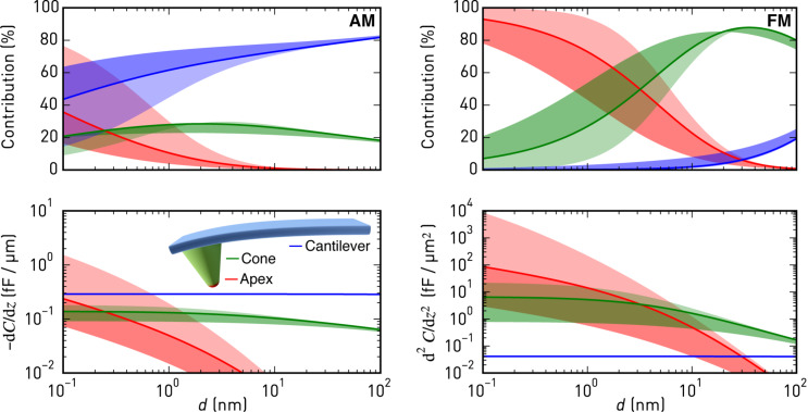
Contributions of apex, cone, and cantilever to the first (AM, left) and second (FM, right) order capacitance gradient as a function of distance for a mechanical oscillation amplitude of 5 nm (solid line) and an Olympus AC160 cantilever (rtip = 5 nm, Htip = 14 μm, θ = 17.5°, and Alever = 160 μm × 40 μm). The light (dark) shaded regions indicate the range up to A = 0.1 nm (50 nm).
An alternative approach typically applied in vacuum is based on frequency modulation [15]. To this end, the frequency of the cantilever is usually tracked by a phase-locked loop (PLL). Its output signal, the frequency shift Δf, exhibits a frequency component at the electrostatic modulation frequency, which is nullified by the Kelvin feedback loop. Frequency modulated KFM (FM-KFM) [16–17] thus provides a map of potentials required to minimise the electrostatic force gradient, proportional to Δf for small mechanical amplitudes, at every point during the scan. As a consequence, the contributions from different parts of the sample and the probe to the measured signal are weighted by the second-order capacitance gradient, C'', which effectively eliminates the averaging contribution of the cantilever beam as we explain in the following.
Figure 1 shows a model calculation using typical cantilever and interaction parameters, summarising how much tip apex, cone, and beam of an AFM cantilever probe contribute to the measured KFM signal in AM and FM operation. Shown are the percentages of the contributions and corresponding weighting factors C' and C'' for AM and FM, respectively. To this end, we applied an analytic model of the electrostatic tip–sample interaction force [18] to the approximate geometry of a typically used cantilever (Olympus AC160), and we calculated C' and C'' as a function of tip–sample separation for different oscillation amplitudes (see Supporting Information File 1 for details). While tip apex and cone clearly dominate the FM-KFM signal, opening the avenue to high resolution quantitative imaging, the cantilever beam at a distance of 14 μm dominates the AM-KFM signal even close to the sample, which is the main reason for the notoriously low lateral resolution and poor potential accuracy in this mode. When comparing AM and FM modes, one should note that in lift-mode AM-KFM the cantilever is not oscillating anymore when the electrostatic forces are nullified, whereas the mechanical oscillation remains in multifrequency AM-KFM and FM-KFM. Hence, for lift-mode the case A → 0 should be considered, whereas in single-scan modes the oscillation applied for tracking topography remains. For best sensitivity and minimal spatial averaging, AM and FM modes need to be operated very close to the surface.
While the FM-KFM approach is clearly superior in terms of signal composition, several issues complicate its use in practice. First, it is often performed together with frequency modulated topography feedback that employs a PLL to determine Δf. The non-monotonous tip–sample interaction, by which Δf can change its slope between net-attractive and net-repulsive forces, can complicate stable operation of the topography feedback and may ultimately render PLL and amplitude controller unstable. On samples with coarse topography and steep features, maintaining stable FM topography feedback demands careful selection of operating parameters and slow scanning speeds. Furthermore, the choice of suitable bandwidths for topography and KFM feedback is more involved in traditional FM-AFM/FM-KFM implementations. For example, when Δf is used as an input to the lock-in amplifier detecting the electrostatic modulation, the PLL bandwidth must be wide enough to include the modulation frequency. Yet, it should be kept as small as possible for stable PLL operation and maximum noise rejection [19]. Finally, the pronounced distance dependence of C'' for apex and cone, as depicted in Figure 1, makes operation close to the surface more challenging, since small errors of the topography feedback produce marked changes of the effective Kelvin feedback gain. Similarly, when the tip encounters steep edges in topography, C'' may increase due to a larger effective tip–sample capacitor area, further complicating stable feedback operation. The distance dependence is less pronounced at larger distances employed in lift-mode FM-KFM [10], but in addition to reduced lateral resolution, large modulation voltages are required due to weaker signals [20], which may induce band bending. Furthermore, when scanning across insulating parts of devices, such as gate oxides, not only the local dielectric constant changes, but because of their thickness also a limit is put on the minimum approachable distance in Figure 1. As a result, deliberately slow feedback settings to ensure stable operation are common practice.
In this paper, we describe a practical approach to FM-KFM providing solutions to these issues. We remove the interdependence of topography and KFM feedbacks by focusing on the information contained in the sidebands produced by the electrostatic modulation [20]. Employing a commercially available lock-in amplifier, we detect these sidebands directly. Thus, with frequency modulated distance feedback, the PLL bandwidth can be restricted to the topography only. We further demonstrate the advantage of combining FM-KFM with amplitude modulated AFM (AM-AFM) for tracking topography of highly structured surfaces with small amplitudes and net-attractive interaction in air. Since the oscillation amplitude decreases monotonically with distance, no special precautions are required to ensure feedback stability. Finally, we introduce an improved Kelvin feedback loop based on stochastic optimal control that continuously adjusts its sensitivity to local changes in C'', thereby reducing the risk of feedback instabilities and topography crosstalk on difficult heterogeneous samples.
Theory
The origin of sidebands
The cantilever motion and the origin of sidebands are understood from a damped harmonic oscillator driven by an external drive, a(t), and perturbed by the tip–sample interaction force  ,
,
 |
[1] |
where z(t) is the cantilever deflection, ω0 the eigenfrequency, k the spring constant, and Q the quality factor of the cantilever. For an oscillation with amplitude A and drive frequency ωd ≈ ω0, the interaction force can be approximated to

where z0 is the mean tip position, and  and
and  are the effective force and force gradient, respectively. Explicit expressions for the effective force and force gradient, averaged over the oscillation period, T ≈ 2π/ωd, are [21]
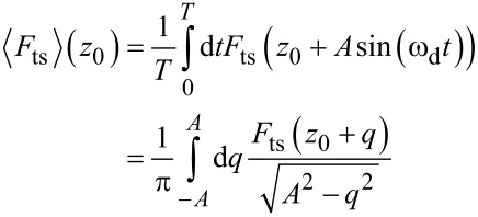 |
[2] |
and
 |
[3] |
The effective force and force gradient, as introduced here, allow one to describe the motion of the tip in the non-linear force field close to the sample with the model of a perturbed harmonic oscillator, provided the oscillation remains approximately harmonic with constant amplitude [22].
With a small perturbation, kts << k, the resonant frequency of the cantilever changes from ω0 to ω0 + Δω with Δω/ω0 = −kts/2k [15]. Accordingly, a modulation of the force gradient, e.g., by an oscillating electric field, will cause a frequency modulation of the resonance. A modulation at a single frequency ωm will produce sidebands at integer multiples of the modulation frequency, that is, cantilever oscillations at ω0 ± ωm, ω0 ± 2ωm and so on.
For the derivation of the sideband signals and their respective amplitudes, we assume a modulation of the force gradient at the frequency ωm:  . Note that the effective force gradient as calculated above, Equation 3, is valid for ωm
<< ωd.
Then, by Fourier transformation of the equation of motion, Equation 1, we arrive at
 |
[4] |
with
 |
[5] |
where  and
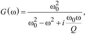
and  are the Fourier transformed deflection and drive, respectively, and G(ω) is the complex transfer function of the damped harmonic oscillator.
Equation 4 and Equation 5 present an iterative scheme to determine the spectral components of the cantilever oscillation, where in each step  on the left hand side of Equation 4 is refined by the expressions on the right hand side. Starting from an oscillator at rest,
  is the carrier oscillation due to the external drive, as in the unperturbed system. Spectral components at ω ± ωm emerge in the next iteration step,
 |
[6] |
This is the fundamental pair of sidebands of the force modulated damped harmonic oscillator. With  << k, the higher order sidebands arising in the subsequent iterations are usually negligible.
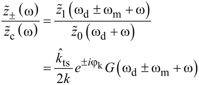
Equation 6 also describes the sideband amplitude transfer function when the expression is evaluated close to the sideband frequencies. With the substitution ω − ωd → ω, we find
 |
[7] |
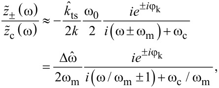
with the approximation
 |
[8] |
where, in the latter approximation, we consider only the dominant term for a drive close to the eigenfrequency, i.e., ωd ≈ ω0 and ω << ω0, and ωc = ω0/2Q is the cantilever bandwidth.
For modulation frequencies well beyond the cantilever bandwidth, G(ω0 ± ωm) ≈ −iω0/2ωm, and the amplitude of each sideband is  , where A is the carrier amplitude. The latter expression also follows immediately from a narrow-band frequency modulation of a carrier oscillation at ωd. With a carrier amplitude A and the peak frequency deviation
  , a frequency modulation at ωm produces two sidebands with amplitudes βA/2, where
  is the modulation index [23]. Under ultra-high vacuum conditions, large Q factors typically cause negligible cantilever bandwidths, making this approximation valid, e.g., for finding the noise power spectral density of the frequency shift signal in FM-AFM [24]. When the narrow-band conditions are not met (β >> 1), the iterative scheme for the sideband amplitudes in Equation 4 and Equation 5 still approaches the Bessel functions describing the sideband amplitudes in a general frequency modulation for ωm
>> ωc (see Supporting Information File 1).
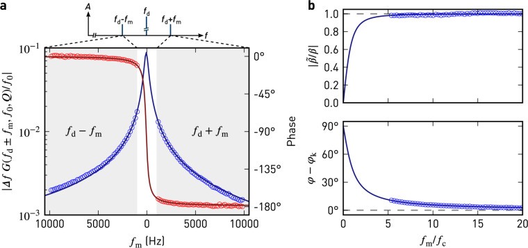
The Fourier approach presented above also accurately models the behaviour of the sideband amplitude and phase for modulation frequencies approaching the cantilever bandwidth ωc. In Figure 2a, we show the expected and experimentally measured sideband amplitudes and phases. The excellent agreement with the above model proves the validity of our derivation. Each sideband is phase-shifted by ±φk + argG(ωd ± ωm).
Figure 2.
a) Sideband amplitude (blue) and phase (red) relative to the carrier oscillation measured during a sweep of the modulation frequency (markers), and a fit of the harmonic oscillator (solid lines). At a constant height of approx. 25 nm above the sample, the tip was driven mechanically at fd = ωd/2π = 70657 Hz and electrically at fm. Parameters to the least-squares fit are  = 33 Hz, f0 = 70586 Hz, and Q = 190. b) Amplitude and phase of the complex modulation index for a narrow-band frequency modulation,
  . The solid lines are a plot of the approximation in Equation 9. The dashed lines indicate the expected behaviour for fm>> fc, neglecting the influence of the damped harmonic oscillator.
For narrow-band frequency modulation, we can define a complex modulation index  by the sideband and carrier amplitudes as
  . With Equation 8, the dc response (ω → 0) of
  thus is
 |
[9] |
Figure 2b shows the amplitude and phase of  for pure narrow-band FM and the harmonic oscillator as a function of ωm/ωc. The amplitude and phase only agree with the result for pure narrow-band frequency modulation when the cantilever bandwidth is negligible compared to the modulation frequency. For low modulation frequencies
  approaches
  instead (Equation 9).
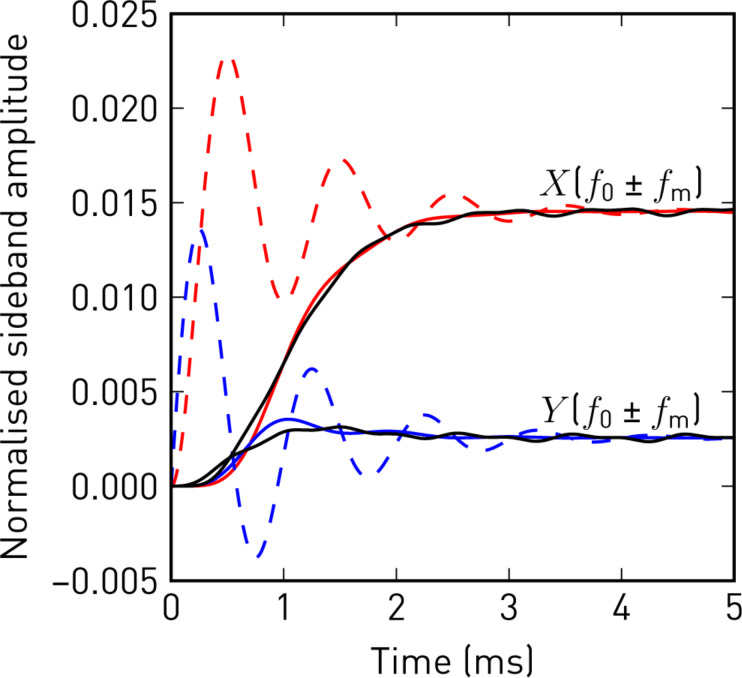
To further demonstrate the validity of the sideband transfer function, we show in Figure 3 the response to a step in  from both the approximation in Equation 8 and from a numerical simulation of the perturbed harmonic oscillator, Equation 1, including lock-in amplifiers at ωd ± ωm. Each change in the force gradient modulation also excites a transient oscillation at the resonant frequency of the cantilever, which appears in the sideband signal and decays exponentially with 1/ωc. Therefore, the filter settings of the lock-in amplifier should be set accordingly to provide sufficient rejection near ωm.
Figure 3.
In-phase (red) and quadrature (blue) sideband amplitudes, normalised to the carrier oscillation amplitude A, in response to a step in the force gradient modulation amplitude. The step responses following from Equation 8 (dashed), show oscillations at fm, exponentially decaying with 1/ωc, which are removed by the low-pass filter of the lock-in amplifier (solid, fcut = 250 Hz, 24 dB/oct). The solid black lines show the demodulated sideband amplitudes from a direct numerical simulation of the perturbed harmonic oscillator. (Numerical parameters: f0 = 70500 Hz, Q = 200, A = 10 nm, fm = 1000 Hz, φk = 0,  = 30 Hz).
We conclude that sidebands evolve as soon as kts gets modulated and it is not important whether the resonant frequency is actually tracked or not. The main benefit of tracking the resonant frequency (e.g., with a phase-locked loop) is merely to keep the carrier phase constant, which would otherwise affect the sideband phases.
Electrostatic force and force gradient
The electrostatic force between the AFM tip and sample is

where  is the effective capacitance gradient, Uts is the tip–sample voltage, and Ulcpd is the local contact potential difference.
For Kelvin probe force microscopy, Uts is modulated around a dc voltage: Uts = Udc + Uac cos(ωmt). Therefore, the electrostatic force and likewise its gradient,  , are modulated at ωm and 2ωm,

where
 |
[10] |
 |
[11] |
and
 |
[12] |
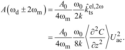
These modulations of the force gradient cause sidebands of the cantilever deflection at ωd ± ωm and ωd ± 2ωm, which can be detected directly with lock-in amplifiers at the respective frequencies. The lock-in amplifiers return, relative to the reference oscillator, amplitude and phase of each sideband as well as their cartesian projection: the in-phase component X and the quadrature component Y. In the narrow-band approximation for ωm >> ωc, the in-phase components of the modulation at ωm and the amplitudes at 2ωm are
 |
[13] |
and
 |
[14] |
The reference phase offsets of the lock-in amplifier for the first set of sidebands at ±ωm are chosen to maximise their respective in-phase components, taking into account the 180° phase shift of the lower sideband. Then, Xω = X(ωd + ωm) − X(ωd − ωm) =  is the total in-phase component, which depends linearly on the applied dc bias. Furthermore, when Udc matches Ulcpd, Xω is nullified and the ±ωm sidebands disappear.
The total amplitude of the second set of sidebands, A2ω = A(ωd + 2ωm) + A(ωd − 2ωm) =  , only depends on the ac modulation amplitude and the second order capacitance gradient,
  . This signal thus provides a handle for imaging variations in the tip–surface capacitance, surface dielectric properties [25], or lateral dopant profiling [26].
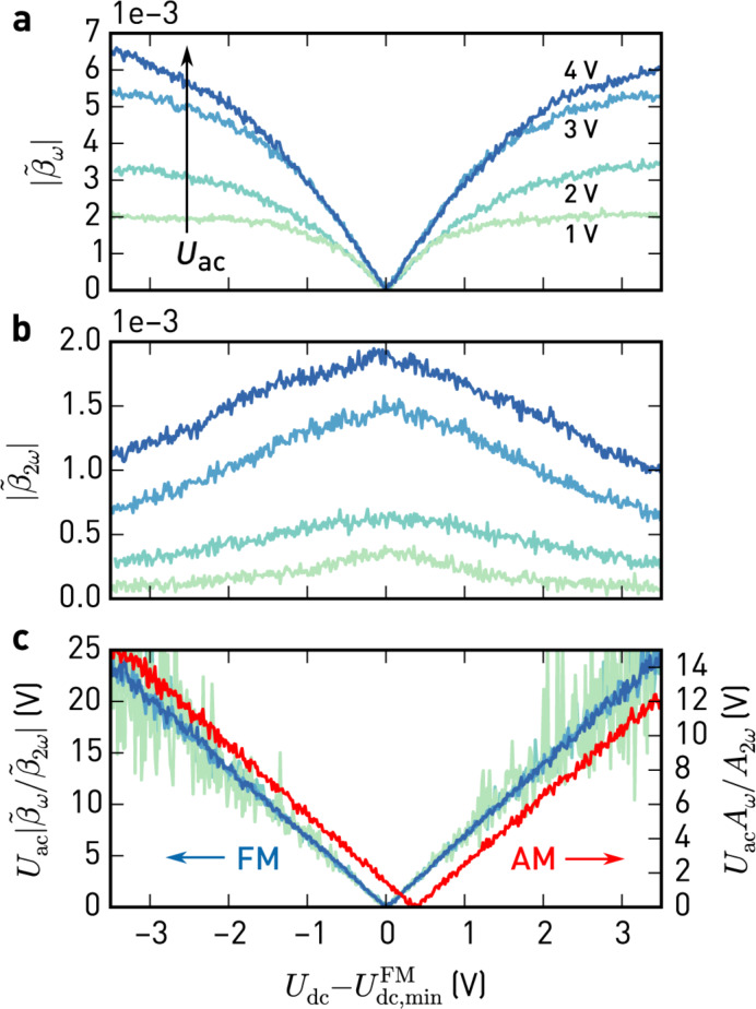
In Figure 4, we show experimental data of modulation indices  and
and  , calculated from the ωm and 2ωm sidebands, respectively, as a function of Udc for different electrostatic modulation amplitudes, Uac. During this experiment, the tip was positioned above a nickel electrode with amplitude modulated topography feedback enabled in net-attractive mode.
Figure 4.
Modulation indices of the sidebands at ωm (a) and 2ωm (b) against  for different modulation amplitudes Uac. Topography feedback in amplitude modulation (net-attractive interaction) was enabled during these measurements.
  , given by the minimum of
  , is the contact potential difference found by FM detection. c) Signals in (a) normalised using Uac and
  (light green to blue, FM). Normalised electrostatic force (red, AM), simultaneously detected with lock-in amplifiers at ωm and 2ωm. (Scan parameters: Afree = 11.2 nm, Aset = 10.4 nm, Q = 500, k = 35 N/m, f0 = 302.5 kHz, fm = 4 kHz).
As expected from Equation 13, the ωm sideband amplitudes (Figure 4a) vanish when Udc = Ulcpd. While they change linearly with Udc close to this point, there are non-linear deviations at larger voltage offsets, which are caused by changes in C''. This is also evident from the 2ωm sideband amplitudes (Figure 4b), showing the decrease of C'' with increasing voltage offsets. Since these sweeps are acquired with topography feedback enabled, the observed variations in C'' are most likely due to changes in the tip–surface separation: The AM topography feedback is sensitive to the static force gradient, which contains electrostatic interactions, Equation 10, that increase as the dc bias does not match the surface potential; consequently, the topography feedback retracts the tip, reducing C''.
In Figure 4c, we plot the ratio of the ωm and 2ωm sideband amplitudes, normalised to Uac. As apparent from Equation 13 and Equation 14, this process cancels out the non-linearities and collapses the sweeps at different Uac to a single curve.
Additionally, we show the similarly normalised amplitudes due to the electrostatic force at ωm and 2ωm in the deflection signal, which we acquired simultaneously with the sidebands at ωd ± ωm. They show the same v-shaped relationship, with their minimum being slightly shifted with respect to the FM case. This shift is due to the different weights of contributions in the AM signal (cf. Figure 1). Setting the dc bias to the minimum obtained by AM-KFM does not guarantee to compensate the electrostatic force gradient and can cause height errors in topography. At the minimum determined from the sidebands,  in Figure 4b reaches its maximum value, corresponding to the closest approach.
There are two major methods to find the local contact potential difference at every point during the scan. Open-loop KFM exploits the fact that the 2ωm amplitudes do depend on C'' but not on Udc − Ulcpd. As demonstrated in Figure 4, the ratio of the ωm and 2ωm sidebands is independent of changes in C'' and only depends on the chosen modulation amplitude and dc bias,
 |
[15] |
hence Ulcpd can easily be determined. Note, however, that the above definition of the prefactor K′ is only valid for modulation frequencies well beyond the cantilever bandwidth. In the general case, K′ = (4/Uac) G(ωd ± ωm)/G(ωd ± 2ωm), that is, it also depends on the resonant frequency and the quality factor, which may change while scanning. Furthermore, there may be differences in the sideband phase shift when Q or ω0 are not constant (cf. Figure 2). Together, such inaccuracies in the model easily translate into uncertainties of Ulcpd in an open-loop method. A PLL can reduce these effects, but then its transfer function needs to be considered as well [27], and the bandwidth must be larger than 2ωm.
In closed-loop KFM, the local contact potential difference is found by nullifying the in-phase components of the ωm sidebands (Equation 13) with a feedback loop adjusting the applied dc voltage [1–3,16]. Thus, the 2ωm sidebands are not necessary to determine the CPD, and the effect of model deviations and non-linearities is cancelled by the feedback. Furthermore, the nulling process also minimises the dc electrostatic force and force gradient (Equation 10), reducing electrostatically induced height errors [14,28–29].
However, a few critical issues remain with simple Kelvin feedback loops. For example, when the sidebands are not completely nullified by the feedback, leaving a small error δ, it follows from Equation 13 that  [30]. C'' depends strongly on the electrostatic interactions between tip and surface and may change significantly on structured surfaces even for a well-tuned topography controller. During a scan, imperfect Kelvin feedback therefore leads to errors in the measured CPD, constituting a source of topography-induced crosstalk.
If additional apparent forces (or force gradients) are detected at the frequencies used for KFM, the Kelvin feedback does not compensate the CPD, but rather nullifies the in-phase component affected by offsets [31]. Such crosstalk is due to parasitic capacitive coupling and observed mainly in AM-KFM, where the electrostatic modulation is at high frequencies [32]. When coupling to the shaker piezo [33], cantilever resonances can amplify this effect.
Another source of crosstalk can appear when ωm is set too low and the Kelvin lock-ins capture the modulation of kts induced by topography. This can happen on highly structured surfaces when the bandwidth of the topography feedback is insufficient for the scan speed. By monitoring the deflection power spectral density near the driving frequency, an upper frequency bound of the remaining kts modulations can be determined. In order to avoid crosstalk, ωm should be chosen above this bound, considering both the bandwidth and filter steepness of the Kelvin lock-ins.
As already mentioned above, the tuning of the Kelvin feedback loop itself can be a challenge because its sensitivity depends on C''. This becomes even more acute for small tip–sample distances and single-scan techniques on structured surfaces, where the tip–surface interaction is not limited to the apex.
In order to address the topography crosstalk due to C'', Lee et al. [34] suggested to use a feedback signal normalised to the 2ωm sideband, thus rendering the CPD tracking error independent of C'' (cf. Equation 15). However, as shown in Figure 4c, the normalisation procedure may introduce additional noise when dividing by small signals, e.g., for low Uac.
In the following section we introduce a novel Kelvin feedback scheme that resolves these subtleties.
Results and Discussion
Optimal CPD estimation and Kelvin control
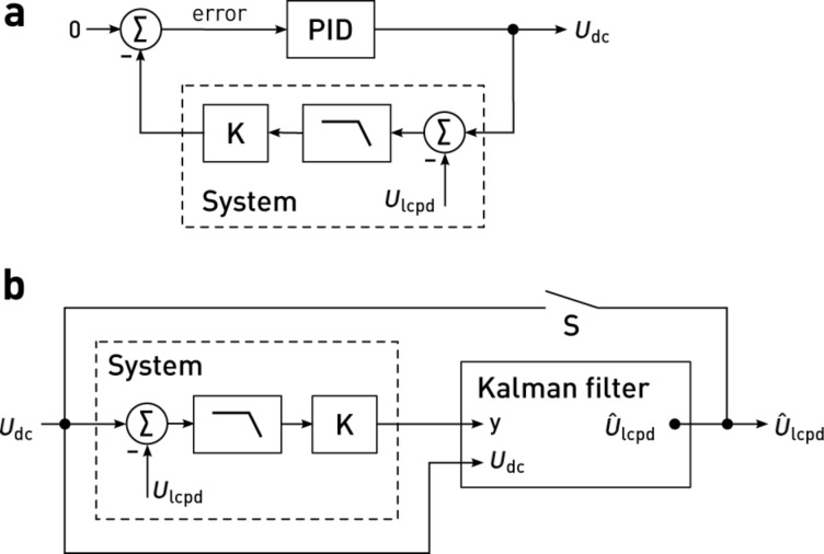
Most instruments provide a generic PID controller for Kelvin control, which compares the signal (Xω) to a setpoint (0), yielding the error signal e. The sum of e, ∫dte, and de/dt, scaled by respective proportional (P), integral (I), and derivative (D) gains, is fed back into the system. In case of KFM, the resulting dc voltage compensates the electrostatic interactions. This standard PID feedback loop is illustrated in Figure 5a. Knowing the system dynamics, a multitude of tuning rules can be applied [35]. In practice, however, the feedback gains are often tuned by trial and error, and the derivative part is omitted altogether [36]. In many cases, only the integral part is necessary for good tracking and to eliminate steady-state errors. Integral-only controllers are therefore prevalent for topography or Kelvin feedback.
Figure 5.
Block diagram of a Kelvin controller based on a) a proportional–integral–differential (PID) controller, and b) the Kalman filter. In the PID controller, the system output is compared to a setpoint to yield the error signal. The output signal, i.e., the sum of amplified errors and their respective integral or derivative, is fed back into the system. When the system output is nullified (setpoint 0), the controller output Udc equals the surface potential Ulcpd. In contrast, knowing an approximate model of the system, the Kalman filter estimates  solely based on the system output and the applied dc bias, Udc. With the switch S closed, the estimated surface potential
  is applied as the dc bias, corresponding to a feedback configuration.
Controllers basing their actions on an error signal only are unaware of the systems they control. Thus, they need to be retuned as soon as the system bandwidths or gains change considerably, either due to different operator settings or, more importantly during KFM scans, due to local variations of electronic properties and topography of the sample. To maintain best feedback settings at every location during a scan, we introduce a novel controller for FM-KFM based on stochastic optimal control [37]. Optimal control and model-based controllers have been successfully used before in AFM, e.g., for active damping of cantilevers [38] or fast scanning [39]. According to the separation principle [37], the optimal controller that minimises the expected error can be constructed by finding an optimal ‘observer’ and an optimal ‘regulator’. As an observer, we use a Kalman filter [40], which continuously blends the sideband measurements at ±ωm into an estimate of the contact potential difference,  , based on a simplified model of the FM-KFM detection system. The Kalman filter is the stochastically optimal observer that minimises the state error covariance [37], taking into account both measurement noise and the uncertainties in the knowledge of its state. Adapted for KFM control, the Kalman filter minimises the estimation error variance of the surface potential,
  . Since the aim of the regulator in KFM is to minimise electrostatic interactions, the optimal regulator is found by matching the dc bias to
  , thereby closing the feedback loop (Figure 5b).
Our Kalman filter design based on a model of the KFM detection system includes the sideband dynamics, Equation 8, the electrostatic force gradients acting on the cantilever, Equation 11 and Equation 12, and the transfer function of the demodulating lock-in amplifier. Since the lock-in bandwidths must be kept well below ωm to avoid carrier and topography crosstalk, the sideband transfer functions reduce to an effective gain and phase, Equation 9. The lock-in transfer function can either be measured or is known from its filter properties. We focus on a particularly simple case, the n-th order critically damped lowpass filter, which is formed by n consecutive first order stages with a time constant τ. With these considerations, the transfer function for the in-phase lock-in components is G(s = iω) = K(1 + τ s)−n, where, following Equation 13, we find the static gain  and the system output G(s)(Udc − Ulcpd).
Based on the transfer function, we find a state-space model of the system, in which we incorporate Ulcpd as a hidden state, and Udc is the control signal. We further model the uncertainties of state transitions ( ) and our measurements as uncorrelated, zero-mean white noise with power spectral densities V and W, respectively. Hence, Ulcpd follows a Wiener process or Brownian motion [37]. For a derivation of the continuous-time Kalman(-Bucy) filter [41], see Supporting Information File 1. In discrete time, the Kalman filter is similarly found from a discrete-time state-space model [40]. In this formulation the state estimate and covariances are refined recursively as new measurements are incorporated:
At the time t, an a priori state and covariance estimate is found using the state and covariances at the time t − Δt, based on the system model. Then, the Kalman gain L is computed from the covariance matrices of the a priori estimated state and the system model. L controls the innovations process, in which the measurements at the time t are incorporated to the a posteriori estimate of state and covariances [42].
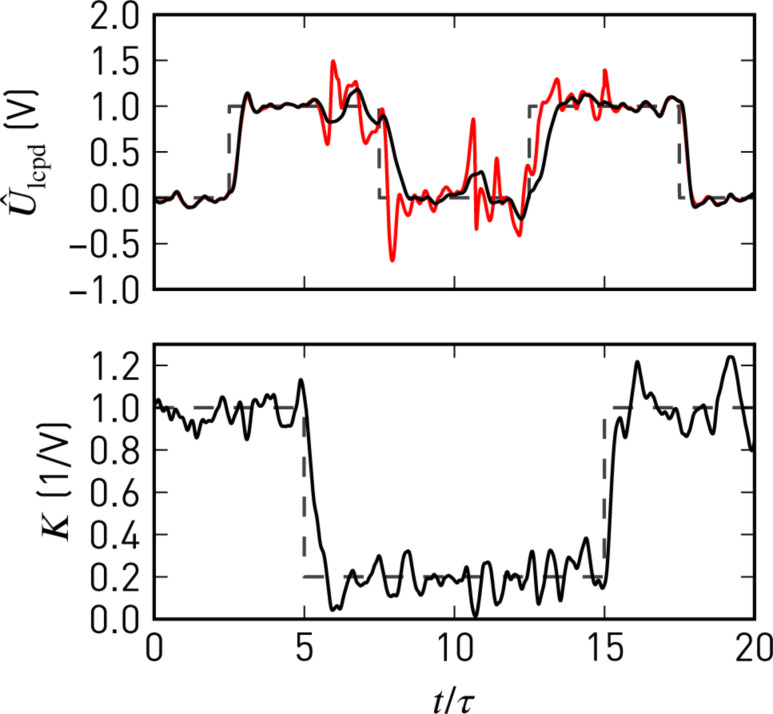
This recursive predictor–corrector structure allows for updates of the system parameters, such as the static gain K, at each instant of the state update. With Equation 15, the 2ω sideband amplitudes can thus be exploited to continuously update K = K'A2ω. Consequently, the observer model will follow changes in the Kelvin signal strength due to variations of C''. This strategy avoids normalisation by potentially noisy C'' signals [34], yet changes in C'' do not affect closed-loop performance. We demonstrate this in Figure 6, where we compare step responses of the closed-loop Kalman observer and PI controller. As soon as the gain K drops, the noise level increases with a PI controller, whereas the Kalman estimate remains clean.
Figure 6.
Closed-loop response of the Kelvin observer (black) and a proportional-integral controller (red) to steps in Ulcpd and K. Both controllers incorporate the separately measured static gain, K, and are tuned for similar step responses at high K. Noise in K and at the inputs is artificial white noise lowpass-filtered with τfcut = 1 and the filter order n = 4, corresponding to the simulated system.
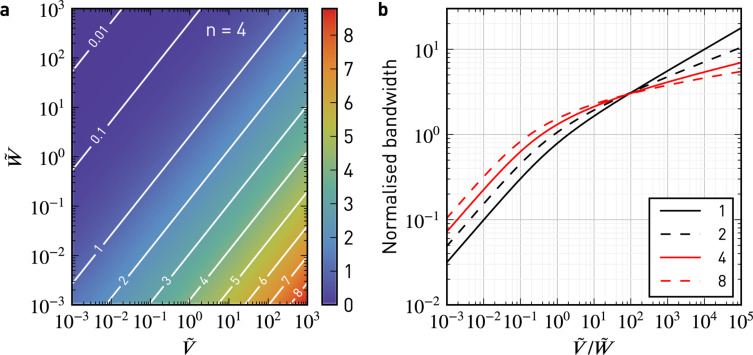
To further elucidate the performance of the controller, we plot in Figure 7 its −3 dB closed-loop bandwidth, normalised to the −3 dB filter bandwidth, as a function of the normalised noise power spectral densities  and
and  of state transitions and observations, respectively. As the noise at the output,
  , increases for a fixed
  , the bandwidth is reduced (Figure 7a). The ratio
  resembles a signal-to-noise ratio (SNR), which increases for large K and small filter bandwidths BW. The closed-loop bandwidth is a function of this SNR. Therefore, in addition to avoiding divisions by small signals, the Kalman filter improves noise performance by bandwidth adjustments. For normalised closed-loop bandwidths ≤ 1, the bandwidth is adjusted following
  (Figure 7b). Larger bandwidths are not desired, since they would counteract the lock-in lowpass action.
Figure 7.
Normalised closed-loop bandwidth (−3 dB) of the steady-state Kelvin observer as a function of the normalised power spectral densities  and
and  for different orders of the low-pass filter, n. a) Two-dimensional map for n = 4. As the observation noise density,
  , increases for a fixed transition noise density,
  , the closed-loop bandwidth is reduced. b) Closed-loop bandwidth normalised to the bandwidth of the corresponding n-th order low-pass filter.
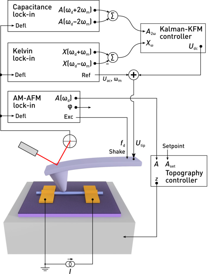
Our setup is shown in Figure 8. We implemented the Kalman-filtering Kelvin controller as a real-time program on the digital signal processor (DSP) of a digital lock-in amplifier and PLL (HF2, Zurich Instruments), which demodulates the sidebands at ωd ± ωm and ωd ± 2ωm as well as the carrier signal at ωd. Since our implementation of the Kalman filter is integrated into the lock-in, all signals are available without additional digital/analog/digital conversions. Additional offsets that might affect the feedback accuracy are avoided. We have implemented the Kalman filter as a reusable component in C++ using the Eigen template library for linear algebra [43], allowing us to perform offline tests with the same code that is compiled for the DSP. In its current state, our custom FM-KFM controller can work at sampling rates of up to 7200 Sa/s.
Figure 8.
Schematic of the modified KFM setup. For topography feedback, the cantilever is excited at a constant frequency ωd close to resonance. Lock-in amplifiers at ωd ± ωm and ωd ± 2ωm detect sidebands of the cantilever oscillation which contain information about the surface potential and tip–sample capacitance. Both contributions are used by the Kalman-KFM controller for the CPD estimate.
Since the sideband signals are detected individually, we do not depend on the Δf signal as in a typical FM-KFM setup. Therefore, the Kelvin feedback remains the same for AM and FM topography feedback schemes. For example, on samples with coarse topography one may use AM topography feedback to avoid instabilities typically experienced with FM operation. In vacuum, this may require additional application of active Q control [44–45] to lower the Q-factor of the cantilever.
Performance on a nanowire device
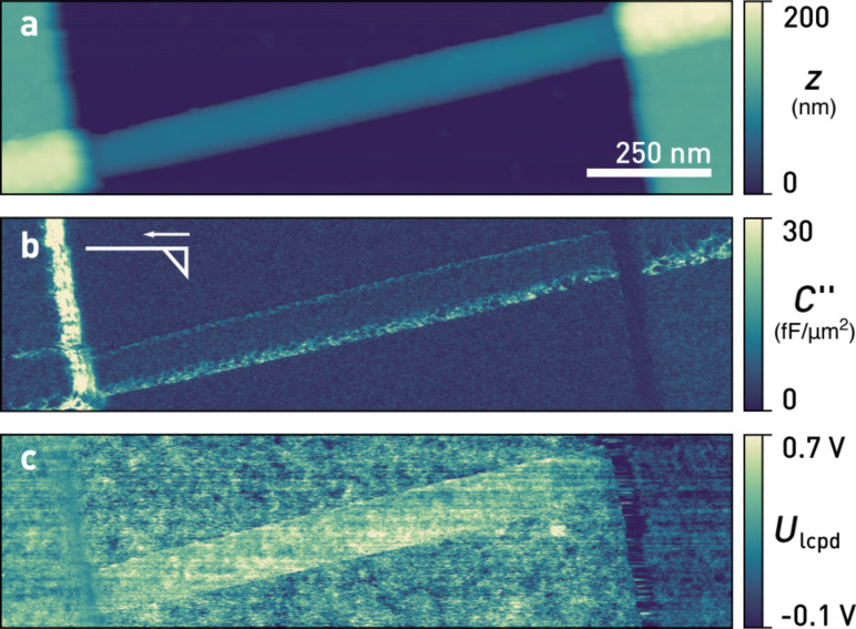
To demonstrate the performance of our Kalman-KFM controller, we examine an active nanowire device as depicted in Figure 8 and Figure 9. Such devices exhibit some of the most typical and relevant issues hindering reliable KFM measurements in the past: a combination of large topography with a multitude of different materials including oxides prone to charging. In Figure 9, we show a scan of a 70 nm diameter indium arsenide (InAs) nanowire with nickel (Ni) contacts (height ≈ 120 nm), obtained at a bias current of 1.4 μA under ambient conditions using a commercial AFM (Cypher, Asylum Research). The steep edges at the electrodes necessitated AM topography feedback. Oftentimes the contact resistances between nanowire and metal contacts are uneven and large, obscuring the electrostatics of devices. Traditional four-point measurements are limited at sub-micron length scales because the contact length can become comparable to the channel dimensions. For such samples, KFM appears to be an ideal tool to characterise the electrostatics in order to optimise device performance, for example as field effect transistors.
Figure 9.
a) Topography, b) tip–sample capacitance gradient, C'', and c) local contact potential difference, Ulcpd, of an InAs nanowire at a bias current of 1.4 μA. Ulcpd, determined by the Kelvin observer, exhibits no crosstalk. The inset in b) indicates the tip shape and fast scan direction. (Scan parameters: Afree = 8.6 nm, Aset = 7.2 nm, Q = 390, k = 26 N/m, f0 = 304.2 kHz, fm = 4 kHz, Uac = 1 V, fcut = 100 Hz, n = 4, vtip = 800 nm/s).
Figure 9b displays the simultaneously acquired C'', calculated from the 2ωm sideband amplitudes, Equation 14. To ensure highest lateral potential resolution, we used highly doped silicon AFM tips (Olympus AC160TS-R3) without a metal coating. These tips are sharp and not symmetrical at the apex (schematically depicted in the inset), explaining the increased C'' on the edge of the left electrode.
Figure 9c shows  as estimated by the Kalman-KFM controller. Since its gain is continuously updated using the 2ωm sidebands, crosstalk due to changes of C'' is absent from the scan. Near the left electrode edge the measured Ulcpd displays less spatial variation because also the sides of the tip are in close proximity to the electrode edge, increasing their contribution to the tip–sample capacitance and widening the KFM point spread function. Even though the Kalman-KFM controller remains stable and works unaffected by the increased C'', reaching up to seven times the mean value of the scan, the geometry of both tip and sample fundamentally limit the attainable resolution. The disturbances remaining on the edge of the right contact are due to imperfect topography feedback and accidental switches from net-attractive to net-repulsive tip–sample interactions. Most importantly, edge effects are absent at the boundaries of the nanowire. Long-range potential averaging due to the cantilever beam is absent due to the gradient-sensitive FM detection.
For an extraction of contact resistances, the voltage profile due to current flow needs to be separated from additional offsets in Ulcpd, such as spatial variations in work function. These are easily obtained from a scan at zero bias. Knowing the potential drop at the contacts, the bias current, and assuming uniform material or transport properties, for the nanowire device in Figure 9 we hereby obtain a contact resistance of 40 kΩ at the left electrode, 150 kΩ at the right electrode, and a channel resistance of 50 kΩ.
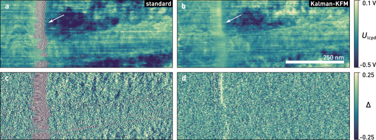
In Figure 10, we compare the performance of our Kalman-KFM controller with a standard integral controller. Both controllers are tuned for optimised closed-loop performance on the nanowire. The integral controller exhibits ringing artefacts at electrode edge, indicated by an arrow in Figure 10a, since the gain margin of the controller is exceeded due to the increased C''. Such feedback oscillations should be avoided particularly in single-scan techniques, because they may perturb the topography controller. Next to the nanowire, where C'' is slightly reduced because of the gate oxide, the bandwidth of the feedback loop drops due to a lower gain.
Figure 10.
a), b) Kelvin and c), d) error signal of an InAs nanowire similar to the device shown in Figure 9, measured with a standard integral controller, a) & c), and the Kelvin observer, b) & d). Feedback oscillations, as indicated by the arrow, are absent in the Kalman control scheme, while the standard deviation of the error signal also decreases from 0.19 to 0.13. (Scan parameters: Afree = 11.2 nm, Aset = 9.6 nm, Q = 500, k = 35 N/m, f0 = 304.5 kHz, fm = 4 kHz, Uac = 2 V, fcut = 50 Hz, n = 4, vtip = 250 nm/s; all images show raw data).
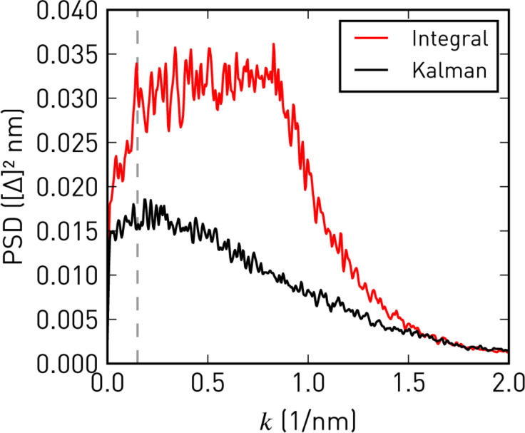
As shown in Figure 10b, with the Kalman-KFM controller the feedback performance and image quality remain consistent during the scan. The error signal (Xω) is almost feature-less and its standard deviation reduces by about 30% on average (excluding edge effects). Better tracking is also apparent from the power spectral densities of the error signals, depicted in Figure 11. For given lock-in filter bandwidths, the Kalman-KFM controller can nullify the ±ωm sidebands faster and better than the integral controller, without adding to the noise level or introducing feedback artefacts.
Figure 11.
One-dimensional power spectral densities of the error signals in Figure 10c,d. Integral feedback works well at low spatial frequencies, k, but is unable to follow higher-frequency modulations. Kalman-KFM control consistently shows a lower error signal at all frequencies. In both cases the roll-off at high k is due to the Kelvin lock-in bandwidths.
Conclusion
We have demonstrated a novel feedback controller for high resolution, frequency modulated Kelvin probe force microscopy. Based on Kalman filtering and stochastic optimal control, our feedback employs a model-driven estimation process, which allows one to integrate sensitivity information from the 2ωm sidebands. In comparison to normalisation approaches [34], this strategy does not increase the noise level.
We have tested performance on an InAs nanowire device with rough surface and abrupt height variations, which pose severe challenges to both traditional single-scan and lift-mode FM-KFM setups. Since direct sideband demodulation allowed us to perform FM-KFM irrespective of the topography feedback, we could perform these scans with amplitude modulation in air. Similarly, Magonov and Alexander [46] demonstrated a setup in which the modulated force gradients are detected from the phase output of the carrier oscillation lock-in, requiring ωm to be within its bandwidth. With direct sideband detection, the detour via a phase modulation is avoided, and ωm can be chosen independently of the lock-in bandwidth to achieve best separation from topography.
We have provided a detailed quantitative description of the evolution of sidebands in dynamic AFM modes. Precise knowledge of their frequency dependence in low and high Q environments is not only neccessary for accurate open-loop KFM techniques, but also offers a direct approach to noise performance and optimisation of frequency modulated KFM [19]. For example, ωm should ideally be chosen below the thermal noise limited bandwidth of the cantilever [24], but the modulation induced by rough surfaces as well as the desired scan bandwidth establish lower limits. Furthermore, the sideband transfer function explains the higher resolution obtained by heterodyne amplitude-modulated KFM [47]. In this technique, the cantilever is driven mechanically at ω0 and electrically at ωm = ω1 − ω0, where ω0 and ω1 are the lowest two eigenfrequencies of the cantilever. Accordingly, the sideband at ω0 + ωm coincides with the second eigenmode of the cantilever, resulting in an amplified signal proportional to the electrostatic force gradient instead of the electrostatic force.
Although we have found our feedback loop superior to existing controllers, we see several aspects for improvement in the future. For example, the dynamics of Ulcpd are currently modelled as white noise. Since successive lines in AFM scans only change slightly, information from the previous line could be incorporated, similar to a feed-forward controller [29]. Other state estimators could also be integrated, including H-∞ filters for minimising the worst-case error [42].
Finally, we would like to point out that using our Kalman-KFM controller is not complicated. Since it automatically incorporates the lock-in filter settings and the system sensitivity, the only parameters left to tune are the noise power spectral density of the Ulcpd transitions and sideband observations. Because the latter is easily determined from a power spectrum near the sidebands, the controller performance can be tuned in practice using the transition noise only. Independent of the chosen parameters, the feedback loop will be stable thanks to the Kalman filter structure.
Supporting Information
Detailed derivations of the effective forces and the state-space KFM controller.
Acknowledgments
The authors thank Daniel Wright (Zurich Instruments) for his assistance with the real-time programming interface, and Romain Stomp (Zurich Instruments) for many stimulating discussions as well as joint first experiments on the frequency dependence of the sidebands. InAs nanowire fabrication was facilitated by Siegfried Karg and Ute Drechsler (IBM). We gratefully acknowledge financial support from the Swiss National Science Foundation (Project No. 134777).
This article is part of the Thematic Series "Advanced atomic force microscopy techniques IV".
Contributor Information
Tino Wagner, Email: tiwagner@ethz.ch.
Andreas Stemmer, Email: astemmer@ethz.ch.
References
- 1.Weaver J M R, Abraham D W. J Vac Sci Technol, B. 1991;9:1559–1561. doi: 10.1116/1.585423. [DOI] [Google Scholar]
- 2.Nonnenmacher M, O’Boyle M P, Wickramasinghe H K. Appl Phys Lett. 1991;58:2921. doi: 10.1063/1.105227. [DOI] [Google Scholar]
- 3.Jacobs H O, Knapp H F, Stemmer A. Rev Sci Instrum. 1999;70:1756–1760. doi: 10.1063/1.1149664. [DOI] [Google Scholar]
- 4.Halpern E, Cohen G, Gross S, Henning A, Matok M, Kretinin A V, Shtrikman H, Rosenwaks Y. Phys Status Solidi A. 2014;211:473–482. doi: 10.1002/pssa.201300302. [DOI] [Google Scholar]
- 5.Koren E, Berkovitch N, Azriel O, Boag A, Rosenwaks Y, Hemesath E R, Lauhon L J. Appl Phys Lett. 2011;99:3511. doi: 10.1063/1.3665182. [DOI] [Google Scholar]
- 6.Fuller E J, Pan D, Corso B L, Gul O T, Collins P G. Phys Rev B. 2014;89:245450. doi: 10.1103/PhysRevB.89.245450. [DOI] [Google Scholar]
- 7.Ziegler D, Gava P, Guttinger J, Molitor F, Wirtz L, Lazzeri M, Saitta A M, Stemmer A, Mauri F, Stampfer C. Phys Rev B. 2011;83:235434. doi: 10.1103/PhysRevB.83.235434. [DOI] [Google Scholar]
- 8.Wagner T, Köhler D, Milde P, Eng L M. Appl Phys Lett. 2013;103:023102. doi: 10.1063/1.4813076. [DOI] [Google Scholar]
- 9.Jacobs H O, Leuchtmann P, Homan O J, Stemmer A. J Appl Phys. 1998;84:1168. doi: 10.1063/1.368181. [DOI] [Google Scholar]
- 10.Ziegler D, Stemmer A. Nanotechnology. 2011;22:075501. doi: 10.1088/0957-4484/22/7/075501. [DOI] [PubMed] [Google Scholar]
- 11.Strassburg E, Boag A, Rosenwaks Y. Rev Sci Instrum. 2005;76:083705. doi: 10.1063/1.1988089. [DOI] [Google Scholar]
- 12.Cohen G, Halpern E, Nanayakkara S U, Luther J M, Held C, Bennewitz R, Boag A, Rosenwaks Y. Nanotechnology. 2013;24:295702. doi: 10.1088/0957-4484/24/29/295702. [DOI] [PubMed] [Google Scholar]
- 13.Sadewasser S, Lux-Steiner M C. Phys Rev Lett. 2003;91:266101. doi: 10.1103/PhysRevLett.91.266101. [DOI] [PubMed] [Google Scholar]
- 14.Ziegler D, Rychen J, Naujoks N, Stemmer A. Nanotechnology. 2007;18:225505. doi: 10.1088/0957-4484/18/22/225505. [DOI] [Google Scholar]
- 15.Albrecht T R, Grütter P, Horne D, Rugar D. J Appl Phys. 1991;69:668. doi: 10.1063/1.347347. [DOI] [Google Scholar]
- 16.Kitamura S, Iwatsuki M. Appl Phys Lett. 1998;72:3154–3156. doi: 10.1063/1.121577. [DOI] [Google Scholar]
- 17.Kitamura S, Suzuki K, Iwatsuki M. Appl Surf Sci. 1999;140:265–270. doi: 10.1016/S0169-4332(98)00538-8. [DOI] [Google Scholar]
- 18.Hudlet S, Saint Jean M, Guthmann C, Berger J. Eur Phys J B. 1998;2:5. doi: 10.1007/s100510050219. [DOI] [Google Scholar]
- 19.Diesinger H, Deresmes D, Mélin T. Beilstein J Nanotechnol. 2014;5:1–18. doi: 10.3762/bjnano.5.1. [DOI] [PMC free article] [PubMed] [Google Scholar]
- 20.Zerweck U, Loppacher C, Otto T, Grafström S, Eng L M. Phys Rev B. 2005;71:125424. doi: 10.1103/PhysRevB.71.125424. [DOI] [Google Scholar]
- 21.Giessibl F J. Appl Phys Lett. 2001;78:123. doi: 10.1063/1.1335546. [DOI] [Google Scholar]
- 22.Giessibl F J. Phys Rev B. 1997;56:16010. doi: 10.1103/PhysRevB.56.16010. [DOI] [Google Scholar]
- 23.Carlson A B, Crilly P B. Communication Systems. 5th ed. New York, NY, U.S.A.: McGraw Hill; 2009. [Google Scholar]
- 24.Lübbe J, Temmen M, Rode S, Rahe P, Kühnle A, Reichling M. Beilstein J Nanotechnol. 2013;4:32–44. doi: 10.3762/bjnano.4.4. [DOI] [PMC free article] [PubMed] [Google Scholar]
- 25.Martin Y, Abraham D W, Wickramasinghe H K. Appl Phys Lett. 1988;52:1103. doi: 10.1063/1.99224. [DOI] [Google Scholar]
- 26.Abraham D W, Williams C, Slinkman J, Wickramasinghe H K. J Vac Sci Technol, B. 1991;9:703–706. doi: 10.1116/1.585536. [DOI] [Google Scholar]
- 27.Kou L, Ma Z, Li Y J, Naitoh Y, Komiyama M, Sugawara Y. Nanotechnology. 2015;26:195701. doi: 10.1088/0957-4484/26/19/195701. [DOI] [PubMed] [Google Scholar]
- 28.Sadewasser S, Carl P, Glatzel T, Lux-Steiner M C. Nanotechnology. 2004;15:S14–S18. doi: 10.1088/0957-4484/15/2/004. [DOI] [PubMed] [Google Scholar]
- 29.Ziegler D, Naujoks N, Stemmer A. Rev Sci Instrum. 2008;79:063704. doi: 10.1063/1.2947740. [DOI] [PubMed] [Google Scholar]
- 30.Efimov A, Cohen S R. J Vac Sci Technol, A. 2000;18:1051. doi: 10.1116/1.582472. [DOI] [Google Scholar]
- 31.Barbet S, Popoff M, Diesinger H, Deresmes D, Théron D, Mélin T. J Appl Phys. 2014;115:144313. doi: 10.1063/1.4870710. [DOI] [Google Scholar]
- 32.Sadewasser S, Glatzel T, editors. Kelvin Probe Force Microscopy. Berlin, Germany: Springer; 2012. [Google Scholar]
- 33.Polak L, de Man S, Wijngaarden R J. Rev Sci Instrum. 2014;85:046111. doi: 10.1063/1.4873331. [DOI] [PubMed] [Google Scholar]
- 34.Lee M, Lee W, Prinz F B. Nanotechnology. 2006;17:3728–3733. doi: 10.1088/0957-4484/17/15/019. [DOI] [Google Scholar]
- 35.Ziegler J G, Nichols N B. Trans ASME. 1942;64:759–765. [Google Scholar]
- 36.Bechhoefer J. Rev Mod Phys. 2005;77:783–836. doi: 10.1103/RevModPhys.77.783. [DOI] [Google Scholar]
- 37.Friedland B. Control System Design: An Introduction to State-Space Methods. Mineola, NY, U.S.A.: Dover Publications, Inc.; 2005. [Google Scholar]
- 38.Degen C L, Meier U, Lin Q, Hunkeler A, Meier B H. Rev Sci Instrum. 2006;77:043707. doi: 10.1063/1.2183221. [DOI] [Google Scholar]
- 39.Schitter G, Menold P, Knapp H F, Allgöwer F, Stemmer A. Rev Sci Instrum. 2001;72:3320–3327. doi: 10.1063/1.1387253. [DOI] [Google Scholar]
- 40.Kalman R E. J Basic Eng. 1960;82:35–45. doi: 10.1115/1.3662552. [DOI] [Google Scholar]
- 41.Kalman R E, Bucy R S. J Basic Eng. 1961;83:95–108. doi: 10.1115/1.3658902. [DOI] [Google Scholar]
- 42.Simon D. Optimal State Estimation. New York, NY, U.S.A.: Wiley-Interscience; 2006. [Google Scholar]
- 43. [Aug 9;2015 ];Eigen v3. Available from: http://eigen.tuxfamily.org.
- 44.Sulchek T, Hsieh R, Adams J D, Yaralioglu G G, Minne S C, Quate C F, Cleveland J P, Atalar A, Adderton D M. Appl Phys Lett. 2000;76:1473–1475. doi: 10.1063/1.126071. [DOI] [Google Scholar]
- 45.Hölscher H, Schwarz U D. Int J Non-Linear Mech. 2007;42:608–625. doi: 10.1016/j.ijnonlinmec.2007.01.018. [DOI] [Google Scholar]
- 46.Magonov S, Alexander J. Beilstein J Nanotechnol. 2011;2:15–27. doi: 10.3762/bjnano.2.2. [DOI] [PMC free article] [PubMed] [Google Scholar]
- 47.Sugawara Y, Kou L, Ma Z, Kamijo T, Naitoh Y, Jun Li Y. Appl Phys Lett. 2012;100:223104. doi: 10.1063/1.4723697. [DOI] [Google Scholar]
Associated Data
This section collects any data citations, data availability statements, or supplementary materials included in this article.
Supplementary Materials
Detailed derivations of the effective forces and the state-space KFM controller.


