Abstract
This paper considers the semi-automated robotic surgical procedure for removing the brain tumor margins, where the manual operation is a tedious and time-consuming task for surgeons. We present robust path planning methods for robotic ablation of tumor residues in various shapes, which are represented in point-clouds instead of analytical geometry. Along with the path plans, corresponding metrics are also delivered to the surgeon for selecting the optimal candidate in the automated robotic ablation. The selected path plan is then executed and tested on RAVEN™ II surgical robot platform as part of the semi-automated robotic brain tumor ablation surgery in a simulated tissue phantom.
I. Introduction
In the last few decades, enormous technical developments in computer science, engineering as well as the advanced medical imaging techniques have greatly improved the possibilities for complex robotic assisted neurosurgery, where the complexity and high sensitivity of the anatomical regions requires fine precision and dexterity [1], [2]. In this study, we consider the robotic automation of a surgical subtask in brain tumor ablation surgery, i.e. removal of cancerous margin, under surgeon’s supervision.
A. Clinical Scenario
Complete resection of the brain tumors is a extremely critical factor for patient’s survival rate and life quality. A retrospective study of more than 400 patients with glioblastoma showed significantly longer survival times for patients with resection of 98 % or more of the tumor volume than for those with a lesser extent of resection [3]. In the proposed surgical scenario, it is assumed a surgical cavity with possible cancerous material on its wall will be exposed after manual removal of the bulk brain tumor by surgeon. The proposed surgical task is clean-up of the tumor margins in the surgical cavity.
The modern biomarker-’Tumor paint’ [4], that selectively binds to the tumor cells and fluoresces with illumination of the conjugated dye, will be applied for detecting the tumor margins under a fluorescence-based imaging system using a 1.6mm diameter Scanning Fiber Endoscope (SFE) [5]. The cancerous regions are able to be segmented in the wide-field fluorescence image that is co-registered with color reflectance SFE image. Due to the weak fluorescence responses and long integration time for image collection, manual treatment of the labeled tumor tissue is tedious and requires high precision cutting over long duration. Thus, this medical procedure becomes an ideal candidate for the automated robotic task.
B. Preliminary Study
1) Three-dimensional virtual reconstruction of a surgical cavity
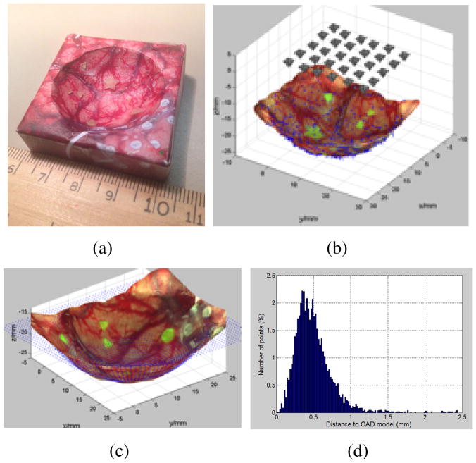
Gong et al. [6] showed the feasibility of the 3D image reconstruction of a surgical cavity using a set of 2D images taken from SFE (Figure 1).
Fig. 1.
The 3D reconstruction of a spherical tumor cavity phantom with surgical image and residual fluorescence tumor targets. (a). A 3d printed phantom with texture of brain surgery photo glued on its surface. (b) Image sampling grid 5×6 above phantom. (c) The comparison of reconstructed 3D model to the CAD model, shown as blue point cloud. (d). The ICP error between the reconstructed model and the CAD design. 96.3% of all the error values locate in the range of [0–1] mm.
2) Behavior Tree framework for autonomous robotic medical procedure
The potential utility of Behavior Tree (BT) as a modeling language for intelligent robotic surgical procedures was explored in [7]. A BT representation of the semi-automated brain tumor ablation was demonstrated for simplified planar geometry and software integration was implemented.
C. Technical Aspect
This paper is built upon the above preliminary work and discusses an intermediate step towards the planned intelligent robotic surgical system that will scan the cavity for fluorescently labeled tissue exposed by bulk tumor removal, and automatically treat that material. This procedure will be repeated until no cancerous tissue is found. Particularly in this paper, we present a path planner for this surgical procedure.
Given the tumor segmentation map generated from 3D image reconstruction, our planner will synthesize paths which completely cover the segmented area subject to medical constraints:
Complete removal of all labeled tissue.
Minimize the removal of normal tissue.
The tumor margin is assumed to be homeomorphic to a sphere (that is have no holes) but is likely to have tendrils which will require specialized plans.
A surgeon must have reliable control and choose the trusted plan for robotic treatment.
The obtained 3D segmentation map is represented as a point-cloud, which is relatively smooth on the surface due to the fitting algorithm in reconstruction, however, can vary in geometrical shape and size. To deal with the geometrical irregularity, our proposed complete coverage path planner provides different types of paths based on the analysis of size and shape. Three main types of path pattern are used in planning: zig-zag, contour-parallel, and a mixed pattern of both depending on geometry analysis.
Along with the generated path plans, the path planner also computes the number of tool retractions (when multiple paths of a plan are found), the total number of via-points, as well as an estimated execution time of each plan. This path information will be delivered to the surgeon to decide the most reliable path plan.
We integrate the path planner with the existing BT framework and test the selected plan on the RAVEN™ II surgical robotic system [8]. In this paper, we attempt to provide a systematic approach for surgical coverage path planning.
II. Related Work
A. Path planning in robot-assisted medical procedure
Most of the path planing in robot-assisted surgery is focused on 1) minimizing the tool path length and 2) avoiding the collision with the vital tissue when approaching to target.
In recent years, motion planning for robotic needle steering is one of the most intensively studied examples in medical procedures including tissue biopsies, tumor ablation and brachytherapy cancer treatment. Alterovitz et al. [9], [10] developed a motion planning algorithm for flexible needle steering that considers the uncertainty in robotic motion to maximizing the the probability of avoiding collisions and reaching the target. Durham et al. [11] presented a 3D constant-time motion planning algorithm for steerable needle using inverse kinematics. Jackson [12] proposed a path planner for autonomous robotic suturing that aimed to minimize the interaction forces between the tissue and needle. Bernardes et al.’s [13] method enabled a closed-loop re-planning strategy for dynamic scenes.
Other related planning in medical fields includes minimally invasive surgery, where the optimal port placement and pose planning of the robot are discussed [14], and also in virtual endoscopy, where the optimal guidance path for endoscopic exploration of 3D medical images is computed [15].
B. Analogy to the industrial task
The proposed intra-operative path planning in this study is related to the tool-path planning from point-clouds emerging from the reverse engineering in manufacturing. In this case, the point-cloud is obtained by a scanning system from existing physical profiles, such as sculptures. Traditional approaches are available by reconstructing the CAD model from point-clouds [16]. But those procedures are computationally inefficient and also require the interaction with users with advanced knowledge of surface modeling [17]. Alternative methods without surface reconstruction include Z-map modeling [18], 3D biarc fitting [19] and moving least-square surfaces [20]. Unlike the above methods which mainly emphasize the surface uncertainty, our approach is focused on dealing with contour/shape irregularity.
III. Problem Definition and Assumptions
Terminology: Terms used throughout this paper are defined here for clarity.
Surgical cavity: is a concave cavity that is exposed after the manual removal of the brain tumor, which can grow up to a golf ball size.
Tumor margin: represents the tumor residue that remains on the surface of the surgical cavity after major removal. Tumor margins can be in any shapes and sizes.
Assumption: In this work, we assume that 1) all tumor margins are homeomorphic to a sphere, i.e. there are no holes in each tumor margin. 2) All cancerous tissue remains on the surface of the surgical cavity, although it is possible in real clinical case that the tendrils may go deeply into brain tissue. 3). The surgical cavity is close to an inverted shallow spherical dome, but its inner surface can be rough.
Problem Statement: The objective of the path planner addressed in this paper is to find complete coverage path plans given a 3D segmentation map of each tumor margin detected in the surgical cavity. More precisely speaking, we are given a set of points Pc that represent the contour of a tumor margin and a set of points Ps that describe the inner surface geometry of that margin, as well as a minimum circular treatment area At of the surgical tool. Our goal is to deliver at least one and a finite set of possible path plans S that cover the entire margin area for robotic ablation.
| (1) |
where S ≠ Ø, 0 < |S| ≤ n, n is an integer as the maximal number of plans. (n = 3 for current version of the planner)
IV. Complete Coverage Path Planning with Geometry Irregularity
A. Guidance Plane and Shape Factor
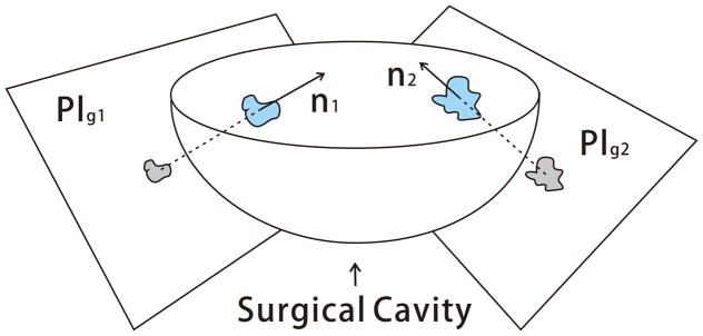
The remaining tumor margin after the major removal could be represented in any arbitrary geometry and size. By assumption, the tumor margins stay on the surface of the surgical cavity, thus we define a guidance plane called Plg such that the projection of the point-cloud Pc onto Plg preserves the shape similarity. In this study, to get the maximal shape similarity, the guidance plane is chosen as the plane perpendicular to the surface normal of each tumor margin. The surface normal is computed as the average of point normals using PCL [21]. Figure 2 describes the guidance plane Plg of each tumor margin in the surgical cavity.
Fig. 2.
Illustration of the guidance plane and surgical cavity
The projection generates a set of 2D points Pproj with respect to the plane Plg. The shape analysis is performed upon the polygonal approximation of the point set Pproj. Shape characterization [22], [23] is a large area of image analysis, even a brief review is beyond the scope of this paper. In this paper, we focus on the analysis of the shape irregularity, i.e. shapes that have irregular, asymmetric and serrated edges, as most of the brain tumor margins.
Circularity is chosen for overall evaluation of the shape irregularity and is described by Eq.(2).
| (2) |
where P is the perimeter of the polygon consisting of Pproj, A is the corresponding area computed using Green’s Theorem, derived as Eq.(3).
| (3) |
where n = |Pproj|, (xk, yk) is the k-th point of Pproj in counter-clockwise order, and (xn, yn) = (x0, y0)
It is obvious that the circularity of a circle is 1, and much less than one for an irregular shape. Circularity determines the path patterns that will be used in planning. Another key measurement is the enclosed area A of the boundary Pproj, which determines the maximal number of plans delivered to surgeon as final solutions.
B. Flowchart
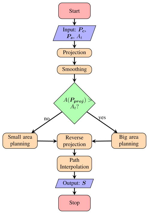
We divide our planning algorithm into five major steps: 1) projection onto the guidance plane, 2) smoothing, 3) 2D coverage path planning on the guidance plane, 4) reverse projection onto the original 3D surface formed by point-cloud, and 5) path interpolation on 3D surface. The planning flowchart is described in Figure 3. The path planning algorithms are further divided into two basic groups based on the area of the shape for improving the efficiency of robotic execution and reducing the removal of healthy tissue.
Fig. 3.
Flowchart of the path planner
C. Planning with Shape Irregularity - small area
The small area shape is defined as a polygon consisting of Pproj whose area is no larger than the minimal treatment area, i.e. A(Pproj) ≤ At. At is defined as the minimum area cleaned by the surgical probe when approaching to the tissue surface, and is approximated as a circle in this study.
The coverage rate of a minimum treatment area is defined as the percentage of the Ps that is located within the minimum treatment circle co-centered with Pproj. The path plan of the tumor margin with small area is determined by the coverage rate as described in Algorithm 1.
Algorithm 1.
Small area path generation
| Require: Pc ≠ Ø, Ps ≠ Ø, At ≥ A(Pproj) > 0 | |
| 1: | if coverage rate ≥ 95% then |
| 2: | Psmall ← centroid of Pproj |
| 3: | else |
| 4: | Psmall ← Pproj |
| 5: | end if |
| 6: | return Psmall |
D. Planning with Shape Irregularity - big area
The big area shape is classified as a polygon consisting of Pproj that its area is larger than the minimal treatment area At, i.e. APproj > At. We explore three possible types of plan for each big area shape: zigzag, contour-parallel and mixed pattern of both.
Zigzag and contour-parallel are very common path patterns used in industrial CNC pocket milling. Here, we discuss the similarity and difference compared to industrial applications. The major difference is that in CNC machining, pocket’s contour is well defined as arcs, lines using CAD/CAM, while in this work, the tumor’s contour is defined as a set of points derived from image processing. The contour in this case can be much noisier even after smoothing than the industrial case. Although a certain level of smoothing is performed before planning, it is not wise to filter out all noise that is potentially tumor cells. Our proposed algorithms are able to robustly deal with edge noise and avoid numerical error.
1. Zigzag path planning is computationally the most efficient algorithm among above mentioned plans, although this plan sometimes generates inefficient paths for robotic execution. When dealing with very irregular shapes, such as shapes with tendrils, multiple tool retractions are required. Our proposed Algorithm 2 for zigzag planning is based on the traditional zigzag planning [24] with modifications to fit our application.
Algorithm 2.
Zigzag path generation
| Require: Pc ≠ Ø, Ps ≠ Ø, A(Pproj) > At > 0 | ||
| 1: |
|
|
| 2: | Mc ← construction of monotone chains along sweeping direction from Pproj | |
| 3: | Pinters ← intersection points between Mc and parallel offsetting lines. | |
| 4: | Pz ← sorting of Pinters into zigzag pattern | |
| 5: | return Pz | |
According to the ray casting algorithm, the intersection points computation normally generates an even number n of points and n−1 path segments on each parallel offset line. The middle point of each path segment lies alternately inside and outside of the polygon. However, numerical problems may occur in finite precision arithmetics such that any of the above criteria are violated. Thus, the validity of the generated intersection points is checked based on both criteria mentioned above. An extra neighboring point with 0.2mm distance is inserted when an invalid intersection point is found.
In the sorting part, we first group all intersection points into two parts: “in” and “out”. As illustrated in Figure 4, an “in” point has an odd index number and is the starting point for an imaginary ray entering into the polygon. An “out” point has an even index number and is where the imaginary ray leaving the polygon.
Fig. 4.
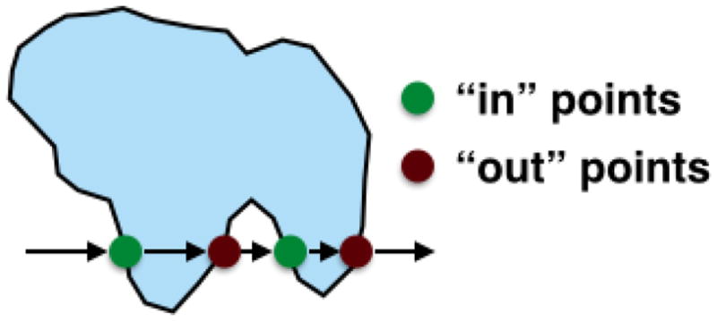
Definition of an “in’ points and “out” point
The sorting of intersection points follows five steps:
step 1. Find “in” point of the lowest row as the starting point of a sub-path:
step 2. If not found, stop, path generation finished.
step 3. Append neighboring “in/out” point to form ’zigzag’ pattern.
step 4. Find closest same group point of the next row and go to step 3.
step 5. Delete visited points, go to step 1 to create a new sub-path.
2. Contour-parallel path planning uses a series of offsetting contours to cover the tumor margin. Although the computation time is longer than zigzag planning, the contour-parallel path cleans the serrated edges better. The computation of the offset contour is using the clipper library [25] which is based on Vatti’s clipping algorithm [26]. The pseudocode is described below.
Algorithm 3.
Contour parallel path generation
| Require: Pc ≠ Ø, Ps ≠ Ø, A(Pproj) > At > 0 | |
| 1: | , Pp ← Ø |
| 2: | while Coffset ≠ Ø do |
| 3: | Coffset ← deflation of Coffset by doffset |
| 4: | Pp ← Coffset ∪ Pp |
| 5: | end while |
| 6: | return Pp |
3. Mixed pattern path planning combines the merits of zigzag and contour-parallel planning to deliver the most efficient ablation path for robotic execution: accurate contour following and fast ablation of inner material. The mixed pattern planning is designed to deliver the most efficient path for star-shaped tumor margins, e.g. tumor margin with tendrils. Although for some shapes, such as long ellipse-like shapes, the mixed pattern planning may result in the same path as the contour-parallel planning.
Algorithm 4.
Mixed pattern path generation
| Require: Pc ≠ Ø, Ps ≠ Ø, A(Pproj) > At > 0 | ||
| 1: |
|
|
| 2: | Coffset ← Pproj, Pm ← Coffset | |
| 3: | while Coffset ≠ Ø && fcirc(Coffset) < fcircmin do | |
| 4: | Coffset ← deflation of Coffset by doffset | |
| 5: | Pm ← Coffset ∪ Pm | |
| 6: | end while | |
| 7: | if Coffset ≠ Ø then | |
| 8: | if A(Coffset) > At then | |
| 9: | Plast ← zigzag path generation | |
| 10: | else | |
| 11: | Plast ← small area path generation | |
| 12: | end if | |
| 13: | Pm ← Plast ∪ Pm | |
| 14: | end if | |
| 15: | return Pm | |
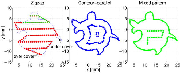
Figure 5 shows the generated 2D paths on the guidance plane for an irregular shape. Both contour-parallel and mixed pattern covers the contour exactly. But for the zigzag pattern there exist over-cover and under-cover of the contour, which indicates more healthy tissue and not all tumor tissue will be removed.
Fig. 5.
2d path on guidance plane using three path patterns.
E. Reverse Projection and Path Interpolation
Finally, the generated 2D path via-points are projected back onto the original surface of point-cloud. For each 2D point, a search circle of radius 0.5mm is used for computation of the depth using a weighted average of all points inside the circle. If no points in found inside the circle, the depth of the closest point is adopted. Linear path interpolation is performed on the 3D surface such that the distance between each pair of neighboring points is no greater than 1mm.
F. Path Plan Display
The final path plans S are represented in a set of via-points in 3D. Each plan are displayed on terminal with total number of via-points nv for each plan, number of tool retractions nr and the estimated executing time which is roughly proportional to nv based on the previous study.
V. Experiment and Results
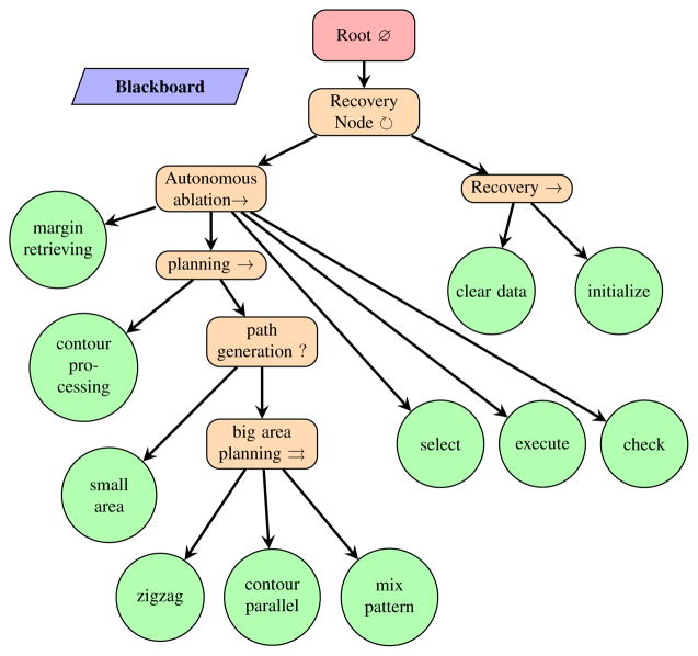
To demonstrate the validity of the planning algorithms, we integrated the proposed path planner into the existing behavior tree framework for semi-autonomous robotic brain tumor ablation as depicted in Figure 6. We designed an experimental surgical environment and used RAVEN™ II surgical robot to carry out the generated robotic ablation task. Performance of each plan is compared and analyzed.
Fig. 6.
Behavior Tree [27] representation of the semi-autonomous robotic ablation procedure. Recovery Node is implemented in [7]
A. Testbed
1) Surgical Field
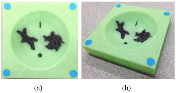
A 3D printed surgical field phantom (60mm x 60mm) was used in this experiment as shown in Figure 7. Each corner was marked with a colored dot for registration of the surgical field into the stereo-tracking system. The surgical cavity was designed as an inverted spherical dome with a spherical radius of 40mm. The diameter of the cavity was 55mm. To validate the robustness of the proposed path planner, irregular shaped indentations were printed for holding the iron fillings that represent tumor cells.
Fig. 7.
Simulated surgical cavity after major removal of brain tumor. (a). top view (b). perspective view.
2) RAVEN™ II Surgical Robot and Ablation System
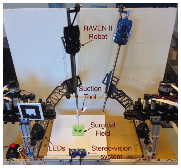
The simulated ablation was performed on RAVEN™ II open-source surgical robotic platform with stereo-vision augmentation (Figure 8). A surgical suction system with its tip marked in red was attached to one of the robotic arm. The 2mm diameter suction tool clears approximately a 6mm diameter circle under 200 mmHg vacuum pressure. This simulates the mechanism of an ultrasonic surgical aspirator which removes soft tumor tissue in contact with the tip of an ultrasonic horn (3-mm diameter) with saline suction [28]. The tip position was tracked by stereo-vision system for closed-loop position control. In the designed experiment, the robot should automatically clean up the iron filling using generated path plans.
Fig. 8.
System setup for semi-automated robotic ablation in simulated surgical field.
B. Results and Discussion
1) Plan Generation
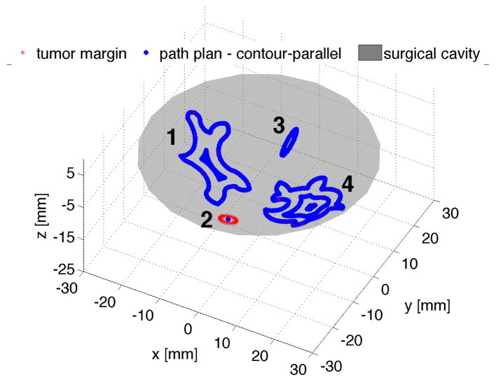
Our planner was able to generate coverage path plans for each tumor margin illustrated in the tissue phantom. Figure 9 shows the contour-parallel path plan for the bigger tumor margin 1 and 4, and small area plan for margin 2 and 3 when a minimum treatment area At of 32π mm2 is chosen.
Fig. 9.
Planning results (contour-parallel for bigger tumor margins)
The path planner also generates multiple plans for tumor margin 1 and 4. Table I and II list the computed metrics for surgeon’s reference. It is indicated in Table I, both contour parallel and mixed pattern planner generate the same path plans for tumor margin 1, because the circularity of the offsetting contours is too small to perform the zigzag planning. For tumor margin 4 in Table II, the mixed patten planner delivers the plan with fewer tool retractions and fewer via-points numbers compared to the contour parallel planner, since the offsetting contour of margin 4 is “regular” enough to perform zigzag planning.
TABLE I.
Plans comparison of tumor margin 1
| zigzag | contour-parallel | mixed pattern | |
|---|---|---|---|
| number of via-points | 98 | 135 | 135 |
| number of tool retractions | 1 | 1 | 1 |
| estimated robot executing time | 118 s | 166 s | 166s |
TABLE II.
Plans comparison of tumor margin 4
| zigzag | contour-parallel | mixed pattern | |
|---|---|---|---|
| number of via-points | 120 | 164 | 145 |
| number of tool retractions | 1 | 2 | 1 |
| estimated robot executing time | 154 s | 233 s | 174 s |
2) Computation Time
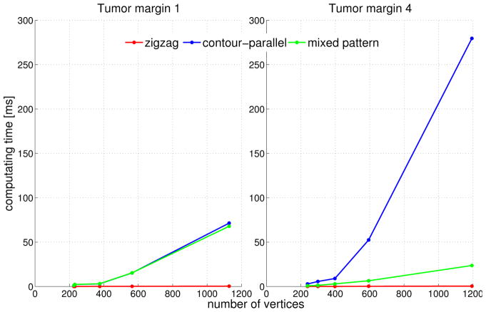
The computation time of each plan based on an average of 30 runs on a machine with 4GB RAM and Intel Core™2 Quad cpu@2.5Ghz is compared in Figure 10.
Fig. 10.
Computation time in mili-second using different path patterns of two bigger tumor margins
Figure 10 indicates the computation complexity for each path pattern. The computation time using contour-parallel pattern increases dramatically with the increase of the number of vertices and shape complexity. The computation time of zigzag path is extremely fast and increases quasi linearly with the number of vertices. For some margins with serrated edges, such as tumor margin 4, the mixed pattern planning is able to reduce the computation time remarkably compared to contour parallel planning (Figure 10-right), while for some margins with long and narrow shape like tumor margin 1, mixed pattern and contour-parallel planning result in the same plan (Figure 10-left).
3) Path Execution
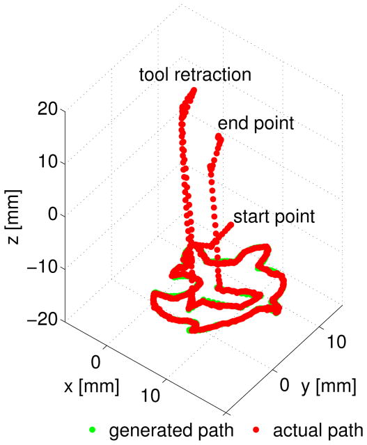
Each of the generated path plan was executed by the robot for performance analysis. To avoid direct contact between the phantom and suction tool, we applied a virtual surface constraint 3mm above the tumor margins. All path plans cleaned up the iron filling thoroughly. The suction tool tip position was tracked at 7.5 Hz using stereo-vision system during the robotic ablation. Figure 11 indicates the robot follows the generated path plan within a desired error boundary.
Fig. 11.
Robot path and designed mixed pattern path for tumor margin 4 in surgical field frame
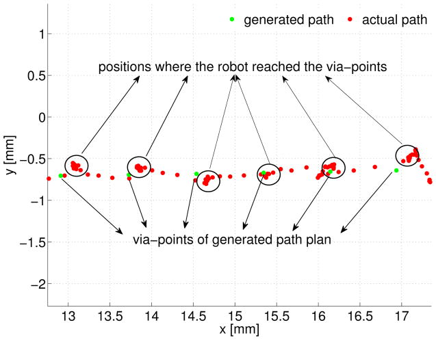
An enlarged display of each via-point and the robot tip position is presented in Figure 12. The RMS error between the actual path and generated path displayed in Figure 11 is computed as 0.207 mm in 3D space.
Fig. 12.
Motion error analysis on xy plane of surgical field frame
The spatial error during the robotic ablation mainly results from two parts: 1) positioning threshold set in the robot motion control. 2) tracking noise of the vision system. Smaller threshold leads to better positioning accuracy. However, reducing the threshold may cause the instability in motion control. In this experiment, a threshold of 0.4mm is chosen for achieving a balance between stability and performance, because this distance is smaller than the distance between two neighboring via-points, but is bigger than the precision of the vision tracking system.
VI. Conclusion and Future Work
In this paper, we presented a 3D complete coverage path planner as part of the large project of semi-automated image-guided robotic brain tumor ablation. The proposed planner was integrated into an existing BT framework as top-level automated decision making. We tested and analyzed generated plans executed by RAVEN™ II surgical robot with stereo-vision tracking, although the surgeon will still need to decide a plan before robotic execution.
Our future work will focus on exploration of a more realistic surgical cavity that is not an spherical dome and the inner surface has possibly not been smoothed. More complete system integration of SFE and surgical robot will be the next major step towards a final intelligent medical robotic system. Furthermore, the stereo-vision may lose the tracking ability during the ablation inside a deep cavity. In this case, the pose estimation of surgical tool tip from the SFE image [29] will play a key role for robot motion guidance.
Acknowledgments
This work is supported by the U.S National Institutes of Health NIBIB R01 EB016457 NRI-Small. The authors appreciate Angelique Berens MD for providing surgical suction equipments.
Contributor Information
Danying Hu, Email: danying@uw.edu.
Yuanzheng Gong, Email: gong7@uw.edu.
Blake Hannaford, Email: blake@uw.edu.
Eric J. Seibel, Email: eseibel@uw.edu.
References
- 1.Nathoo N, Çavusoglu MC, Vogelbaum MA, Barnett GH. In touch with robotics: neurosurgery for the future. Neurosurgery. 2005;56(3):421–433. doi: 10.1227/01.neu.0000153929.68024.cf. [DOI] [PubMed] [Google Scholar]
- 2.Haidegger T, Kovacs L, Fordos G, Benyo Z, Kazanzides P. Future trends in robotic neurosurgery. 14th Nordic-Baltic Conference on Biomedical Engineering and Medical Physics; Springer; 2008. pp. 229–233. [Google Scholar]
- 3.Lacroix M, Abi-Said D, Fourney DR, Gokaslan ZL, Shi W, DeMonte F, Lang FF, McCutcheon IE, Hassenbusch SJ, Holland E, et al. A multivariate analysis of 416 patients with glioblastoma multiforme: prognosis, extent of resection, and survival. Journal of neurosurgery. 2001;95(2):190–198. doi: 10.3171/jns.2001.95.2.0190. [DOI] [PubMed] [Google Scholar]
- 4.Veiseh M, Gabikian P, Bahrami SB, Veiseh O, Zhang M, Hackman RC, Ravanpay AC, Stroud MR, Kusuma Y, Hansen SJ, et al. Tumor paint: a chlorotoxin: Cy5. 5 bioconjugate for intraoperative visualization of cancer foci. Cancer research. 2007;67(14):6882–6888. doi: 10.1158/0008-5472.CAN-06-3948. [DOI] [PubMed] [Google Scholar]
- 5.Seibel EJ, Johnston RS, Melville CD. Biomedical Optics 2006. International Society for Optics and Photonics; 2006. A full-color scanning fiber endoscope; pp. 608303–608303. [Google Scholar]
- 6.Gong Y, Hu D, Hannaford B, Seibel EJ. Accurate 3d virtual reconstruction of surgical field using calibrated trajectories of an image-guided medical robot. Journal of Medical Imaging. 2014;1:035002. doi: 10.1117/1.JMI.1.3.035002. [DOI] [PMC free article] [PubMed] [Google Scholar]
- 7.Hu D, Gong Y, Hannaford B, Seibel EJ. Semi-autonomous simulated brain tumor ablation with ravenii surgical robot using behavior tree. Robotics and Automation (ICRA), 2015 IEEE International Conference on; IEEE; 2015. pp. 3868–3875. [DOI] [PMC free article] [PubMed] [Google Scholar]
- 8.Hannaford B, Rosen J, Friedman DW, King H, Roan P, Cheng L, Glozman D, Ma J, Kosari SN, White L. Raven-ii: an open platform for surgical robotics research. Biomedical Engineering, IEEE Transactions on. 2013;60(4):954–959. doi: 10.1109/TBME.2012.2228858. [DOI] [PubMed] [Google Scholar]
- 9.Alterovitz R, Lim A, Goldberg K, Chirikjian GS, Okamura AM. Steering flexible needles under markov motion uncertainty. Intelligent Robots and Systems, 2005.(IROS 2005). 2005 IEEE/RSJ International Conference on; IEEE; 2005. pp. 1570–1575. [Google Scholar]
- 10.Alterovitz R, Siméon T, Goldberg KY. The stochastic motion roadmap: A sampling framework for planning with markov motion uncertainty. Robotics: Science and Systems. 2007;3:233–241. Citeseer. [Google Scholar]
- 11.Duindam V, Xu J, Alterovitz R, Sastry S, Goldberg K. Algorithmic Foundation of Robotics VIII. Springer; 2010. 3d motion planning algorithms for steerable needles using inverse kinematics; pp. 535–549. [DOI] [PMC free article] [PubMed] [Google Scholar]
- 12.Jackson RC, Cavusoglu MC. Needle path planning for autonomous robotic surgical suturing. Robotics and Automation (ICRA), 2013 IEEE International Conference on; IEEE; 2013. pp. 1669–1675. [DOI] [PMC free article] [PubMed] [Google Scholar]
- 13.Bernardes M, Adorno BV, Poignet P, Borges G. Robot-assisted automatic insertion of steerable needles with closed-loop imaging feedback and intraoperative trajectory replanning. Mechatronics. 2013;23(6):630–645. [Google Scholar]
- 14.Adhami L, Coste-Manière È. Optimal planning for minimally invasive surgical robots. Robotics and Automation, IEEE Transactions on. 2003;19(5):854–863. [Google Scholar]
- 15.Paik DS, Beaulieu CF, Jeffrey RB, Rubin GD, Napel S. Automated flight path planning for virtual endoscopy. Medical Physics. 1998;25(5):629–637. doi: 10.1118/1.598244. [DOI] [PubMed] [Google Scholar]
- 16.Lin YP, Wang CT, Dai KR. Reverse engineering in cad model reconstruction of customized artificial joint. Medical Engineering & Physics. 2005;27(2):189–193. doi: 10.1016/j.medengphy.2004.09.006. [DOI] [PubMed] [Google Scholar]
- 17.Varady T, Martin RR, Cox J. Reverse engineering of geometric modelsan introduction. Computer-Aided Design. 1997;29(4):255–268. [Google Scholar]
- 18.Lin AC, Liu HT. Automatic generation of nc cutter path from massive data points. Computer-Aided Design. 1998;30(1):77–90. [Google Scholar]
- 19.Chui K, Chiu W, Yu K. Direct 5-axis tool-path generation from point cloud input using 3d biarc fitting. Robotics and Computer-Integrated Manufacturing. 2008;24(2):270–286. [Google Scholar]
- 20.Zhang D, Yang P, Qian X. Adaptive nc path generation from massive point data with bounded error. Journal of Manufacturing Science and Engineering. 2009;131(1):011001. [Google Scholar]
- 21.Point cloud library. http://pointclouds.org.
- 22.Pavlidis T. A review of algorithms for shape analysis. Computer graphics and image processing. 1978;7(2):243–258. [Google Scholar]
- 23.Loncaric S. A survey of shape analysis techniques. Pattern recognition. 1998;31(8):983–1001. [Google Scholar]
- 24.Park SC, Choi BK. Tool-path planning for direction-parallel area milling. Computer-Aided Design. 2000;32(1):17–25. [Google Scholar]
- 25.Clipper library. http://www.angusj.com/delphi/clipper/documentation/Docs/Overview/_Body.htm.
- 26.Vatti BR. A generic solution to polygon clipping. Communications of the ACM. 1992;35(7):56–63. [Google Scholar]
- 27.Marzinotto A, Colledanchise M, Smith C, Ogren P. Towards a unified behavior trees framework for robot control. Robotics and Automation (ICRA), 2014 IEEE International Conference on; IEEE; 2014. pp. 5420–5427. [Google Scholar]
- 28.Bond L, Cimino W. Physics of ultrasonic surgery using tissue fragmentation. Ultrasonics. 1996;34(2):579–585. doi: 10.1016/0041-624x(96)00039-x. [DOI] [PubMed] [Google Scholar]
- 29.Gong Y, Hu D, Hannaford B, Seibel EJ. SPIE Medical Imaging. International Society for Optics and Photonics; 2015. Toward real-time endoscopically-guided robotic navigation based on a 3d virtual surgical field model; pp. 94150C–94150C. [DOI] [PMC free article] [PubMed] [Google Scholar]


