

Abstract
The spliceosome assembles on a pre‐mRNA intron by binding of five snRNPs and numerous proteins, leading to the formation of the pre‐catalytic B complex. While the general morphology of the B complex is known, the spatial arrangement of proteins and snRNP subunits within it remain to be elucidated. To shed light on the architecture of the yeast B complex, we immuno‐labelled selected proteins and located them by negative‐stain electron microscopy. The B complex exhibited a triangular shape with main body, head and neck domains. We located the U5 snRNP components Brr2 at the top and Prp8 and Snu114 in the centre of the main body. We found several U2 SF3a (Prp9 and Prp11) and SF3b (Hsh155 and Cus1) proteins in the head domain and two U4/U6 snRNP proteins (Prp3 and Lsm4) in the neck domain that connects the main body with the head. Thus, we could assign distinct domains of the B complex to the respective snRNPs and provide the first detailed picture of the subunit architecture and protein arrangements of the B complex.
Keywords: B complex, electron microscopy, immunolabelling, protein localisation, spliceosome
Subject Categories: RNA Biology, Structural Biology
Introduction
Pre‐mRNA splicing is carried out by a large, highly dynamic multi‐MDa protein–RNA complex, termed the spliceosome. On each pre‐mRNA intron, the spliceosome assembles anew by the stepwise recruitment of small nuclear ribonucleoprotein particles (snRNPs) and numerous non‐snRNP proteins (reviewed by Will & Lührmann, 2011). Each snRNP involved in splicing contains the respective snRNA bound to a heteroheptameric Sm ring and additional specific proteins, except for the U6 snRNA, which is bound to seven Sm‐like (Lsm) proteins instead. During the course of spliceosome assembly, the snRNPs bind to the pre‐mRNA in a stepwise manner. The first step is the binding of the U1 snRNP to the 5′ splice site. The next step is the ATP‐dependent binding of the U2 snRNP to the branch‐point sequence (BPS), which results in the formation of the A complex. This binding involves base‐pairing of the U2 snRNA with the BPS, stabilised by protein–protein and protein–RNA interactions involving the heteromeric U2 snRNP subcomplexes SF3a and SF3b (Will & Lührmann, 2011). Next, the U4/U6·U5 tri‐snRNP is stably integrated into the spliceosome resulting in the fully assembled spliceosome (B complex).
In the tri‐snRNP, the U4 and the U6 snRNAs are base‐paired, forming a three‐way junction made up of the U4/U6 stem I, the U4/U6 stem II and the U4 internal stem loop I that is located between stems I and II (Mougin et al, 2002; Will & Lührmann, 2011). The proteins of the tri‐snRNP can be grouped into U5 snRNP proteins, U4/U6 di‐snRNP proteins and additional proteins stably bound only in the tri‐snRNP (Gottschalk et al, 1999; Stevens & Abelson, 1999). Among the U5 snRNP proteins, Prp8, Brr2 and Snu114 are the largest and are important for catalytic activation of the spliceosome (Nielsen & Staley, 2012). The U4/U6 di‐snRNP proteins Prp3 and Prp4 have been shown to interact with the U4 snRNA in stem II (Xu et al, 1990; Nottrott et al, 2002), and Prp31 has been shown to bind to stem loop I (Schultz et al, 2006; Liu et al, 2007). Upon integration of the tri‐snRNP into the spliceosome, the 3′ end of the U6 snRNA base‐pairs with the 5′ end of the U2 snRNA (Madhani & Guthrie, 1992). Recent findings indicate that additional interactions between components of the U2 and the U5 snRNPs contribute to stable tri‐snRNP binding (Hegele et al, 2012). Immediately before or simultaneously with the integration of the tri‐snRNP, the U1 snRNA is destabilised (Staley & Guthrie, 1999). This event frees the 5′ splice site and allows it to base‐pair with the U6 snRNA (Kandels‐Lewis & Séraphin, 1993; Lesser & Guthrie, 1993).
The B complex represents the fully assembled spliceosome; it contains all the snRNPs and additional non‐snRNP protein complexes such as the nineteen complex (NTC) and the retention and splicing (RES) complex composed of Bud13, Snu17 and Pml1 (Dziembowski et al, 2004; Fabrizio et al, 2009). The protein composition of the B complex from Saccharomyces cerevisiae is shown in Fig EV1. The NTC proteins, the RES complex proteins and the U1 snRNP proteins are present in substoichiometric amounts in the yeast B complex as indicated by pale colours in Fig EV1. Although the B complex represents the assembly stage that is committed to splicing, the active site has not yet been formed.
Figure EV1. Protein composition of the spliceosomal B complex from Saccharomyces cerevisiae .
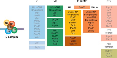
The protein composition of the yeast spliceosomal B complex was determined by mass spectrometry, and the proteins (yeast nomenclature) are grouped according to their snRNP association, function or presence in a stable heteromeric subcomplex (Fabrizio et al, 2009). Full colours indicate proteins present in stoichiometric amounts, while pale colours and grey letters indicate proteins present in substoichiometric amounts. Asterisks mark the proteins that were located in this study. A schematic drawing of the B complex is given on the left.
Activation of the spliceosome involves the action of the RNA‐helicase Brr2 which, regulated by Prp8 (Small et al, 2006; Mozaffari‐Jovin et al, 2012, 2013), unwinds the U4/U6 RNA duplex (Laggerbauer et al, 1998; Raghunathan & Guthrie, 1998; Hahn et al, 2012). Following this event, the spliceosome undergoes major structural and compositional changes that result in the release of the U1 and U4 snRNAs together with numerous proteins (Fabrizio et al, 2009) and the adoption by the U6 snRNA of its catalytically active conformation, which is stabilised by additional protein factors recruited at this stage. A schematic depiction of the events taking place during the transition from complex A to the activated complex Bact is given in Fig 1A. Following activation, numerous remodelling events lead to catalysis of both steps of splicing, the release of the spliced mRNA and spliceosome disassembly.
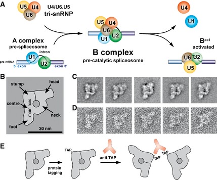
Figure 1. Architecture of the yeast spliceosomal B complex.
-
ASchematic depiction of events taking place during catalytic activation of the yeast spliceosome. The tri‐snRNP binds to the A complex containing the U1 and U2 snRNPs to form the B complex. Subsequently, the U1 and U4 snRNAs are released and the spliceosome is rearranged to form the activated spliceosome (Bact complex).
-
B–DTwo‐dimensional structure of the spliceosomal B complex from Saccharomyces cerevisiae. The domain architecture of the B complex is summarised in the main view on the left (B). Class averages are shown in the upper row (C) and negative‐stain EM raw images of yeast B complexes displaying the main view in the lower row (D). The B complex comprises a ˜30‐nm‐long main axis from the centre of which an upwardly bent neck domain protrudes that is connected to a head domain. A central area of high stain uptake and a furrow stretching upwards from it are also indicated. The scale bar in panel (B) represents 30 nm.
-
ESchematic depiction of anti‐TAP antibody‐induced B complex dimerisation that is used to locate a TAP‐tagged protein in the spliceosomal B complex. The B complexes are depicted in the main view, the antibodies are shown in orange with their characteristic Y shape, and the positions of the TAP tags are shown.
The molecular architecture and three‐dimensional (3D) organisation of the spliceosomal B complex remain poorly understood. Although there are a number of high‐resolution 3D structures of spliceosomal proteins or snRNP particles (reviewed by; Ritchie et al, 2009; Galej et al, 2014), there is no crystal structure of a fully assembled spliceosome. The dynamic nature of the spliceosome and the compositional and conformational heterogeneity of the purified complexes make structural analysis challenging. These challenges have made electron microscopy (EM) the method of choice for structural studies with spliceosomal complexes (Stark & Lührmann, 2006). Electron cryomicroscopy has yielded inter alia low‐resolution 3D structures of the human B complex (Boehringer et al, 2004) and the majority of its building blocks, the U1 snRNP (Stark et al, 2001), the U2 snRNP subcomplex SF3b (Golas et al, 2003) and the U4/U6·U5 tri‐snRNP (Sander et al, 2006). Most recently, 3D cryo‐EM structures of the U4/U6·U5 tri‐snRNP complex from S. cerevisiae and of an endogenous late‐assembly stage spliceosome from S. pombe have been published at a resolution of 5.9 and 3.6 angstrom, respectively (Nguyen et al, 2015; Yan et al, 2015). Despite this knowledge, it is not possible to describe unambiguously the molecular architecture of the B complex and to discern its organisation. To overcome this limitation, immuno‐labelling studies have been performed to locate proteins and RNA molecules within spliceosomal complexes (reviewed by Lührmann & Stark, 2009).
Following our previous work (Häcker et al, 2008), we adapted the method for locating proteins in the tri‐snRNP to the yeast spliceosomal B complex by making use of the tandem affinity‐purification (TAP) tag (Rigaut et al, 1999) and polyclonal anti‐TAP antibodies. We used antibody‐induced spliceosome dimerisation to locate proteins from each major building block and to understand the architecture of the B complex. We located three U5 snRNP proteins, and two U4/U6 di‐snRNP proteins and the tri‐snRNP protein Prp38. To reveal the U2 snRNP within the B complex, we located two SF3a and two SF3b proteins. In addition to the snRNP‐specific proteins, we located the RES complex protein Bud13. These locations represent the first extensive mapping of a fully assembled spliceosome and lead to a better understanding of its architecture. Even if the catalytic centre has not yet been formed in the B complex, understanding the organisation of snRNPs and non‐snRNP proteins in the pre‐catalytic spliceosome paves the way to understanding the rearrangement events necessary for catalytic activation.
Results
Purification and morphology of yeast spliceosomal B complexes
In order to obtain immuno‐labelled B complexes with the necessary degree of purity and in sufficient amount for EM analysis, we adapted the method previously established for stalling and purifying yeast spliceosomal B complexes (Fabrizio et al, 2009). We assembled B complexes in vitro on [32P]‐labelled M3‐ActinΔ6 pre‐mRNA in yeast extracts from strains expressing the TAP‐tagged proteins of interest. To purify the complexes we used the MS2‐MBP (maltose‐binding protein) affinity‐purification method (Zhou & Reed, 2003) with subsequent density‐gradient ultracentrifugation in the presence of glutaraldehyde (GraFix; Kastner et al, 2008). GraFix greatly enhances the quality of EM images of spliceosomal particles.
We found that the modified sequence of purification steps (i.e. with omission of the first glycerol‐gradient centrifugation) compared with the method previously described (Fabrizio et al, 2009) produced spliceosomal particles that were nearly identical in sedimentation value (Fig EV2A), protein and RNA composition (Fig EV2B) and overall structure. The purification yielded homogenous spliceosomal B complexes, with a very small number of fragmented particles and almost no aggregation (Fig EV2C). After image acquisition, class averages were generated which confirmed that the B complexes purified by the modified method exhibited the same (two‐dimensional) structure (Fig 1C) as the previously published B complexes (Fabrizio et al, 2009).
Figure EV2. Purification of yeast spliceosomal B complexes using the modified method.
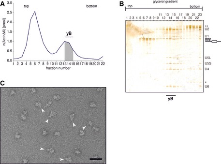
- Radioactivity profile of the glycerol gradient. The free pre‐mRNA migrated in fractions 4–7 and the yeast spliceosomal B complexes (yB) in fractions 13–15.
- RNA composition of the purified yeast spliceosomal complexes. In fractions 13–16 that correspond to the B complex peak (˜40S), all five snRNAs (U2, U1, U5L/U5S, U4 and U6) can be found, although the U1 snRNA seems to be present in substoichiometric amounts. The band corresponding to the M3‐ActinΔ6 pre‐mRNA is labelled with a schematic drawing. * labels the band of 5S ribosomal RNA, and ** marks the bands corresponding to the ribosomal 18S and 28S RNAs that are present as contaminations in the high‐density fractions.
- Negative‐stain EM overview image (taken at 80,000‐fold magnification) of the purified yeast B complexes. The purification yielded a homogenous sample without any aggregates, and a large number of particles display the features characteristic of the main view of the yeast B complex (indicated with white arrows). The scale bar represents 60 nm.
A schematic drawing of the domain architecture of the B complex is given in Fig 1B. One predominant characteristic orientation of the particles was observed in electron micrographs (Fig EV2C). This view we term “main view”; it is characterised by an almost straight, ~30‐nm‐long main axis (Fig 1B). The upper one‐third of the main axis forms the “stump” domain and the domain making up the bottom one‐third the “foot”. From the stump, the “head” protrudes; this displays some structural variability and can appear more globular or elongated and can project from the main axis at an angle close to 90°. Characteristic for this view is the neck structure, the roundish bridge that protrudes upwards from the central region of the main axis and connects to the head domain. Although the head frequently exhibits an elongated shape similar to that of the main axis, in most cases it is shorter and can thus be distinguished from the main axis. In addition, a line of stain separates it from the stump region, to which it connects in most of the images. Moreover, the outline of the main axis is straighter and better defined than that of the head. These characteristic domains can be easily identified, not only in class averages (Fig 1C) but also in the raw images (Fig 1D).
Anti‐TAP antibodies induce specific dimerisation of spliceosomes that contain a single TAP‐tagged protein
As described earlier (Häcker et al, 2008), proteins were located by immuno‐labelling of the tri‐snRNP particle, locating the antibody directly within EM images. However, owing to the high molecular mass of the B complex, this strategy was not applicable to locate proteins in spliceosomes, since the IgG molecule is too small to be visible when bound to the particle.
As schematically depicted in Fig 1E, upon addition of rabbit polyclonal anti‐TAP antibodies, the spliceosomes formed dimers (~70S) that could be separated from monomeric B complexes (~40S). The example of C‐terminally TAP‐tagged Brr2 (Fig 2A) shows that dimer formation can be considered specific, as no dimers were formed when anti‐TAP antibodies were added to untagged spliceosomes (Fig 2B). The specific formation of B complex dimers was also observed when the TAP tag was fused to various other spliceosomal proteins (Fig EV3). It can be ruled out that the introduction of the TAP tag to any of the spliceosomal proteins used in this work affects their function in splicing, since none of the yeast strains used showed any severe growth defect (Appendix Fig S1) and all prepared extracts were active in in vitro splicing albeit in some cases (Prp11‐TAP, Cus1‐TAP and Bud13‐TAP) with lower efficiency (Appendix Fig S2). To confirm that the increase in the sedimentation coefficient upon anti‐TAP addition is a result of dimer formation and not spliceosome aggregation, we took negative‐stain EM images using the gradient fractions corresponding to a sedimentation coefficient of 70S for EM specimen preparation. These images (Fig 3) only show dimeric particles and no sign of aggregates, no matter which protein carried the TAP tag. These particles show the typical B complex shape. In addition, mass‐spectrometric analysis of the 70S gradient fractions show that the spliceosome dimers have a protein composition that is typical of the yeast B complex (Appendix Table S1). The observed spliceosome dimerisation is specific to the presence of the TAP tag and the addition of anti‐TAP antibodies, and the spliceosomes labelled in this way can be used to locate the TAP‐tagged protein since the label (a complete spliceosome) can easily and reliably be identified in electron micrographs.
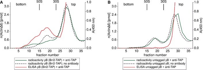
Figure 2. Antibody addition to B complexes harbouring TAP‐tagged Brr2 leads to specific spliceosome dimerisation.
-
A, BGradient profiles of affinity‐purified, [32P]‐labelled B complexes (yB) containing C‐terminally TAP‐tagged Brr2 (A) or tagless Brr2 (B). Spliceosomes were separated by glycerol‐gradient ultracentrifugation in the presence of glutaraldehyde. The colour code is explained in the legend below each graph. The fractions in which E. coli ribosomal subunits migrated using the same centrifugation conditions and salt concentrations are labelled 30S and 50S. A shift in the sedimentation coefficient from ˜40S to ˜70S can only be observed when both the TAP tag and anti‐TAP antibodies are present (green line in A), and only then do antibodies co‐migrate with spliceosomal complexes (red line in A). In the absence of the anti‐TAP antibody, spliceosome dimerisation was not observed (dotted graphs in A and B).
Figure EV3. Gradient profiles of anti‐TAP‐labelled spliceosomal B complexes harbouring selected TAP‐tagged proteins.
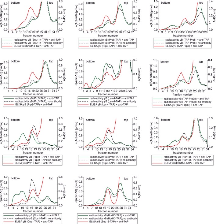
The green line represents the radioactivity profile of the gradient on which immuno‐labelled B complexes were separated. The dotted line is the radioactivity profile of the control gradient on which B complexes without antibody addition were separated. The signal of the ELISA that was performed to visualise the antibody content of the gradient fractions is shown in red. The protein fused to the TAP tag that was present in spliceosomal B complexes is identified in the legend below each graph. TAP‐(protein name) stands for an N‐terminal TAP tag and (protein name)‐TAP for a C‐terminal TAP tag.
Figure 3. Typical negative‐stain electron micrographs of yeast spliceosomal B complex dimers.
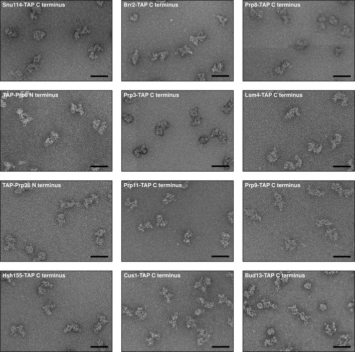
Negative‐stain EM images of B complex dimers were taken at 80,000‐fold magnification to give an overview over the sample. For each image, a scale bar representing 60 nm is shown and the protein carrying the TAP tag is named. The purification of immuno‐labelled spliceosomes yielded in all cases homogenous B complex dimers that did not show any sign of aggregation.
The B complex main axis harbours the U5 snRNP proteins Snu114, Brr2 and Prp8
To locate the U5 snRNP protein Snu114, we used B complexes containing Snu114 tagged C‐terminally. B complex dimers were analysed as described above, and negative‐stain EM images were recorded (Fig 4A). For analysis, we only considered dimers in which at least one particle displayed the B complex main view (“main‐view dimers”) since the main view was the only view where unambiguous domain assignment was possible. Seven main‐view dimers characteristic of the entire data set (100 main‐view dimers were used for each protein located in this study) are shown (Fig 4A). As it was observed in the majority of main‐view dimers, only one of the two particles of the dimer displayed the B complex main view; the other particle (from now on called “second particle”) very often had no recognisable features and therefore was used only as a label for the TAP tag. The dimers from the Snu114 labelling show a relatively high variation in the position of the second particle with respect to the main‐view particle. The connection between the two particles sometimes occurred through the neck‐proximal side of the foot domain (Fig 4A, frames 5–7), sometimes through the neck‐distal side of the foot domain (Fig 4A, frames 1, 2 and 4) and in some dimers through the middle of the main axis on the neck‐distal side (Fig 4A, frame 3). In many main‐view dimers, the two particles had an extensive contact area and the antibody bridging the two particles was not directly visible.
Figure 4. Locations of the U5 snRNP proteins Snu114, Brr2 and Prp8 in the yeast spliceosomal B complex.
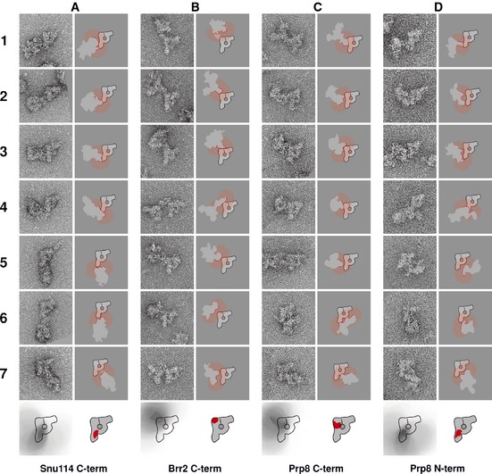
- C‐terminus of Snu114.
- C‐terminus of Brr2.
- C‐terminus of Prp8.
- N‐terminus of Prp8.
To determine the area within the main‐view particle in which the TAP tag and thus the C‐terminus of Snu114 are located, we applied distance restrictions based on the size of an IgG molecule. We assumed that the Fab and Fc domains of an IgG are both 7 nm long (Silverton et al, 1977). Dimerisation of two particles, each carrying one TAP tag, can occur by binding of one Fab domain to the calmodulin‐binding peptide (CBP) of the main‐view particle and the other Fab domain to the CBP of the second particle. Another possibility is that one Fab domain binds to the CBP of one particle and the Fc domain binds to one protein A domain of the second particle. On the assumption that an IgG displays some flexibility in its hinge region, the distance between the two TAP tags of a dimer cannot exceed 14 nm. If the dimerisation occurs through binding of two protein A domains from different particles to the Fc domain of the same IgG molecule, the distance between the two TAP tags involved is even smaller than 14 nm. The strategy we applied to determine the antibody‐binding site is exemplified for four dimers of C‐terminally‐tagged Snu114 in Fig 5. No matter which IgG domain binds to the TAP tags of the spliceosomes forming the dimer, the TAP tag of the main‐view particle cannot be more than 14 nm away from the outline of the second particle. The dimers of Fig 5A are shown schematically in Fig 5B, in which the outline of the second particle involved in dimer formation is shown in red. For each dimer, we then determined the area within the main‐view particle that is closer than 14 nm to the outline of the second particle (transparent red in Fig 5C). If that all four dimers are antibody‐induced, the TAP tag can only be located in that fraction of the 14 nm areas that is common to all four dimers (Fig 4D). Analysing all dimers of the data set and applying the criteria explained above, we were able to determine the area within the main‐view B complex where the C‐terminus of Snu114 is located, viz, the bottom half of the main axis but close to its centre without including the tip of the foot domain (Fig 5E and bottom drawing in Fig 4A).
Figure 5. Strategy used to deduce the location of the TAP tag within B complex dimers induced by anti‐TAP antibody.
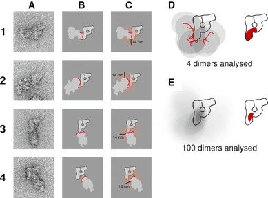
- Negative‐stained raw images of four main‐view dimers of Snu114‐TAP containing B complexes. These four dimers have been chosen as they represent all the different positions of the second particle with respect to the main‐view particle that can be found in the data set.
- Schematic depiction of the B complex dimers. The outline of the second particle at the dimerisation interface with the main‐view particle is drawn as a red line.
- Possible area of TAP tag location within the main‐view particle. The area within 14 nm of the second particle outline at the dimerisation interface is shown as a transparent red area. The TAP tag at the C‐terminus of Snu114 must be within this area in the main‐view particle.
- Deduced position of the TAP tag combining the knowledge gained from four dimers (A1–A4). The schematic diagrams of all four dimers have been aligned according to the main‐view particle and overlaid (left), and the area where all four possible TAP tag locations overlap can be identified as the darkest grey area within the B complex main‐view scheme. This area is highlighted in red on the right side.
- Final location of the C‐terminal TAP tag of Snu114 when 100 dimers are analysed. The area of maximum overlap deduced from overlaying all dimers of the data set (dark grey in the left‐hand sketch) is shown as a solid red area in the B complex sketch on the right.
The same strategy was used to locate the C‐terminus of Brr2. Fig 4B shows seven representative dimers. As can be seen here, the dimerisation interface is located on the head‐distal side of the stump region, in nearly all dimers. Very often, a considerable distance of the two particles within the dimer can be observed and the two spliceosomes are connected by a clearly visible, narrow bridge. However, the distance never exceeded 14 nm. These circumstances allow a relatively precise location. Applying the approach described above, we deduced that the C‐terminus of Brr2 is located in the top (head‐distal) corner of the main axis in the area depicted in the schematic drawing at the bottom of Fig 4B.
Our data indicate that the C‐termini of Snu114 and Brr2 are clearly separated within the main axis. As reviewed in the study by Grainger and Beggs (2005), Snu114 has been shown to interact with the N‐terminal part of Prp8, whereas Brr2 interacts with the C‐terminus of Prp8. We located both, the C and the N‐termini of the 280‐kDa protein Prp8 in the B complex. In the case of C‐terminally TAP‐tagged Prp8, the main‐view dimers can be divided into two groups. In the majority of dimers, the second particle contacts the main‐view B complex in the middle or at the top of the main axis on the neck‐distal side (Fig 4C, frames 1–5). The second group comprises dimers where the second particle contacts the main‐view spliceosome at the neck (Fig 4C, frames 6 and 7). In these relatively rare cases, the two particles are close to each other with a large contact area, indicating that the TAP tag may be located quite far from the particle periphery. Analysing all dimers collected, we concluded that the C‐terminus of Prp8 must be located in the upper half of the main axis, closer to the middle than to the C‐terminus of Brr2 (sketch in Fig 4C).
In dimers obtained with N‐terminally‐tagged Prp8, the dimerisation occurred either in the bottom two‐thirds of the main axis on the neck‐distal side (Fig 4D, frames 1–4) or in the neck domain (Fig 4D, frames 5–7). From this, we deduced that the N‐terminus of Prp8 must be located in the bottom two‐thirds of the main axis (sketch in Fig 4D) but not at the very bottom of the foot domain. This area is close to the one determined for the C‐terminus of Snu114.
From the locations of the proteins Snu114, Brr2 and Prp8, it can be concluded that the main axis of the yeast B complex comprises the U5 snRNP. In this, Brr2 is located at the top of the main axis and Prp8 in the middle of the axis, with its C‐terminus closer to the top and the N‐terminus closer to the foot, in an area where the C‐terminus of Snu114 also resides.
The U4/U6 snRNP proteins Prp3 and Lsm4 are located in the neck domain
To identify the domains of the B complex comprising the U4/U6 di‐snRNP, we located the C‐termini of Prp3 and Lsm4. This also helped us to locate indirectly the 3′ end of the U6 snRNA. The dimers obtained with TAP‐tagged Prp3 (Fig 6A) are all connected through the neck domain. This places the area in which the C‐terminus of Prp3 is located in the neck domain of the B complex. In some of the dimers, a distance between the two particles with a clearly visible bridge can be observed (Fig 6A, frames 2 and 3), so that a location in the main axis or the head can be ruled out. Our conclusion is that Prp3 is located in the upper end of the neck where it connects to the head (sketch at the bottom of Fig 6A).
Figure 6. Locations of the U4/U6·U5 tri‐snRNP proteins Prp3, Lsm4 and Prp38 in the spliceosomal B complex.
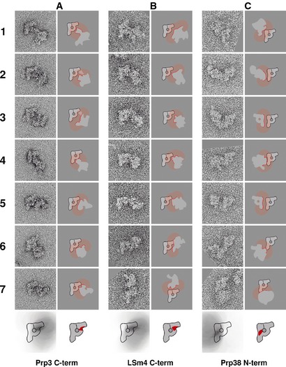
- C‐terminus of Prp3.
- C‐terminus of Lsm4.
- N‐terminus of Prp38.
For the C‐terminus of Lsm4, we obtained main‐view dimers connected at the neck domain (Fig 6B, frames 1–6) similar to those found for Prp3. In addition, we found dimers that were connected at the head domain in a region distal from the main axis (Fig 6B, bottom frame). Therefore, the area where the C‐terminus of Lsm4 is located covers the top of the neck and the bottom part of the head domain (sketch at the bottom of Fig 6B). From these data, we conclude that the 3′ end of the U6 snRNA is located in the region that joins the neck and head. Probably, from there the U4/U6 stem II extends.
The tri‐snRNP protein Prp38 is located in the middle of the main axis
Furthermore, we located the N‐terminus of Prp38, a U4/U6·U5 tri‐snRNP protein which is important for the release of the U4 snRNA from the spliceosome (Xie et al, 1998). As deduced from the B complex dimers harbouring TAP‐Prp38 (Fig 6C), this protein resides in the middle of the main axis, where it connects to the neck domain. We found the N‐terminus of Prp38 to be in close proximity to the C‐termini of Snu114 and Prp8 and the N‐terminus of Prp8. Therefore, we conclude that the middle of the main axis is the binding interface of the U5 and the U4/U6 snRNPs.
The B complex head domain harbours the U2 snRNP
Next, we identified the position of the U2 snRNP within the B complex. To determine the location of the heterotrimeric SF3a complex, we located the C‐termini of Prp11 and Prp9. In the majority of B complex dimers obtained with Prp11‐TAP, the second particle touches the main‐view particle at the neck domain (Fig 7A, frames 1–5). In some of these dimers, a clearly visible bridge between the particles can be observed (Fig 7A, frames 3 and 4). In others, the second particle is in contact with the main‐view particle at the top of the head domain (Fig 7A, frames 6 and 7). After considering all dimers and applying the method described (see above and Fig 5), we concluded that the C‐terminus of Prp11 is located in the head–neck interface (Fig 7A, bottom) region largely overlapping with the area where the C‐terminus of Lsm4 is located.
Figure 7. Locations of the C‐termini of the U2 snRNP proteins Prp11, Prp9, Hsh155 and Cus1 and the RES complex protein Bud13.
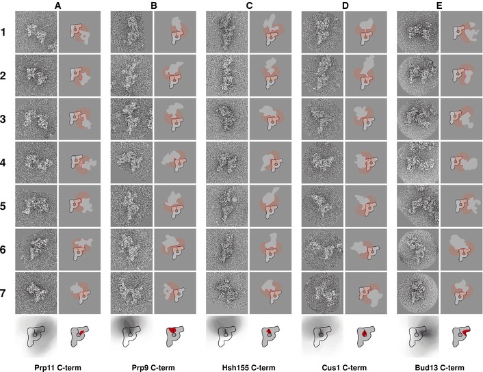
- C‐terminus of Prp11.
- C‐terminus of Prp9.
- C‐terminus of Hsh155.
- C‐terminus of Cus1.
- C‐terminus of Bud13.
In contrast to this, when Prp9 carried the TAP tag, no dimers were observed in which the connection of the two spliceosomes occurred at the neck in images of dimeric B complexes. In this case, all dimers were connected either at the top of the head domain (Fig 7B, frames 1–3) or at the top of the main axis (Fig 7B, frames 4–7). Thus, the C‐terminus of Prp9 is located in the top part of the B complex in the area where the head domain is connected to the stump domain (bottom drawing in Fig 7B).
We then located the C‐termini of Hsh155 and Cus1 as representatives of the SF3b complex. The dimers obtained with Hsh155‐TAP are very similar to those produced using Prp9‐TAP. In approximately half of the dimers, the two particles are connected at the top of the head domain (Fig 7C, frames 1, 2, 4 and 6), and in the other half of the dimers, the connection occurs at the top of the stump domain (Fig 7C, frames 3, 5 and 7). Therefore, we concluded that Hsh155 is located in the head–stump interface region (sketch at the bottom of Fig 7C).
A similar situation was found for the C‐terminus of Cus1. In most of the dimers, the dimerisation interface is the top of the head–stump joining region (Fig 7D, frames 1–3) or the top of the stump domain (Fig 7D, frames 4–6). However, in rare cases, the two particles of a dimer are connected at the neck domain (Fig 7D, frame 7). In addition, the particles are relatively close to each other in each dimer. Thus, the C‐terminus of Cus1 is also located in the head–stump interface region but closer to the centre of the particle, further away from the particle outline, as shown in the sketch at the bottom of Fig 7D.
In summary, the four U2 snRNP proteins were found in the head domain, in areas spanning from the head–stump interface region (Prp9, Hsh155 and Cus1) to the head–neck interface region (Prp11). We conclude that the head is the domain of the spliceosomal B complex that harbours the U2 snRNP, with the SF3b proteins being located closer to the main axis that contains the U5 snRNP. The locations of SF3a proteins suggest interfaces with both the U5 axis and the U4/U6 neck domain.
The RES complex protein Bud13 is located in the head of the B complex
In addition to the snRNP proteins, the spliceosomal B complex contains proteins that are organised in non‐snRNP subcomplexes. One such complex is the heterotrimeric RES complex formed by Bud13, Snu17 and Pml1 (Dziembowski et al, 2004). The RES complex is required for splicing since depletion of Snu17 has been shown to stall spliceosomes at a B‐like stage, before release of the U1 snRNP (Gottschalk et al, 2001). Furthermore, the RES complex has been shown to interact with SF3b proteins (Wang et al, 2005) and with the pre‐mRNA downstream of the branch point (Wysoczański et al, 2014). To be able to determine the position of the RES complex, we located the C‐terminus of its largest protein, Bud13. In most of the B complex dimers obtained with Bud13‐TAP, the second particle was connected at the neck domain (Fig 7E, frames 1–5). However, a few dimers where the connection occurred through the top of the head domain were observed (Fig 7E, frames 6 and 7). On the basis of all dimers analysed, we deduce that Bud13 is located in an area of the U2 snRNP‐containing head domain of the B complex close to the U4/U6 snRNP‐containing neck domain (sketch at the bottom of Fig 7E), overlapping to a large degree with the areas we determined for Lsm4 and Prp11, respectively.
Discussion
We located the C‐termini of ten and the N‐termini of two spliceosomal proteins that were selected to represent all building blocks of the yeast spliceosomal B complex present in stoichiometric amounts. For this purpose, we developed a method to specifically create spliceosome dimers upon antibody addition to spliceosomal B complexes that incorporated a TAP‐tagged version of the protein of interest. In addition to efficient dimer formation, the genetic tagging system that we applied also provided a positive control for the specificity of antibody binding and the final location by comparison with the untagged version. Moreover, as the same antibody was used in this study for all localisation experiments, the observation of different location sites for different proteins provided an intrinsic control of the specificity of the observed epitopes.
The C‐termini of the three U5 snRNP proteins Prp8, Brr2 and Snu114, and also the N‐terminus of Prp8, were all found on the elongated main axis of the B complex (see Fig 8A for a summary). In the middle of the main axis, in the region from which the neck domain protrudes, we found the N‐terminus of the U4/U6·U5 tri‐snRNP protein Prp38. The C‐termini of Prp3 and Lsm4, two U4/U6 snRNP proteins, were found at the upper end of the neck domain (Fig 8B), the domain that connects the main axis with the head. The head domain harboured the C‐termini of the U2 snRNP proteins Prp11, Prp9, Hsh155 and Cus1 as well as the C‐terminus of the RES complex protein Bud13 (Fig 8C). These locations provide, for the first time, important and novel insight into the snRNP architecture of the spliceosomal B complex.
Figure 8. Summary of the protein positions and snRNP architecture of the B complex from Saccharomyces cerevisiae .
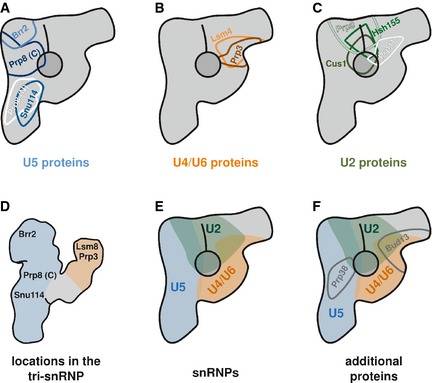
- Locations of the three U5 snRNP proteins Prp8 (C‐terminus in dark blue and N‐terminus in white), Brr2 (light blue) and Snu114 (middle blue).
- Locations of the two U4/U6 di‐snRNP proteins Lsm4 (orange) and Prp3 (brown).
- Locations of the SF3a proteins Prp11 (very light green), Prp9 (bright green) and the SF3b proteins Hsh155 (middle green) and Cus1 (dark green).
- Positions of the proteins that have been mapped in the yeast tri‐snRNP (Häcker et al, 2008).
- snRNP architecture of the yeast spliceosomal B complex. The U5 snRNP (blue) occupies the entire main axis, the neck domain is made up by the U4/U6 di‐snRNP (orange), and the head domain harbours the U2 snRNP (green).
- Locations of Prp38 and the RES complex protein Bud13.
The U5 snRNP occupies the entire main axis of the yeast B complex
The positions of the U5 snRNP proteins clearly show that the U5 snRNP is located on the main axis of the B complex. At the upper end of the stump region, we found the C‐terminus of Brr2, which consists of two helicase cassettes that make up the C‐terminal two‐thirds of the protein. The 3D structure of the two helicase domains of the S. cerevisiae Brr2 protein (amino acids 442–2,163) in complex with the C‐terminal Jab1/MPN domain of Prp8 has been solved by X‐ray crystallography (Nguyen et al, 2013). In the crystal structure, the N‐terminal helicase cassette is shown to be the only interaction site with the C‐terminal Jab1/MPN domain of Prp8, which in human has been shown to inhibit Brr2′s helicase activity (Mozaffari‐Jovin et al, 2013), thus preventing U4/U6 unwinding and consequently spliceosome activation. In general, Prp8 has been shown to be a key regulator of the DEAD‐box helicase Brr2 (Mozaffari‐Jovin et al, 2012; Nielsen & Staley, 2012). Indeed, these findings are consistent with our location of the C‐terminus of Prp8 in the bottom two‐thirds of the stump, close to Brr2. We found that the N‐terminus of Prp8 is located in an area spanning the middle of the main axis to the upper part of the foot region, overlapping only to a small degree with the area where the C‐terminus is located.
We found the C‐terminus of Snu114 (Fabrizio et al, 1997) in the lower half of the main axis, overlapping to a large extent with the area where the N‐terminus of Prp8 was found. This finding is consistent with the fact that Snu114 has been shown to interact with Prp8 (in the region of amino acids 437–770: Boon et al, 2006; Grainger & Beggs, 2005).
In addition to the U5 snRNP and U4/U6 di‐snRNP proteins, the tri‐snRNP contains a set of proteins that are stably associated only in the tri‐snRNP (Gottschalk et al, 1999; Stevens & Abelson, 1999) and that are incorporated into the B complex (Fabrizio et al, 2009). Prp38 is a member of this group of proteins. We located the N‐terminus of Prp38 in the middle of the main axis, where the neck domain originates, in an area that overlaps to a great extent with the positions of Snu114 and the N‐terminus of Prp8. This result is consistent with previous findings that Prp38 can be co‐purified with the U5 snRNP (Stevens et al, 2001).
The B complex harbours the tri‐snRNP in a structurally well‐preserved, open conformation
Within the neck domain of the B complex, we found the C‐termini of the U4/U6 di‐snRNP proteins Prp3 and Lsm4. Prp3, together with its interaction partner Prp4, binds to the U4/U6 snRNA duplex in the region of stem II (Nottrott et al, 2002). Lsm4 is part of the Lsm complex that binds to the 3′ end of the U6 snRNA (Achsel et al, 1999). The structure of the Lsm proteins in complex with a five‐nucleotide‐long RNA sequence from the 3′ region of the U6 snRNA has recently been solved (Zhou et al, 2014). We located Prp3 and Lsm4 at the top of the neck domain of the B complex. We therefore concluded that the neck domain harbours the U4/U6 di‐snRNP, with the 3′ end of the U6 snRNA positioned at the very top of the neck (Lsm4 location), where it connects to the head domain of the B complex. Prp3 was located directly at the bottom of this area; therefore, the U4/U6 stem II may also be located here.
The U4/U6·U5 tri‐snRNP has previously been mapped extensively by a similar method for locating proteins (Häcker et al, 2008). The yeast tri‐snRNP and the B complex show striking structural similarities (compare our Fig 1C with Fig 1C and D in the publication by Häcker et al, 2008). Just like the B complex, the tri‐snRNP displays a ~30‐nm‐long main body from which a second domain protrudes upwards (termed the “arm domain” in the tri‐snRNP). However, the tri‐snRNP does not have a domain homologous to the B complex's head domain. In the tri‐snRNP, the C‐termini of three U5 snRNP proteins (Prp8, Brr2 and Snu114) were found in the main body of the tri‐snRNP, with Brr2 occupying the very top region. In the tri‐snRNP, Prp8 is located directly below Brr2 with Snu114 following further towards the bottom. This exactly reflects the pattern we found in the B complex. Furthermore, in the tri‐snRNP, Prp3 is in the top half, and Lsm8 at the very top, of the arm domain. In the crystal structure (Zhou et al, 2014), Lsm4 and Lsm8 are in direct contact; thus, the distance of these proteins can be considered negligible compared with the resolution limits of EM‐based localisation methods. Our conclusion is therefore that the arm domain of the tri‐snRNP and the neck domain of the B complex have the same protein pattern. With this information, it is now possible to place the tri‐snRNP unambiguously into the structure of the B complex (main view). When doing so, the areas of all the proteins that have been located in both complexes overlap almost perfectly. A summary of the protein positions in the tri‐snRNP is shown in Fig 8D and the location of the tri‐snRNP in the B complex in Fig 8E.
Negative‐stain electron micrographs and electron cryo‐microscopic images of the tri‐snRNP show that the arm domain is quite flexible (Häcker et al, 2008 and Supplementary Video 2 therein). The tri‐snRNP can adopt an open and a closed conformation with respect to the relative orientation of the free end of the arm domain towards the main body. We did not observe that kind of flexibility for the homologous neck domain of the B complex. The aforementioned fitting of the tri‐snRNP structure into the B complex main view only results in near‐perfect overlapping of the protein positions when the open conformation of the tri‐snRNP is used. We therefore conclude that the tri‐snRNP is structurally well preserved upon stable integration into the B complex and that it is locked into the open conformation.
It can be concluded that the region where the U5 snRNP binds to the U4/U6 di‐snRNP is the middle of the main axis and the base of the neck domain in the B complex. It has been shown that, in yeast, Prp38 is essential for the release of the U4 snRNA from the spliceosome and mutation of Prp38 stalls splicing at the B complex stage (Xie et al, 1998). Consistently with these results, we found Prp38 in the middle of the main axis in an area where the neck domain originates. In addition, the position of Prp38 overlaps with that of the N‐terminus of Prp8, which is in good agreement with the finding that Prp8 is a key regulator of the activation step, in which the U4/U6 snRNA duplex is unwound (Mozaffari‐Jovin et al, 2012, 2013; Nielsen & Staley, 2012).
The A complex is in contact with two distant tri‐snRNP sites associated, respectively, with Brr2 and the Lsm ring
We located the C‐termini of four U2 snRNP proteins (Prp11, Prp9, Hsh155 and Cus1) in the head domain of the B complex. This shows clearly that the U2 snRNP is located in this domain. After locating the U4/U6·U5 tri‐snRNP, knowing the position of the U2 snRNP reveals the subunit architecture of the yeast spliceosomal B complex that is summarised in Fig 8E. As there is no domain homologous to the B complex head in the yeast tri‐snRNP (Häcker et al, 2008), we conclude that the head domain of the B complex is derived from the spliceosomal A complex. This conclusion is also consistent with the results from immuno‐localisation experiments in the human spliceosomal B complex that place the pre‐mRNA as well as the protein SF3b155 (the human homologue to Hsh155) in the head domain of the B complex (Wolf et al, 2009).
We found the C‐termini of the two SF3b proteins Hsh155 and Cus1 in the head domain at the interface with the main axis that is made up of the U5 snRNP. Probably the whole SF3b complex is located in this region of the head. We also located the C‐termini of the two SF3a complex proteins Prp11 and Prp9. Whereas the C‐terminus of Prp9 was located in the part of the head domain that is in contact with the upper end of the U5 snRNP, the C‐terminus of Prp11 is located in the part of the head that is in contact with the U4/U6 snRNP. The 3D structure of the yeast SF3a complex, containing more than half of the total SF3a mass, has been solved by X‐ray crystallography and displays an elongated structure with Prp9 at one end, Prp11 at the other end and Prp21 in between (Lin & Xu, 2012). This agrees with the distant locations of Prp11 and Prp9 found here.
From the positions of the U2 snRNP subcomplexes SF3a and SF3b, we could deduce the position of the A complex within the B complex. We found that the A complex has two main attachment sites to the tri‐snRNP in the yeast B complex: one at the upper part of the main axis in the region where we located the C‐termini of the U5 snRNP proteins Brr2 and Prp8 (overlapping in part with the areas of Prp9, Hsh155 and Cus1), and one at the upper end of the neck structure where the C‐termini of Lsm4 and Prp3 can be found (overlapping with the areas of Prp11 and Cus1). The finding that there is contact between the U2 snRNP and the U4/U6 snRNP in the B complex is consistent with previous results that show that stable tri‐snRNP integration into the spliceosome requires base‐pairing of the 5′ end of the U2 snRNA with the 3′ end of the U6 snRNA (Madhani & Guthrie, 1992). The existence of contact between the A complex and the U5 snRNP is supported by previous results from yeast two‐hybrid and co‐immunoprecipitation experiments, which showed a network of interactions involving SF3b proteins, Brr2, Prp8 and Snu114 (Hegele et al, 2012).
The RES complex can be found in the head domain of the B complex
We found the C‐terminus of the heterotrimeric RES complex protein Bud13 in the head–neck interface region (Fig 8F), in an area overlapping with the positions of Prp11 and Lsm4. Moreover, it overlaps to a small degree with the area where Hsh155 has been located. Our location of the C‐terminus of Bud13 points to the location of the RES complex core. The RES complex subunit Snu17 has been shown to bind to the U2 snRNP (Gottschalk et al, 2001), and results of a yeast two‐hybrid screen and co‐immunoprecipitation experiments prove that Snu17 interacts with SF3b complex proteins, Bud13 and the third RES complex protein Pml1 (Wang et al, 2005). The location of the RES complex in the head domain, overlapping with the area occupied by U2 snRNP proteins, is consistent with previous results. Furthermore, our findings agree with the finding that Snu17 can be cross‐linked to the pre‐mRNA between the branch point and the 3′ splice site (Wysoczański et al, 2014), where Hsh155 could also be cross‐linked (McPheeters & Muhlenkamp, 2003).
The organisation of the B complex indicates large rearrangements of the catalytic RNAs relative to the position of Prp8 during activation
The catalytic RNA network of the spliceosome is associated with Prp8, as this protein can be cross‐linked to the 5′ splice site, the 3′ splice site, the branch‐point region, one nucleotide of the U6 snRNA and the 5′ stem loop of the U5 snRNA (see reviews by Grainger & Beggs, 2005; and Wahl et al, 2009). However, the position of proteins in the B complex as mapped here indicates that in this precatalytic spliceosomal complex, there is a considerable distance between Prp8 and RNA sequences, such as U6 and the 5′ end of U2, that later form the catalytic centre. For example, whereas Prp8 is located in the elongated main axis of the B complex, the 3′ end of U6 could be indirectly mapped to the neck domain. Furthermore, the U2 snRNA was mapped indirectly by locating various SF3a and SF3b proteins to the head domain of the B complex. The pre‐mRNA also appears to be located in the head, based on immuno‐labelling results in the human B complex (Wolf et al, 2009), and on the fact that SF3a and SF3b proteins that bind to the pre‐mRNA at or in the vicinity of the branch‐point region (Staknis & Reed, 1994) are also located in the head domain of the yeast B complex. Thus, our results imply that during activation of the spliceosome, there is a large movement of the spliceosome's catalytic RNA elements relative to Prp8. Indeed, the B complex is known to be extensively remodelled during the activation step (Fabrizio et al, 2009). Our results thus provide initial insights into the molecular nature of the RNP remodelling events that occur during spliceosome activation. Applying the method for locating proteins that we developed in this study to later spliceosomal complexes (Bact, B* and C) should lead to a more detailed understanding of these RNP rearrangements.
During revision of the manuscript, the 3D structure of the S. cerevisiae tri‐snRNP, determined by cryo‐EM at a resolution of 5.9 Å, was reported (Nguyen et al, 2015). On the basis of our fitting of the tri‐snRNP into the B complex, our protein locations are consistent with the protein positions in the 3D structure.
Materials and Methods
Strains and plasmids
The yeast strains used in this work expressing the respective C‐terminally TAP‐tagged proteins were constructed in previous work (Häcker et al, 2008) or produced according to the method described previously (Puig et al, 2001). By using the plasmid pBS1479 (Puig et al, 2001) as a template, the C‐terminal TAP cassette was amplified and fused to the C‐terminus of the respective protein by PCR. Yeast strains expressing N‐terminally TAP‐tagged proteins were constructed in the same way, with the plasmid pBS1761 (Puig et al, 2001) as template. In some cases, the TEV protease cleavage site of the TAP tag was replaced by a PreScission protease cleavage site. In those cases, the plasmid pBS1539‐Psc (Kramer et al, 2014) was used as PCR template.
Purification and immunolabelling of spliceosomal B complexes
The method for stalling spliceosome assembly at the B complex stage and purifying the spliceosomal particles was an adaptation of the method described previously (Fabrizio et al, 2009). Uniformly [32P]‐labelled M3‐ActinΔ6 pre‐mRNA bearing three phage R17 MS2 binding sites at the 5′ end was produced by in vitro transcription with T7 RNA polymerase and pre‐incubated with a 15‐fold molar excess of the MS2‐MBP fusion protein (Das et al, 2000) in 20 mM HEPES (pH 7.9) at 4°C for 30 min. The MS2‐MBP‐bound pre‐mRNA was then incubated for 60 min with yeast whole‐cell extract (Gottschalk et al, 1999) under splicing conditions (60 mM K2HPO4/KH2PO4 pH 7.4; 3% w/v PEG 8000; 50 μM ATP; 2 mM spermidine; 2.5 mM MgCl2; 40% v/v yeast extract; 2 nM M3‐ActinΔ6 at 30–50 cpm/fmol). The typical scale of the splicing reaction was 100 ml. After complex assembly, the potassium concentration was adjusted to 150 mM and the precipitate was removed by centrifugation at 13,300 g and 4°C for 10 min. The supernatant was loaded on 2 ml amylose–agarose (New England Biolabs) that was pre‐equilibrated in G150 buffer (20 mM HEPES‐KOH pH 7.9; 1.5 mM MgCl2; 150 mM KCl; 0.5 mM DTT; 0.5 mM PMSF) containing 5% w/v glycerol and 0.01% w/v NP‐40. After washing with 10 ml of the same buffer and 50 ml of G75 buffer (20 mM HEPES‐KOH pH 7.9; 1.5 mM MgCl2; 75 mM KCl; 0.5 mM DTT; 0.5 mM PMSF) containing 5% w/v glycerol and 0.01% w/v, NP‐40 spliceosomes were eluted with 12 mM maltose in G75 buffer containing 5% w/v glycerol and 0.01% w/v NP‐40. From the peak fractions, ~10 pmol of B complexes was taken and incubated with 30 pmol of rabbit polyclonal anti‐TAP antibodies (Thermo Scientific) for 90 min on ice (for the control no antibodies were added). After antibody binding, the whole volume was loaded on a 10–30% w/v glycerol gradient with a parallel 0–0.4% w/v glutaraldehyde (Electron Microscopy Sciences) gradient in G75 buffer and centrifuged in a Sorvall TH660 rotor for 16 h at 4°C at 51,000 g (max.). The gradients were fractionated from the bottom in 125 μl fractions. The peak fractions were used directly for EM specimen preparation.
To confirm the presence of the antibody in the gradient fractions, an enzyme‐linked immunosorbent assay was carried out essentially as described by Wolf et al (2009).
Electron microscopy and image processing
Negative‐stain EM grids were prepared according to the single carbon film method (adapted from Kastner, 1998; and Kastner et al, 2008). Briefly, 50 mM glycine was added to the glycerol‐containing gradient fractions to quench the glutaraldehyde. Then, ~25 μl of the fraction was pipetted into a well in a black polyoxymethylene block pre‐cooled on ice. Next, a thin (< 10 nm) carbon film was floated on the sample and covered with a perforated carbon copper mesh grid, and particle adsorption was allowed to take place on ice until the desired particle density was achieved (typically 120–180 min). The excess of sample solution was blotted away, and the adsorbed particles were stained for 2 min with ~3.5% w/v uranyl formate (in ddH2O) on ice. After blotting the excess of staining solution, the grids were dried at room temperature for ~10 min and stored until image acquisition.
EM images were taken at room temperature in a CM200 FEG microscope (FEI) with 160 kV acceleration voltage at a magnification of 115,000 in eucentric height and a defocus of ~1.2 μm using a 4k × 4k CCD camera (TVIPS) with two‐fold binning of the pixels. For locating proteins, these raw images could be used directly. For making class averages, images taken at 80,000‐fold magnification were used. About 9,000 single‐particle images of monomeric yeast B complexes were collected in a semi‐automated way using the custom‐made automated picking software JohnHenry (B. Busch and H. Stark, unpublished data). The software suite CowEyes (H. Stark, manuscript in preparation) custom‐made by the 3D Electron Cryo‐Microscopy Research Group (Max Planck Institute for Biophysical Chemistry, Göttingen, Germany) was used for all subsequent image‐processing steps. The images were coarsened to a pixel size of 5 Å, and bandpass filtering was applied. After reference‐free alignment (Dube et al, 1993), the particles were classified by using multivariate statistical analysis (Van Heel & Frank, 1981; Van Heel, 1984) and averaged. The resulting averaged images of selected classes were used as references for the next round of alignment until the class averages were stable.
Strategy for locating proteins
The strategy used to locate spliceosomal proteins in negative‐stain EM images is described in detail in the Results section. Briefly, all main‐view dimers that could be identified were used for analysis. The outline of the second (non‐main‐view) particle that is involved in dimerisation was traced and the area within the main‐view particle within 14 nm of this outline was determined for each dimer. This area represents the sum of all possible positions of the TAP tag. Thereafter, all dimers were aligned according to the main‐view particle and the areas of potential TAP tag location where overlaid. The segment where all areas overlapped was then determined; this represents the final location of the TAP tag.
Author contributions
NR, BK, PF and RL designed the experiments. PF, BK and RL supervised the project. NR and CS performed the biochemical experiments and EM. NR, CS and BK analysed the data, and NR, BK, PF and RL wrote the paper.
Conflict of interest
The authors declare that they have no conflict of interest.
Supporting information
Appendix
Expanded View Figures PDF
Review Process File
Acknowledgements
The authors thank T. Conrad for large‐scale yeast fermentation in a bioreactor, E. Penka and W. Behrens‐Kranz for technical assistance, I. Häcker, K–L. Boon, C. Schneider and O. Dybkov for creating the yeast strains and H. Stark for providing EM infrastructure. This work was funded by a grant from the Deutsche Forschungsgemeinschaft (SFB860).
The EMBO Journal (2015) 34: 3059–3073
References
- Achsel T, Brahms H, Kastner B, Bachi A, Wilm M, Lührmann R (1999) A doughnut‐shaped heteromer of human Sm‐like proteins binds to the 3′‐end of U6 snRNA, thereby facilitating U4/U6 duplex formation in vitro . EMBO J 18: 5789–5802 [DOI] [PMC free article] [PubMed] [Google Scholar]
- Boehringer D, Makarov EM, Sander B, Makarova OV, Kastner B, Lührmann R, Stark H (2004) Three‐dimensional structure of a pre‐catalytic human spliceosomal complex B. Nat Struct Mol Biol 11: 463–468 [DOI] [PubMed] [Google Scholar]
- Boon K‐L, Norman CM, Grainger RJ, Newman AJ, Beggs JD (2006) Prp8p dissection reveals domain structure and protein interaction sites. RNA 12: 198–205 [DOI] [PMC free article] [PubMed] [Google Scholar]
- Das R, Zhou Z, Reed R (2000) Functional association of U2 snRNP with the ATP‐independent spliceosomal complex E. Mol Cell 5: 779–787 [DOI] [PubMed] [Google Scholar]
- Dube P, Tavares P, Lurz R, van Heel M (1993) The portal protein of bacteriophage SPP1: a DNA pump with 13‐fold symmetry. EMBO J 12: 1303–1309 [DOI] [PMC free article] [PubMed] [Google Scholar]
- Dziembowski A, Ventura A‐P, Rutz B, Caspary F, Faux C, Halgand F, Laprévote O, Séraphin B (2004) Proteomic analysis identifies a new complex required for nuclear pre‐mRNA retention and splicing. EMBO J 23: 4847–4856 [DOI] [PMC free article] [PubMed] [Google Scholar]
- Fabrizio P, Laggerbauer B, Lauber J, Lane WS, Lührmann R (1997) An evolutionarily conserved U5 snRNP‐specific protein is a GTP‐binding factor closely related to the ribosomal translocase EF‐2. EMBO J 16: 4092–4106 [DOI] [PMC free article] [PubMed] [Google Scholar]
- Fabrizio P, Dannenberg J, Dube P, Kastner B, Stark H, Urlaub H, Lührmann R (2009) The evolutionarily conserved core design of the catalytic activation step of the yeast spliceosome. Mol Cell 36: 593–608 [DOI] [PubMed] [Google Scholar]
- Galej WP, Nguyen THD, Newman AJ, Nagai K (2014) Structural studies of the spliceosome: zooming into the heart of the machine. Curr Opin Struct Biol 25: 57–66 [DOI] [PMC free article] [PubMed] [Google Scholar]
- Golas MM, Sander B, Will CL, Lührmann R, Stark H (2003) Molecular architecture of the multiprotein splicing factor SF3b. Science 300: 980–984 [DOI] [PubMed] [Google Scholar]
- Gottschalk A, Neubauer G, Banroques J, Mann M, Lührmann R, Fabrizio P (1999) Identification by mass spectrometry and functional analysis of novel proteins of the yeast [U4/U6.U5] tri‐snRNP. EMBO J 18: 4535–4548 [DOI] [PMC free article] [PubMed] [Google Scholar]
- Gottschalk A, Bartels C, Neubauer G, Lührmann R, Fabrizio P (2001) A novel yeast U2 snRNP protein, Snu17p, is required for the first catalytic step of splicing and for progression of spliceosome assembly. Mol Cell Biol 21: 3037–3046 [DOI] [PMC free article] [PubMed] [Google Scholar]
- Grainger RJ, Beggs JD (2005) Prp8 protein: at the heart of the spliceosome. RNA 11: 533–557 [DOI] [PMC free article] [PubMed] [Google Scholar]
- Häcker I, Sander B, Golas MM, Wolf E, Karagöz E, Kastner B, Stark H, Fabrizio P, Lührmann R (2008) Localization of Prp8, Brr2, Snu114 and U4/U6 proteins in the yeast tri‐snRNP by electron microscopy. Nat Struct Mol Biol 15: 1206–1212 [DOI] [PubMed] [Google Scholar]
- Hahn D, Kudla G, Tollervey D, Beggs JD (2012) Brr2p‐mediated conformational rearrangements in the spliceosome during activation and substrate repositioning. Genes Dev 26: 2408–2421 [DOI] [PMC free article] [PubMed] [Google Scholar]
- Van Heel M, Frank J (1981) Use of multivariate statistics in analysing the images of biological macromolecules. Ultramicroscopy 6: 187–194 [DOI] [PubMed] [Google Scholar]
- Van Heel M (1984) Multivariate statistical classification of noisy images (randomly oriented biological macromolecules). Ultramicroscopy 13: 165–183 [DOI] [PubMed] [Google Scholar]
- Hegele A, Kamburov A, Grossmann A, Sourlis C, Wowro S, Weimann M, Will CL, Pena V, Lührmann R, Stelzl U (2012) Dynamic protein‐protein interaction wiring of the human spliceosome. Mol Cell 45: 567–580 [DOI] [PubMed] [Google Scholar]
- Kandels‐Lewis S, Séraphin B (1993) Involvement of U6 snRNA in 5′ splice site selection. Science 262: 2035–2039 [DOI] [PubMed] [Google Scholar]
- Kastner B (1998) Purification and electron microscopy of spliceosomal snRNPs In RNP Particles, Splicing and Autoimmune Diseases, Schenkel DJ. (ed.), pp 95–140. Berlin Heidelberg: Springer; [Google Scholar]
- Kastner B, Fischer N, Golas MM, Sander B, Dube P, Boehringer D, Hartmuth K, Deckert J, Hauer F, Wolf E, Uchtenhagen H, Urlaub H, Herzog F, Peters JM, Poerschke D, Lührmann R, Stark H (2008) GraFix: sample preparation for single‐particle electron cryomicroscopy. Nat Methods 5: 53–55 [DOI] [PubMed] [Google Scholar]
- Kramer K, Sachsenberg T, Beckmann BM, Qamar S, Boon K‐L, Hentze MW, Kohlbacher O, Urlaub H (2014) Photo‐cross‐linking and high‐resolution mass spectrometry for assignment of RNA‐binding sites in RNA‐binding proteins. Nat Methods 11: 1064–1070 [DOI] [PMC free article] [PubMed] [Google Scholar]
- Laggerbauer B, Achsel T, Lührmann R (1998) The human U5‐200kD DEXH‐box protein unwinds U4/U6 RNA duplices in vitro . Proc Natl Acad Sci USA 95: 4188–4192 [DOI] [PMC free article] [PubMed] [Google Scholar]
- Lesser CF, Guthrie C (1993) Mutations in U6 snRNA that alter splice site specificity: implications for the active site. Science 262: 1982–1988 [DOI] [PubMed] [Google Scholar]
- Lin P‐C, Xu R‐M (2012) Structure and assembly of the SF3a splicing factor complex of U2 snRNP. EMBO J 31: 1579–1590 [DOI] [PMC free article] [PubMed] [Google Scholar]
- Liu S, Li P, Dybkov O, Nottrott S, Hartmuth K, Lührmann R, Carlomagno T, Wahl MC (2007) Binding of the human Prp31 Nop domain to a composite RNA‐protein platform in U4 snRNP. Science 316: 115–120 [DOI] [PubMed] [Google Scholar]
- Lührmann R, Stark H (2009) Structural mapping of spliceosomes by electron microscopy. Curr Opin Struct Biol 19: 96–102 [DOI] [PubMed] [Google Scholar]
- Madhani HD, Guthrie C (1992) A novel base‐pairing interaction between U2 and U6 snRNAs suggests a mechanism for the catalytic activation of the spliceosome. Cell 71: 803–817 [DOI] [PubMed] [Google Scholar]
- McPheeters DS, Muhlenkamp P (2003) Spatial organization of protein‐RNA interactions in the branch site‐3′ splice site region during pre‐mRNA splicing in yeast. Mol Cell Biol 23: 4174–4186 [DOI] [PMC free article] [PubMed] [Google Scholar]
- Mougin A, Gottschalk A, Fabrizio P, Lührmann R, Branlant C (2002) Direct probing of RNA structure and RNA‐protein interactions in purified HeLa cell's and yeast spliceosomal U4/U6.U5 tri‐snRNP particles. J Mol Biol 317: 631–649 [DOI] [PubMed] [Google Scholar]
- Mozaffari‐Jovin S, Santos KF, Hsiao H‐H, Will CL, Urlaub H, Wahl MC, Lührmann R (2012) The Prp8 RNase H‐like domain inhibits Brr2‐mediated U4/U6 snRNA unwinding by blocking Brr2 loading onto the U4 snRNA. Genes Dev 26: 2422–2434 [DOI] [PMC free article] [PubMed] [Google Scholar]
- Mozaffari‐Jovin S, Wandersleben T, Santos KF, Will CL, Lührmann R, Wahl MC (2013) Inhibition of RNA helicase Brr2 by the C‐terminal tail of the spliceosomal protein Prp8. Science 341: 80–84 [DOI] [PubMed] [Google Scholar]
- Nguyen THD, Li J, Galej WP, Oshikane H, Newman AJ, Nagai K (2013) Structural basis of Brr2‐Prp8 interactions and implications for U5 snRNP biogenesis and the spliceosome active site. Structure 21: 910–919 [DOI] [PMC free article] [PubMed] [Google Scholar]
- Nguyen THD, Galej WP, Bai X, Savva CG, Newman AJ, Scheres SHW, Nagai K (2015) The architecture of the spliceosomal U4/U6.U5 tri‐snRNP. Nature 523: 47–52 [DOI] [PMC free article] [PubMed] [Google Scholar]
- Nielsen KH, Staley JP (2012) Spliceosome activation: U4 is the path, stem I is the goal, and Prp8 is the keeper. Let's cheer for the ATPase Brr2!. Genes Dev 26: 2461–2467 [DOI] [PMC free article] [PubMed] [Google Scholar]
- Nottrott S, Urlaub H, Lührmann R (2002) Hierarchical, clustered protein interactions with U4/U6 snRNA: a biochemical role for U4/U6 proteins. EMBO J 21: 5527–5538 [DOI] [PMC free article] [PubMed] [Google Scholar]
- Puig O, Caspary F, Rigaut G, Rutz B, Bouveret E, Bragado‐Nilsson E, Wilm M, Séraphin B (2001) The tandem affinity purification (TAP) method: a general procedure of protein complex purification. Methods 24: 218–229 [DOI] [PubMed] [Google Scholar]
- Raghunathan PL, Guthrie C (1998) RNA unwinding in U4/U6 snRNPs requires ATP hydrolysis and the DEIH‐box splicing factor Brr2. Curr Biol 8: 847–855 [DOI] [PubMed] [Google Scholar]
- Rigaut G, Shevchenko A, Rutz B, Wilm M, Mann M, Séraphin B (1999) A generic protein purification method for protein complex characterization and proteome exploration. Nat Biotechnol 17: 1030–1032 [DOI] [PubMed] [Google Scholar]
- Ritchie DB, Schellenberg MJ, MacMillan AM (2009) Spliceosome structure: piece by piece. Biochim Biophys Acta 1789: 624–633 [DOI] [PubMed] [Google Scholar]
- Sander B, Golas MM, Makarov EM, Brahms H, Kastner B, Lührmann R, Stark H (2006) Organization of core spliceosomal components U5 snRNA loop I and U4/U6 Di‐snRNP within U4/U6.U5 Tri‐snRNP as revealed by electron cryomicroscopy. Mol Cell 24: 267–278 [DOI] [PubMed] [Google Scholar]
- Schultz A, Nottrott S, Hartmuth K, Lührmann R (2006) RNA structural requirements for the association of the spliceosomal hPrp31 protein with the U4 and U4atac small nuclear ribonucleoproteins. J Biol Chem 281: 28278–28286 [DOI] [PubMed] [Google Scholar]
- Silverton EW, Navia MA, Davies DR (1977) Three‐dimensional structure of an intact human immunoglobulin. Proc Natl Acad Sci USA 74: 5140–5144 [DOI] [PMC free article] [PubMed] [Google Scholar]
- Small EC, Leggett SR, Winans AA, Staley JP (2006) The EF‐G‐like GTPase Snu114p regulates spliceosome dynamics mediated by Brr2p, a DExD/H box ATPase. Mol Cell 23: 389–399 [DOI] [PMC free article] [PubMed] [Google Scholar]
- Staknis D, Reed R (1994) Direct interactions between pre‐mRNA and six U2 small nuclear ribonucleoproteins during spliceosome assembly. Mol Cell Biol 14: 2994–3005 [DOI] [PMC free article] [PubMed] [Google Scholar]
- Staley JP, Guthrie C (1999) An RNA switch at the 5′ splice site requires ATP and the DEAD box protein Prp28p. Mol Cell 3: 55–64 [DOI] [PubMed] [Google Scholar]
- Stark H, Dube P, Lührmann R, Kastner B (2001) Arrangement of RNA and proteins in the spliceosomal U1 small nuclear ribonucleoprotein particle. Nature 409: 539–542 [DOI] [PubMed] [Google Scholar]
- Stark H, Lührmann R (2006) Cryo‐electron microscopy of spliceosomal components. Annu Rev Biophys Biomol Struct 35: 435–457 [DOI] [PubMed] [Google Scholar]
- Stevens SW, Abelson J (1999) Purification of the yeast U4/U6.U5 small nuclear ribonucleoprotein particle and identification of its proteins. Proc Natl Acad Sci USA 96: 7226–7231 [DOI] [PMC free article] [PubMed] [Google Scholar]
- Stevens SW, Barta I, Ge HY, Moore RE, Young MK, Lee TD, Abelson J (2001) Biochemical and genetic analyses of the U5, U6, and U4/U6 x U5 small nuclear ribonucleoproteins from Saccharomyces cerevisiae . RNA 7: 1543–1553 [PMC free article] [PubMed] [Google Scholar]
- Wahl MC, Will CL, Lührmann R (2009) The spliceosome: design principles of a dynamic RNP machine. Cell 136: 701–718 [DOI] [PubMed] [Google Scholar]
- Wang Q, He J, Lynn B, Rymond BC (2005) Interactions of the yeast SF3b splicing factor. Mol Cell Biol 25: 10745–10754 [DOI] [PMC free article] [PubMed] [Google Scholar]
- Will CL, Lührmann R (2011) Spliceosome structure and function. Cold Spring Harb Perspect Biol 3: a003707 [DOI] [PMC free article] [PubMed] [Google Scholar]
- Wolf E, Kastner B, Deckert J, Merz C, Stark H, Lührmann R (2009) Exon, intron and splice site locations in the spliceosomal B complex. EMBO J 28: 2283–2292 [DOI] [PMC free article] [PubMed] [Google Scholar]
- Wysoczański P, Schneider C, Xiang S, Munari F, Trowitzsch S, Wahl MC, Lührmann R, Becker S, Zweckstetter M (2014) Cooperative structure of the heterotrimeric pre‐mRNA retention and splicing complex. Nat Struct Mol Biol 21: 911–918 [DOI] [PubMed] [Google Scholar]
- Xie J, Beickman K, Otte E, Rymond BC (1998) Progression through the spliceosome cycle requires Prp38p function for U4/U6 snRNA dissociation. EMBO J 17: 2938–2946 [DOI] [PMC free article] [PubMed] [Google Scholar]
- Xu Y, Petersen‐Bjørn S, Friesen JD (1990) The PRP4 (RNA4) protein of Saccharomyces cerevisiae is associated with the 5′ portion of the U4 small nuclear RNA. Mol Cell Biol 10: 1217–1225 [DOI] [PMC free article] [PubMed] [Google Scholar]
- Yan C, Hang J, Wan R, Huang M, Wong CCL, Shi Y (2015) Structure of a yeast spliceosome at 3.6‐angstrom resolution. Science 349: 1182–1191 [DOI] [PubMed] [Google Scholar]
- Zhou Z, Reed R (2003) Purification of functional RNA‐protein complexes using MS2‐MBP. Curr Protoc Mol Biol Chapter 27: Unit 27.3 [DOI] [PubMed] [Google Scholar]
- Zhou L, Hang J, Zhou Y, Wan R, Lu G, Yin P, Yan C, Shi Y (2014) Crystal structures of the Lsm complex bound to the 3′ end sequence of U6 small nuclear RNA. Nature 506: 116–120 [DOI] [PubMed] [Google Scholar]
Associated Data
This section collects any data citations, data availability statements, or supplementary materials included in this article.
Supplementary Materials
Appendix
Expanded View Figures PDF
Review Process File