Abstract
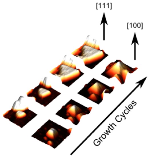
High resolution atomic force microscopy (AFM) is used to resolve the evolution of crystallites of a metal organic framework (HKUST-1) grown on Au(111) using a liquid-phase layer-by-layer methodology. The nucleation and faceting of individual crystallites is followed by repeatedly imaging the same submicron region after each cycle of growth and we find that the growing surface is terminated by {111} facets leading to the formation of pyramidal nanostructures for [100] oriented crystallites, and triangular [111] islands with typical lateral dimensions of tens of nanometres. AFM images reveal that crystallites can grow by 5–10 layers in each cycle. The growth rate depends on crystallographic orientation and the morphology of the gold substrate, and we demonstrate that under these conditions the growth is nanocrystalline with a morphology determined by the minimum energy surface.
Introduction
Metal–organic frameworks (MOFs) are polymeric crystalline materials comprising of metal ions bridged via co-ordination bonds by polydentate organic linkers.1 MOFs are typically formed by solvothermal reaction of the metal salts with the ligand, and have attracted great interest due to their potentially high internal surface area and porosity, which have great technological potential for gas storage and capture, sensing and catalysis.2 A wide range of organic molecules have been used as linkers for the construction of MOF materials, offering the potential for structures with highly tailored properties and topologies through the systematic control of the geometry and porosity3−5 as well as the integration of chemical functionality into the structure of the organic linker.6
It is also possible to grow MOF materials on substrates to form surface-mounted MOFs, so-called SURMOFS. SURMOFs have been grown with thicknesses varying from a few monolayers up to several microns and are of particular interest since they provide a route to the integration of porous functional materials with thin film devices.5,7,8 For example, SURMOF materials are promising candidates for fabricating highly responsive gas sensors since they strongly, and in some cases selectively, adsorb various gases.2 There have also been recent advances in the fabrication of SURMOF prototype semiconductor devices, and optical sensors based on interferometry.9−13
Several different approaches to the growth of SURMOF thin films have been reported.2 In the simplest method, a substrate is introduced into the solvothermal reaction solution leading, under suitable conditions, to the growth of a thin film of crystallites.14 It was further demonstrated that the termination of noble metal and oxide surfaces with, respectively, functionalized thiol and silane self-assembled monolayers (SAMs) can promote the growth of SURMOF films.15,16 In addition the crystallographic orientation of the film may be controlled through the use of SAMs with a specific end-group such as a −COOH or −OH termination.17 Functionalization of substrates with SAMs may be combined with lithographic techniques to pattern the substrate surface, for example using microcontact printing (μCP), to locally inhibit or promote SURMOF growth.15,18−20
While representing significant progress, this approach of direct solvothermal growth onto a substrate often results in rough, polycrystalline films or, alternatively, an inhomogeneous coverage of isolated crystals.19,21,22 The “layer-by-layer” (LBL) technique23 represents an alternative approach to the growth of SURMOFs and has been investigated as a possible route to improving the morphology of growth, and also the formation of SURMOF heterostructures. In the LBL method a substrate undergoes cyclic sequences of immersion in a solution of the metal ion, followed by immersion into a solution of the organic ligand (or vice versa) with potential rinsing steps between immersion.24 Variations on this implementation include exposure to metal/ligand solutions in flow reactors,25 and through spray deposition.20,26 Importantly, the substrate is only exposed to one component (metal or ligand) of the framework at each step in contrast to the solvothermal method which exposes the surface to both simultaneously. It has been proposed that only one monolayer forms in each cycle of immersion in framework component solutions and the SURMOF is thus grown in a controllable “layer-by-layer” manner.27 The LBL method can be combined with lithographic techniques and surface chemical functionalization using SAMs to enhance further the degree of control of the lateral, vertical and crystallographic geometry of MOF material.28 Extensions to this idea include the growth of MOF on MOF structures by changing the metal or ligand used during the growth process to create a layered material,29−31 and post-synthetic modification of linkers to change the chemical functionality of the linker molecules while preserving the MOF crystalline structure.32,33
The LBL method has been widely described as an epitaxial mode of growth and many of the more exotic approaches to SURMOF growth such as 3-component pillared structure MOFs31,34 or heteroepitaxial structures29,30,35 implicitly assume that the growth interface is, at least approximately, parallel to the substrate, analogous to the Frank–Van der Merwe mode of thin film growth, and advances by a monolayer in each growth cycle. Quartz crystal microbalance (QCM) measurements of the mass uptake during each step offer some support for this idealized model of growth,25,35,36 while images acquired using atomic force microscopy (AFM) have confirmed that the SURMOF thickness increases with the number of cycles, as expected.20,26,28,34,37 However, the growth rate in some cases vastly exceeds that predicted by the ideal LBL model,16,26,36,38−40 and there is no direct evidence for the addition of precisely one monolayer in each growth cycle. Indeed a recent scanning tunnelling microscopy (STM) study has shown no clear evidence for epitaxial features during the growth of the first few monolayers of MOF growth.41
Overall the growth of SURMOFs using the LBL method appears to be more complicated than that suggested by the idealized model. This has motivated the current study of the very early stages of the growth of SURMOFs by sequential dipping. In particular, we focus on the nucleation and subsequent growth which occurs in the first 10 growth cycles and use amplitude-modulated tapping (AC) mode AFM to acquire images of the surface after each of the first five cycles of growth, and then again after the tenth cycle. We use a variety of oriented and polycrystalline Au surfaces terminated, in some cases, by thiol layers. For most samples it is possible to return to exactly the same position on the surface allowing the repeated imaging of individual nanocrystals and subsequent characterization of their dimensions and orientation relative to the substrate at each stage of the growth process. The use of oriented gold surfaces complicates a direct comparison with other work although it is clear that our results agree with some aspects of previous work, notably the influence of thiol layers. However, under the growth conditions used here we do not observe the sequential addition of single MOF layers, and we find that the growing surface which is, in general, not parallel to the substrate.
HKUST-11 was chosen for this study since it has been studied extensively both as a bulk material and as a SURMOF thin film17 grown on thiol or silane functionalized surfaces.17,24,26 In addition due to the relative lability of Cu(II) centers, HKUST-1 can be deposited under ambient conditions at room temperature from dilute ethanolic solutions of both metal salt and ligand using a sequential exposure technique.25,26,28
Methods
SURMOFs of HKUST-1 were grown on Au(111) (300 nm epitaxial Au(111) layer on mica, Georg Albert PVD, Heidelberg, Germany). Substrates were stored in a pressurized N2 container before use. Thiol SAMs were deposited by immersion for 30 min in 0.2 mM ethanolic solutions of either 16-mercaptanhexadecanoic acid (MHDA) or 11-mercaptanundecanol (MUDA) to terminate the surface with, −COOH and −OH functional groups, respectively. This was followed by rinsing in a stream of ethanol for approximately 30 s and drying in a N2 stream. Once the substrates had been prepared, a registration mark was formed in the Au layer using a pair of tweezers (cleaned by flame-annealing in a butane flame for 30s and allowed to cool). The substrate was loaded into an Asylum Research Cypher-S AFM and the cantilever repeatedly aligned to the registration mark using the inbuilt optics and the coarse XY movement of the sample stage. Images of the substrate were acquired in repulsive AC mode using Olympus AC240TS silicon cantilevers (resonant frequency 70 kHz, spring constant 2 N/m).
HKUST-1 SURMOF was grown by immersion in separate 1 mM solutions of Cu(O2CCH3)2 and benzene-1,3,5-tricarboxylic acid (TMA) in ethanol (Fisher 99.95%) (Figure 1). Substrates were immersed for 1 min after which the substrates were rinsed in ethanol, dried using N2 and subsequently immersed in the ligand solution for 1 min. The sample was again rinsed in ethanol to remove unreacted ligands and dried with N2.
Figure 1.
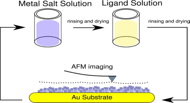
Overview of growth and imaging process used in this experiment.
After each cycle of immersion in metal and ligand solutions the substrates were returned to the AFM for further imaging. The optics of the AFM were used to align the cantilever with the registration mark to an accuracy in the range 10–20 μm. The region of interest was found through further alignment using the grain structure and terrace morphology on the Au(111) surface acquired in previous scans to provide registration. This process was then repeated for the desired number of cycles.
Films of HKUST-1 on polycrystalline Au were prepared (Figure 1) using the same preparative and sequential dipping processes on wafers of 300 nm Au on Si(100) with a 50 nm Ti bonding layer (Georg Albert PVD). In the case of the polycrystalline Au, the lack of an easily identifiable grain structure and the isotropy of the Au surface structure prevented the repeated imaging of the same area.
STM and AFM images were processed using WSxM42 and Gwyddion43 software packages. The images and data on which this paper are based are publicly available.44
Results and Discussion
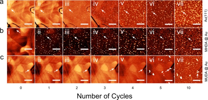
Figure 2 shows AFM images at different stages of the growth process on various thiol-terminated Au(111)/mica substrates. Each row shows a sequence of images acquired for Au(111) substrates prepared in different ways: the top row (Figure 2a) is a clean Au(111) surface; in the second row (Figure 2b) the Au(111) surface is pretreated with MHDA to give a −COOH termination; in the bottom row (Figure 2c) the Au(111) surface has an −OH termination through pretreatment with MUDA. Within each row AFM images are presented of the surface prior to deposition of the MOF in the left-hand column, followed by images acquired after, running from left to right, 1, 2, 3, 4, 5, and 10 cycles of sequential dipping. Thus, a comparison of images within a row provides a comparison of surfaces at different stages of growth, while the columns provide a comparison of images acquired after the same cycle of growth but with different surface functionalization.
Figure 2.
AFM images of HKUST-1 growth on (a) Au(111), (b) MHDA on Au(111), and (c) MUDA on Au(111) at different stages during the growth process; the number of cycles of growth is shown along the horizontal axis and varies from 0 (i) to 10 (vii). The arrows in the images a–c parts i–vii indicate specific surface features to provide registry between successive images. All scale bars are 1 μm.
The use of registration marks to obtain images of the same region of the surface is highlighted in, for example Figure 2a(i,ii) and Figure 2c(i–iv). In these images the terrace structure of the gold surface may be readily resolved and, further, the detail of this structure is immediately recognizable in successive images (across the rows). As the MOF layers grow in the subsequent dipping cycles, the contrast in the images is dominated by the MOF crystallites when their height is greater than the variation in height of the underlying gold surface (typically less than 2 nm over a 1 μm2 area from AFM data of clean Au(111) surfaces). The terrace structure is not immediately visible in such images (see for example Figure 2a(iii–vii)), although it may be readily discerned in processed images. To aid the identification of the registry in Figure 2, particularly for surfaces where there has been significant growth, we include on each image an arrow identifying a specific surface feature as a reference. Note that the loss of contrast of the gold terraces provides an approximate indication of the point where there has been significant SURMOF growth. The images therefore highlight the differing growth rates due to surface functionality with the MUDA surface having little growth until at least five cycles, whereas in the case of the MHDA terminated surface the loss of contrast occurs after a single cycle indicating significant growth has already occurred.
Interestingly, we also reproducibly observe HKUST-1 growth on the bare Au(111) metal surface as shown in Figure 2a. There have been several reports that MOF growth on bare (i.e., in the absence of functionalization by thiol SAMs) gold does not occur, for example in attempts to grow MOF-545 under solvothermal conditions,15 or HKUST-1 using the LBL technique on a polycrystalline Au surface,17 but our results confirm that growth of HKUST-1 is possible on Au(111).
In Figure 3 we show some simple statistics characterizing the growth on these surfaces. Figure 3a shows the fraction of the surface covered by the growing MOF film with increasing cycles of growth. For the −COOH terminated surface there is already >5% coverage after 1 cycle and this value increases monotonically over subsequent cycles, although the rate of increase drops between 5 and 10 cycles when the overall surface coverage is >50%. On the unfunctionalized Au(111) surface there is very little growth after one cycle and the subsequent rate of increase of surface coverage is also lower than for the −COOH surface. For the −OH terminated Au(111) surface there is still a very low fraction of the surface covered even after four growth cycles; after which the coverage increases very rapidly. These data confirm that growth occurs immediately for the −COOH terminated surface, much more slowly for the −OH terminated surface, while the clean Au(111) is an intermediate case.
Figure 3.
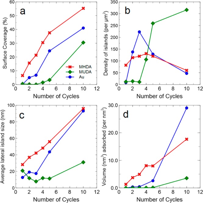
(a) Surface coverage, (b) island density, (c) average lateral island size, and (d) volume of material per unit area (or equivalently average thickness) deposited during the growth process plotted as a function of the number of growth cycles.
There are further differences in the morphology of the growing surface, for example related to the number of nucleated islands of MOF crystallites. In Figure 3b, we show the number of MOF islands per unit area. For the −COOH terminated surface there are ∼80 islands per square micron after one cycle corresponding to an average center–center island separation of ∼110 nm. This increases to ∼130 islands μm–2 after 4 cycles, which then decreases after further cycles indicating that islands have started to merge at this point. The island density on the clean Au(111) follows a similar dependence with a value which falls after 5 cycles. The growth on the −OH terminated surface differs markedly with very few islands after three cycles followed by a sharp increase in areal density.
From the data in Figure 3, parts a and b, we derive the average lateral island size (Figure 3c). From our AFM images it is also possible to estimate the total volume of material deposited and this is shown in Figure 3d as a volume measured in nm3 adsorbed per area (in nm2) of substrate (equivalent to the average height of the film in nanometres). For the −COOH terminated surface we observe a near-linear increase in both the island size and the total volume of material deposited. This implies that for this surface a near constant amount of material is added in each growth cycle, consistent with previous studies of polycrystalline gold terminated by −COOH.23,28,36 From the gradient of the data in Figure 3d) we estimate a growth rate (averaged across the sample) of ∼1.7 nm per cycle, which is much greater than the thickness of a single Cu/TMA layer, ∼ 0.6 nm (the lattice constant of the unit cell of cubic HKUST-1, which contains four layers of Cu/TMA is 2.6 nm;28 note that in ref (28) a “cycle” is defined as two immersions in the metal and ligand, rather than a single immersion in each solution as adopted here, so that in ref (28) the expected growth rate within the layer-by-layer model is 1.3 nm/cycle for a “half-layer” comprising two layers of metal ions and two layers of molecules). In previous work a constant growth rate has been interpreted as supporting evidence for layer-by-layer growth in the direction perpendicular to the substrate,23,34,36 but it is clear that in this case a constant growth rate occurs in combination with the locally accelerated growth of nanocrystallites, rather than an extended even growth of homogeneous layers.
The growth rate on the −OH terminated surface is much lower compared with the case of the −COOH terminated substrate and, in agreement with previous studies,2,36,38 more nonlinear. This results in a more inhomogeneous distribution of island sizes leading to, after 10 growth cycles, a combination of a small number of large crystallites and a large number of very small crystallites. Growth on the clean Au(111) surface is also rather nonlinear. Overall our results indicate that nucleation of MOF on these surfaces does not occur immediately but is likely preceded by an accumulation of physisorbed material, possibly mediated by inhomogeneities on the surface. We therefore focus our discussion on the −COOH surface on which, as we show below, we can monitor the progressive growth of individual crystallites. This is also the most common choice of termination for growth of HKUST-115,19,23−25,28,37,40 on surfaces.
Figure 4 shows images (Figure4a–d) of a single 1 μm2 region on MHDA terminated Au(111) acquired over 4 stages of the growth process, together with selected height profiles (Figure4e–h) which are extracted from the same positions in successive AFM images (shown as colorised lines in Figure 4a–d). These images confirm unequivocally that we are able to image the same area on the substrate due to the presence of identical, growing features, for example the two bright (topographically high) features close to the top of each image.
Figure 4.
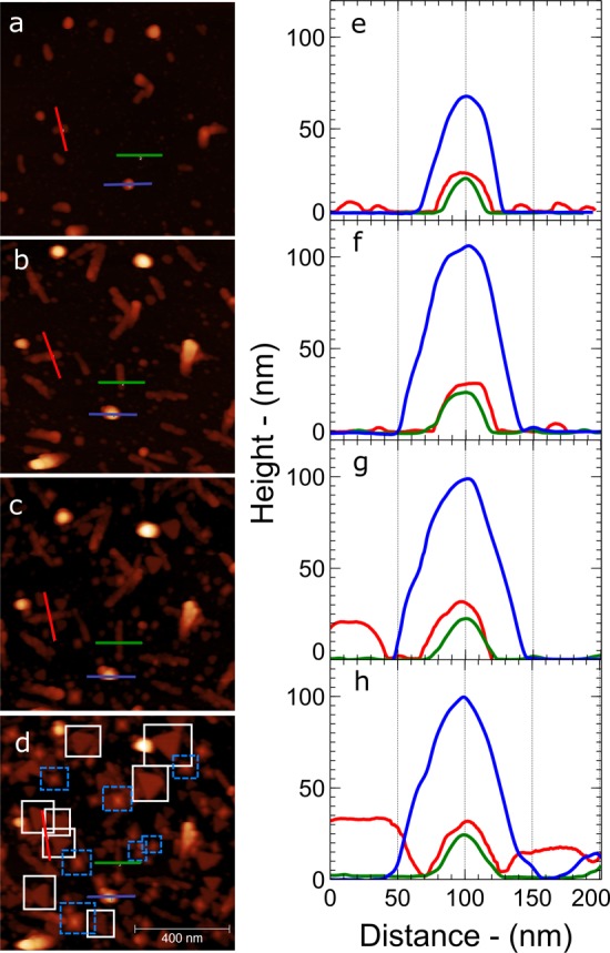
AFM images of the same 1 μm2 region on an MHDA functionalized Au(111) region shown in Figure 2 b at (a) 1, (b) 3, (c) 5, and (d) 10 cycles of growth, respectively. The blue and white boxes in part d correspond to [111] and [100] oriented crystallites respectively that can be traced throughout the entire growth process. (e–h) Line profiles across the features illustrated in parts a–d, respectively, showing the growth of material across this region.
We identify four distinct types of surface feature; the first of these are high features with a near circular shape and no obvious faceting. Examples include the islands mentioned above and also the feature through which a blue line passes; the blue height profiles are acquired along this trajectory and show the height of these islands. Surprisingly even after one growth cycle the profile indicates a height, and apparent width, of ∼65 nm. This feature grows so that after three cycles (Figure 4b,f) the height is ∼110 nm; the vertical size of this island is approximately constant after this cycle. It is possible that this feature corresponds to a noncrystalline material, or a three-dimensional aggregate, since there are no obvious facets as expected for a crystallite. We have investigated control samples which were exposed to only the metal, or only the ligand; from these controls it is clear that all the features which we observe are formed only after immersion in both the metal and the ligand, ruling out the possibility that any features are due to one of these single components.
We also observe linear islands; see for example Figure 4b where many linear features are observed. A comparison with the surface earlier (Figure 4a) and later (Figure 4c) in the growth process shows that these features grow rapidly in one lateral direction in the first few growth cycles (they are clearly present, but shorter in Figure 4a). However, after an initial stage of growth the sizes of these features saturate at a typical length of ∼150 nm and, from the profiles, a width of ∼50 nm and a height of ∼30 nm (see green and red profiles).
The other two types of surface features are highly faceted with either a triangular or square base. These features are seen most clearly in Figure 4d where they are identified with white (triangular) or blue (square) outlines. Unlike the linear and globular features, these crystallites become progressively larger through the cycles of growth; their size increases and does not saturate. For example, the red profile in Figure 4 extends over two triangular islands on either side of the linear island on which the profile is centered; these triangular islands become higher and wider as the growth progresses.
As we show below, the pyramidal features correspond to [100] oriented islands terminated by {111} planes, while the triangles correspond to [111] oriented crystallites, also terminated by {111} surfaces. It is possible to identify all of these features at earlier stages of growth (for example the triangular features in Figure 4c, and, more difficult to resolve on the scale of these images, Figure 4b).
To highlight the “history” of a particular crystallite we show in Figure 5a the progressive growth of a pyramidal (upper row) and triangular (lower row) crystallite. The square and triangular bases of these structures are very clearly resolved after 10 growth cycles and it is possible to track these features back to earlier stages in their growth; the faceted shape is apparent after 3 cycles, but is poorly resolved after 2 cycles. After 1 cycle, we can resolve the presence of a nucleated island but the shape cannot be identified with confidence at this stage.
Figure 5.
(a) AFM images of two crystallites highlighted in Figure 1d) after successive growth steps; (b) plot of the height for each crystallite in part a vs the number of growth cycles with a linear fit to the data measured from line profiles across the crystallites relative to the surrounding substrate.
These images allow the determination of the growth rate of individual crystallites which complements the average growth rates discussed above. In Figure 6, we show the variation of height with growth cycle for the square and triangular islands highlighted in Figure 4d. Although there is some variation between individual crystallites the rate of increase in height is 4.9 nm per cycle and 3.2 nm per cycle for the square and triangular islands, respectively. Again, we emphasize that this is not consistent with a model in which the growing interface advances uniformly by one layer per cycle.
Figure 6.
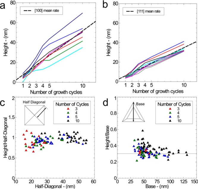
(a) Height as a function of growth cycles for individual [100] oriented HKUST-1 crystallites measured by AFM and (b) for [111] type crystallites; (c) height vs width (see inset for location of measurement) for [100] type crystallites and (d) height vs width for [111] type crystallites.
We attribute the exposed facets for both island shapes to {111} planes given their triangular symmetry; in addition this is consistent with the formation of free surfaces of bulk HKUST-1 crystals by {111} planes.37,46−48 The geometry of the square features is consistent with a crystallite growing with the [100] direction oriented normal to the surface, leading to a pyramidal structure (a square base formed by a {100} plane and four faces formed by {111} planes; see for example ref (48)). The ratio of height to the half-diagonal width of the base is expected to be 1:1 for a face centered cubic crystallite with this geometry. This is consistent with observations shown in Figure 6c, where this ratio is plotted for the square islands highlighted in Figure 4d at different stages of their growth. The presence of a [100] orientation is consistent with previous data for HKUST-1 grown on polycrystalline Au substrates functionalized with COOH end groups.17,38
We assign the triangular features to [111] oriented crystallites terminated by a {111} surface. For these crystallites the growing surface is near parallel to the substrate, but we do not see a preferred in-plane orientation implying that there is no epitaxial relationship with Au(111) surface. The presence of these [111] crystallites is not expected from previous studies of HKUST-1 on MHDA terminated Au. However, in these previous studies24,26,36,40 polycrystalline gold films were used as substrates, rather than the oriented gold films used here. To check whether this difference is significant we have investigated a surface grown using the protocols described above on MHDA-terminated polycrystalline gold. The results, shown in Figure 7, indicate the presence of many islands with typical dimensions 5–40 nm which have a faceted shape similar to that of the pyramidal [100] oriented islands discussed above, but the triangular islands are not observed; this observation is consistent with previous work17 showing the selective growth of [100] crystallites on similar surfaces and other recent AFM studies.49 The pyramidal shape implies that these crystallites are terminated by {111} planes.
Figure 7.
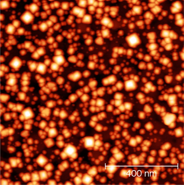
AFM image of 10 cycles of growth of HKUST-1 on polycrystalline Au on Si coated with MHDA. The AFM image shows a predominantly square based pyramid nanocrystallite structure indicating a preferential [100] orientation normal to the surface in agreement with the literature.
Conclusions
The growth of HKUST-1 on Au(111)/mica islands shows significant differences to previous work using polycrystalline gold substrates. First, we observe some growth even on clean Au(111)/mica, but the more interesting effects relate to growth on the MHDA-terminated surface which introduces a −COOH functionality. Here we observe the growth of four distinct types of island of which two may be readily identified as [100] and [111] oriented crystallites. Using AFM it is possible to measure not only the average growth rate across the surface, but also the local growth rate both horizontally and vertically to the surface for individual crystallites. Both these rates are greater than one layer/per cycle, while the local increase in height per cycle, measured to be 4.9 and 3.2 nm for, respectively, [100] and [111] type crystallites, is significantly greater than the thickness of a single Cu/TMA layer, ∼0.6 nm. This observation demonstrates that in local regions of the surface multiple (5–10) layers of MOF are grown in each cycle.
Interestingly the largest crystalline features which are identified in Figure 5d may be traced all the way back to the first deposition step in Figure 4a. This implies that the nucleation of all these islands has already occurred after the first cycle of growth. Furthermore, we can address the question of whether the growing crystallites are redissolved or significantly redistributed when the substrates are reimmersed in the relevant solutions. The reproducible appearance of growing islands and traceability of the location of structures on this highly inhomogeneous surface implies that very little reorganization or solvent-assisted recrystallization of material occurs under the conditions used here.
For HKUST-1 grown on polycrystalline gold, we observe significant differences; the lateral size of individual crystallites is considerably smaller, and we do not observe triangular islands. The larger crystallite size on Au(111)/mica may be due to the presence of larger, flatter terraces, as compared to the rougher evaporated gold surfaces on which we observe a higher density of nucleated islands, and thus smaller crystallites. This enhancement in nucleation density may be due to inhomogeneities in the gold film, or in the MHDA termination. However, our observation of oriented [100] growth is consistent with previous studies of thicker film growth on this surface.
The termination of the faceted crystallites by {111} planes of HKUST-1 is observed for both the [100] and [111] crystallites, and, in addition, for the pyramidal shapes resolved on polycrystalline gold. As stated above, the free and therefore lowest energy, surfaces of bulk HKUST-1 crystals are formed by {111} planes, and the termination of the SURMOFs by these same planes is therefore expected. This implies that for growth under near-equilibrium conditions, for which the lowest energy surface will dominate, the growing interface is only parallel to the substrate surface if the crystallographic orientation is normal to the lowest energy surface plane. This is observed for the triangular [111] oriented islands, but not for the pyramidal [100] crystallites and implies that the growing interface of [100] crystallites on both Au(111) and polycrystalline gold, cannot be parallel to the substrate. Our AFM results also show that under these conditions the rate of propagation of the growing interface is not homogeneous across a surface, and that local rates vary significantly. Accordingly the incorporation of single layers of MOF cannot be inferred from rates averaged across a surface measured, for example, using a QCM to measure mass uptake.
The results presented here highlight the very significant contribution that high resolution AFM can contribute to the understanding of SURMOF growth and in particular to monitor the local growth of individual crystallites from the very early stages of nucleation. It is clear that this AFM approach allows us to determine whether the layer-by-layer method for SURMOF growth is valid under the conditions used here; we find that it is not and observe nanocrystalline growth. We hope that these results will motivate other working in the field to adopt this technique to evaluate other SURMOFs to provide a rigorous test of the assumptions of the layer-by-layer method. Our results suggest that this approach to growth would be best suited to materials for which it is possible to select, for example using self-assembled monolayers, a crystallographic orientation that is normal to the lowest energy surface of the MOF. Under these circumstances, the growing interface might be selected to be parallel to the substrate.
Acknowledgments
We thank the U.K. Engineering and Physical Sciences Research Council for funding under Grant EP/I011870/1. M.S. thanks the European Research Council for support (Advanced Grant).
Supporting Information Available
This material can be found online free of charge at The Supporting Information is available free of charge on the ACS Publications website at DOI: 10.1021/acs.jpcc.5b07133.
Author Present Address
⊥ Department of Chemistry, University of Manchester, Manchester, M13 9PL, UK
The authors declare no competing financial interest.
Supplementary Material
References
- Chui S. S.-Y. Y.; Lo S. M.-F. F.; Charmant J. P. H.; Orpen A. G.; Williams I. D. A Chemically Functionalizable Nanoporous Material [Cu3(TMA)2(H2O)3]n. Science 1999, 283, 1148–1150 10.1126/science.283.5405.1148. [DOI] [PubMed] [Google Scholar]
- Shekhah O.; Liu J.; Fischer R. A.; Wöll C. MOF Thin Films: Existing and Future Applications. Chem. Soc. Rev. 2011, 40, 1081–1106 10.1039/c0cs00147c. [DOI] [PubMed] [Google Scholar]
- Liu J.; Lukose B.; Shekhah O.; Arslan H. K.; Weidler P.; Gliemann H.; Bräse S.; Grosjean S.; Godt A.; Feng X.; et al. A Novel Series of Isoreticular Metal Organic Frameworks: Realizing Metastable Structures by Liquid Phase Epitaxy. Sci. Rep. 2012, 2, 921. 10.1038/srep00921. [DOI] [PMC free article] [PubMed] [Google Scholar]
- Lin X.; Jia J.; Zhao X.; Thomas K. M.; Blake A. J.; Walker G. S.; Champness N. R.; Hubberstey P.; Schröder M. High H2 Adsorption by Coordination-Framework Materials. Angew. Chem., Int. Ed. 2006, 45, 7358–7364 10.1002/anie.200601991. [DOI] [PubMed] [Google Scholar]
- Deng H.; Grunder S.; Cordova K. E.; Valente C.; Furukawa H.; Hmadeh M.; Gándara F.; Whalley A. C.; Liu Z.; Asahina S.; et al. Large-Pore Apertures in a Series of Metal-Organic Frameworks. Science 2012, 336, 1018–1023 10.1126/science.1220131. [DOI] [PubMed] [Google Scholar]
- Bétard A.; Fischer R. A. Metal-Organic Framework Thin Films: From Fundamentals to Applications. Chem. Rev. 2012, 112, 1055–1083 10.1021/cr200167v. [DOI] [PubMed] [Google Scholar]
- Silva C. G.; Corma A.; García H. Metal–organic Frameworks as Semiconductors. J. Mater. Chem. 2010, 20, 3141–3156 10.1039/b924937k. [DOI] [Google Scholar]
- Ma L.; Abney C.; Lin W. Enantioselective Catalysis with Homochiral Metal–organic Frameworks. Chem. Soc. Rev. 2009, 38, 1248–1256 10.1039/b807083k. [DOI] [PubMed] [Google Scholar]
- Choi K. M.; Jeong H. M.; Park J. H.; Zhang Y. B.; Kang J. K.; Yaghi O. M. Supercapacitors of Nanocrystalline Metal-Organic Frameworks. ACS Nano 2014, 8, 7451–7457 10.1021/nn5027092. [DOI] [PubMed] [Google Scholar]
- Talin A. A.; Centrone A.; Ford A. C.; Foster M. E.; Stavila V.; Haney P.; Kinney R. A.; Szalai V.; El Gabaly F.; Yoon H. P.; et al. Tunable Electrical Conductivity in Metal-Organic Framework Thin-Film Devices. Science 2014, 343, 66–69 10.1126/science.1246738. [DOI] [PubMed] [Google Scholar]
- Yoon S. M.; Warren S. C.; Grzybowski B. A. Storage of Electrical Information in Metal-Organic-Framework Memristors. Angew. Chem., Int. Ed. 2014, 53, 4437–4441 10.1002/anie.201309642. [DOI] [PubMed] [Google Scholar]
- Redel E.; Wang Z.; Walheim S.; Liu J.; Gliemann H.; Wöll C. On the Dielectric and Optical Properties of Surface-Anchored Metal-Organic Frameworks: A Study on Epitaxially Grown Thin Films. Appl. Phys. Lett. 2013, 103, 091903. 10.1063/1.4819836. [DOI] [Google Scholar]
- Allendorf M. D.; Schwartzberg A.; Stavila V.; Talin A. A. A Roadmap to Implementing Metal-Organic Frameworks in Electronic Devices: Challenges and Critical Directions. Chem. - Eur. J. 2011, 17, 11372–11388 10.1002/chem.201101595. [DOI] [PubMed] [Google Scholar]
- Hermes S.; Zacher D.; Baunemann A.; Wöll C.; Fischer R. A. Selective Growth and MOCVD Loading of Small Single Crystals of MOF-5 at Alumina and Silica Surfaces Modified with Organic Self-Assembled Monolayers. Chem. Mater. 2007, 19, 2168–2173 10.1021/cm062854+. [DOI] [Google Scholar]
- Hermes S.; Schröder F.; Chelmowski R.; Wöll C.; Fischer R. A. Selective Nucleation and Growth of Metal-Organic Open Framework Thin Films on Patterned COOH/CF3-Terminated Self-Assembled Monolayers on Au(111). J. Am. Chem. Soc. 2005, 127, 13744–13745 10.1021/ja053523l. [DOI] [PubMed] [Google Scholar]
- Bradshaw D.; Garai A.; Huo J. Metal–organic Framework Growth at Functional Interfaces: Thin Films and Composites for Diverse Applications. Chem. Soc. Rev. 2012, 41, 2344–2381 10.1039/C1CS15276A. [DOI] [PubMed] [Google Scholar]
- Biemmi E.; Scherb C.; Bein T. Oriented Growth of the Metal Organic Framework Cu(3) (BTC)(2)(H(2)O)(3).xH(2)O Tunable with Functionalized Self-Assembled Monolayers. J. Am. Chem. Soc. 2007, 129, 8054–8055 10.1021/ja0701208. [DOI] [PubMed] [Google Scholar]
- Falcaro P.; Ricco R.; Doherty C. M.; Liang K.; Hill A. J.; Styles M. J. MOF Positioning Technology and Device Fabrication. Chem. Soc. Rev. 2014, 43, 5513–5560 10.1039/C4CS00089G. [DOI] [PubMed] [Google Scholar]
- Zacher D.; Baunemann A.; Hermes S.; Fischer R. A. Deposition of Microcrystalline [Cu3(btc)2] and [Zn2(bdc)2(dabco)] at Alumina and Silica Surfaces Modified with Patterned Self Assembled Organic Monolayers: Evidence of Surface Selective and Oriented Growth. J. Mater. Chem. 2007, 17, 2785–2792 10.1039/b703098c. [DOI] [Google Scholar]
- Ladnorg T.; Welle A.; Heißler S.; Wöll C.; Gliemann H. Site-Selective Growth of Surface-Anchored Metal-Organic Frameworks on Self-Assembled Monolayer Patterns Prepared by AFM Nanografting. Beilstein J. Nanotechnol. 2013, 4, 638–648 10.3762/bjnano.4.71. [DOI] [PMC free article] [PubMed] [Google Scholar]
- Zacher D.; Shekhah O.; Wöll C.; Fischer R. A. Thin Films of Metal-Organic Frameworks. Chem. Soc. Rev. 2009, 38, 1418–1429 10.1039/b805038b. [DOI] [PubMed] [Google Scholar]
- Wang M.-S.; Guo S.-P.; Li Y.; Cai L.-Z.; Zou J.-P.; Xu G.; Zhou W.-W.; Zheng F.-K.; Guo G.-C. A Direct White-Light-Emitting Metal-Organic Framework with Tunable Yellow-to-White Photoluminescence by Variation of Excitation Light. J. Am. Chem. Soc. 2009, 131, 13572–13573 10.1021/ja903947b. [DOI] [PubMed] [Google Scholar]
- Shekhah O.; Wang H.; Strunskus T.; Cyganik P.; Zacher D.; Fischer R. A.; Wöll C. Layer-by-Layer Growth of Oriented Metal Organic Polymers on a Functionalized Organic Surface. Langmuir 2007, 23, 7440–7442 10.1021/la701148z. [DOI] [PubMed] [Google Scholar]
- Shekhah O.; Wang H.; Kowarik S.; Schreiber F.; Paulus M.; Tolan M.; Sternemann C.; Evers F.; Zacher D.; Fischer R. A; et al. Step-by-Step Route for the Synthesis of Metal-Organic Frameworks. J. Am. Chem. Soc. 2007, 129, 15118–15119 10.1021/ja076210u. [DOI] [PubMed] [Google Scholar]
- Stavila V.; Volponi J.; Katzenmeyer A. M.; Dixon M. C.; Allendorf M. D. Kinetics and Mechanism of Metal–organic Framework Thin Film Growth: Systematic Investigation of HKUST-1 Deposition on QCM Electrodes. Chem. Sci. 2012, 3, 1531–1540 10.1039/c2sc20065a. [DOI] [Google Scholar]
- Arslan H. K.; Shekhah O.; Wohlgemuth J.; Franzreb M.; Fischer R. A.; Wöll C. High-Throughput Fabrication of Uniform and Homogenous MOF Coatings. Adv. Funct. Mater. 2011, 21, 4228–4231 10.1002/adfm.201101592. [DOI] [Google Scholar]
- Gliemann H.; Wöll C. Epitaxially Grown Metal-Organic Frameworks. Mater. Today 2012, 15, 110–116 10.1016/S1369-7021(12)70046-9. [DOI] [Google Scholar]
- Munuera C.; Shekhah O.; Wang H.; Wöll C.; Ocal C. The Controlled Growth of Oriented Metal-Organic Frameworks on Functionalized Surfaces as Followed by Scanning Force Microscopy. Phys. Chem. Chem. Phys. 2008, 10, 7257–7261 10.1039/b811010g. [DOI] [PubMed] [Google Scholar]
- Shekhah O.; Hirai K.; Wang H.; Uehara H.; Kondo M.; Diring S.; Zacher D.; Fischer R. A.; Sakata O.; Kitagawa S.; et al. MOF-on-MOF Heteroepitaxy: Perfectly Oriented [Zn2(ndc)2(dabco)]n Grown on [Cu2(ndc)2(dabco)]n Thin Films. Dalton Trans. 2011, 40, 4954–4958 10.1039/c0dt01818j. [DOI] [PubMed] [Google Scholar]
- Heinke L.; Cakici M.; Dommaschk M.; Grosjean S.; Herges R.; Bräse S.; Wöll C. Photoswitching in Two-Component Surface-Mounted Metal-Organic Frameworks: Optically Triggered Release from a Molecular Container. ACS Nano 2014, 8, 1463–1467 10.1021/nn405469g. [DOI] [PubMed] [Google Scholar]
- Otsubo K.; Haraguchi T.; Sakata O.; Fujiwara A.; Kitagawa H. Step-by-Step Fabrication of a Highly Oriented Crystalline Three-Dimensional Pillared-Layer-Type Metal-Organic Framework Thin Film Confirmed by Synchrotron X-Ray Diffraction. J. Am. Chem. Soc. 2012, 134, 9605–9608 10.1021/ja304361v. [DOI] [PubMed] [Google Scholar]
- Liu B.; Ma M.; Zacher D.; Bétard A.; Yusenko K.; Metzler-Nolte N.; Wöll C.; Fischer R. A. Chemistry of SURMOFs: Layer-Selective Installation of Functional Groups and Post-Synthetic Covalent Modification Probed by Fluorescence Microscopy. J. Am. Chem. Soc. 2011, 133, 1734–1737 10.1021/ja1109826. [DOI] [PubMed] [Google Scholar]
- Shekhah O.; Arslan H. K.; Chen K.; Schmittel M.; Maul R.; Wenzel W.; Wöll C. Post-Synthetic Modification of Epitaxially Grown, Highly Oriented Functionalized MOF Thin Films. Chem. Commun. 2011, 47, 11210–11212 10.1039/c1cc12543e. [DOI] [PubMed] [Google Scholar]
- Zacher D.; Yusenko K.; Bétard A.; Henke S.; Molon M.; Ladnorg T.; Shekhah O.; Schüpbach B.; de Los Arcos T.; Krasnopolski M.; et al. Liquid-Phase Epitaxy of Multicomponent Layer-Based Porous Coordination Polymer Thin Films of [M(L)(P)0.5] Type: Importance of Deposition Sequence on the Oriented Growth. Chem. - Eur. J. 2011, 17, 1448–1455 10.1002/chem.201002381. [DOI] [PubMed] [Google Scholar]
- Tu M.; Fischer R. A. Heteroepitaxial Growth of Surface Mounted Metal–organic Framework Thin Films with Hybrid Adsorption Functionality. J. Mater. Chem. A 2014, 2, 2018–2022 10.1039/C3TA13812G. [DOI] [Google Scholar]
- Shekhah O. Layer-by-Layer Method for the Synthesis and Growth of Surface Mounted Metal-Organic Frameworks (SURMOFS). Materials 2010, 3, 1302–1315 10.3390/ma3021302. [DOI] [Google Scholar]
- Szelagowska-Kunstman K.; Cyganik P.; Goryl M.; Zacher D.; Puterova Z.; Fischer R. A.; Szymonski M. Surface Structure of Metal-Organic Framework Grown on Self-Assembled Monolayers Revealed by High-Resolution Atomic Force Microscopy. J. Am. Chem. Soc. 2008, 130, 14446–14447 10.1021/ja8069743. [DOI] [PubMed] [Google Scholar]
- Shekhah O.; Wang H.; Zacher D.; Fischer R. A.; Wöll C. Growth Mechanism of Metal-Organic Frameworks: Insights into the Nucleation by Employing a Step-by-Step Route. Angew. Chem., Int. Ed. 2009, 48, 5038–5041 10.1002/anie.200900378. [DOI] [PubMed] [Google Scholar]
- Lu G.; Hupp J. T. Metal-Organic Frameworks as Sensors: A ZIF-8 Based Fabry-Pérot Device as a Selective Sensor for Chemical Vapors and Gases. J. Am. Chem. Soc. 2010, 132, 7832–7833 10.1021/ja101415b. [DOI] [PubMed] [Google Scholar]
- Liu J.; Shekhah O.; Stammer X.; Arslan H. K.; Liu B.; Schüpbach B.; Terfort A.; Wöll C. Deposition of Metal-Organic Frameworks by Liquid-Phase Epitaxy: The Influence of Substrate Functional Group Density on Film Orientation. Materials 2012, 5, 1581–1592 10.3390/ma5091581. [DOI] [Google Scholar]
- Shen C.; Cebula I.; Brown C.; Zhao J.; Zharnikov M.; Buck M. Structure of Isophthalic Acid Based Monolayers and Its Relation to the Initial Stages of Growth of Metal–organic Coordination Layers. Chem. Sci. 2012, 3, 1858–1865 10.1039/c2sc20087b. [DOI] [Google Scholar]
- Horcas I.; Fernández R.; Gómez-Rodríguez J. M.; Colchero J.; Gómez-Herrero J.; Baro A. M.; Fernandez R.; Gomez-Rodriguez J. M.; Gomez-Herrero J. WSXM: A Software for Scanning Probe Microscopy and a Tool for Nanotechnology. Rev. Sci. Instrum. 2007, 78, 013705. 10.1063/1.2432410. [DOI] [PubMed] [Google Scholar]
- Nečas D.; Klapetek P. Gwyddion: An Open-Source Software for SPM Data Analysis. Cent. Eur. J. Phys. 2012, 10, 181–188 10.2478/s11534-011-0096-2. [DOI] [Google Scholar]
- The data, including image files, on which this paper is based are available at http://dx.doi.org/10.17639/nott.25 (date of access 23rd September 2015).
- Li H.; Eddaoudi M.; O’Keeffe M.; Yaghi O. Design and Synthesis of an Exceptionally Stable and Highly Porous Metal-Organic Framework. Nature 1999, 402, 276–279 10.1038/46248. [DOI] [Google Scholar]
- Zhuang J.-L.; Ceglarek D.; Pethuraj S.; Terfort A. Rapid Room-Temperature Synthesis of Metal-Organic Framework HKUST-1 Crystals in Bulk and as Oriented and Patterned Thin Films. Adv. Funct. Mater. 2011, 21, 1442–1447 10.1002/adfm.201002529. [DOI] [Google Scholar]
- John N. S.; Scherb C.; Shöâeè M.; Anderson M. W.; Attfield M. P.; Bein T. Single Layer Growth of Sub-Micron Metal-Organic Framework Crystals Observed by in Situ Atomic Force Microscopy. Chem. Commun. 2009, 2, 6294–6296 10.1039/b908299a. [DOI] [PubMed] [Google Scholar]
- Amirjalayer S.; Tafipolsky M.; Schmid R. Surface Termination of the Metal-Organic Framework HKUST-1: A Theoretical Investigation. J. Phys. Chem. Lett. 2014, 5, 3206–3210 10.1021/jz5012065. [DOI] [PubMed] [Google Scholar]
- Ohnsorg M. L.; Beaudoin C. K.; Anderson M. E. Fundamentals of MOF Thin Film Growth via Liquid-Phase Epitaxy: Investigating the Initiation of Deposition and the Influence of Temperature. Langmuir 2015, 31, 6114–6121 10.1021/acs.langmuir.5b01333. [DOI] [PubMed] [Google Scholar]
Associated Data
This section collects any data citations, data availability statements, or supplementary materials included in this article.


