Short abstract
The present work describes the design of a device/system intended to induce local mild hypothermia by simultaneously cooling a patient's head and neck. The therapeutic goal is to lower the head and neck temperatures to 33–35 °C, while leaving the core body temperature unchanged. The device works by circulating a cold fluid around the exterior of the head and neck. The head surface area is separated into five different cooling zones. Each zone has a cooling coil and can be independently controlled. The cooling coils are tightly wrapped concentric circles of tubing. This design allows for a dense packing of tubes in a limited space, while preventing crimping of the tubing and minimizing the fluid pressure head loss. The design in the neck region also has multiple tubes wrapping around the circumference of the patient's neck in a helix. Preliminary testing indicates that this approach is capable of achieving the design goal of cooling the brain tissue (at a depth of 2.5 cm from the scalp) to 35 °C within 30– 40 min, without any pharmacologic or circulatory manipulation. In a comparison with examples of current technology, the device has shown the potential for improved cooling capability.
Keywords: hypothermia, cooling helmet, stroke, traumatic brain injury, neuroprotection
Introduction
Therapeutic hypothermia (TH) is considered to be an important treatment option in the acute setting for neurological injuries that may improve survival with a favorable neurological outcome [1,2]. In recent years, a great amount of research has been conducted regarding the primary effects of inducing mild hypothermia, which is defined as a tissue target temperature (TT) of 33–35 °C, in ischemic stroke or traumatic brain injury (TBI) patients [3–12]. Moreover, preclinical and clinical studies have been conducted to investigate the effects of TH with promising results [8,13,14]. Nevertheless, the exact underlying effects of induced clinical hypothermia as a neuroprotection are still under investigation [8]. Cranial hypothermia may reduce neuronal damage from excitotoxins, apoptosis, and inflammation [13,15–18].
In several animal studies, the use of TH has resulted in a reduction of the infarct size associated with cerebral ischemia [19,20]. Furthermore, the use of TH alone or in combination with thrombolysis has been shown to produce higher survival rates with preclinical thromboembolic stroke models [14]. In such animal studies, employing a temperature range of 28–34 °C has produced the most favorable results [8]. Although limited, there have been some promising human clinical trials showing the potential efficacy of TH around 33 °C. Lower temperatures may lead to complications that override the benefit of TH [8].
The objective of this study was to design a cooling helmet to induce local mild hypothermia to treat neurological injuries such as ischemic and hemorrhagic stroke, spinal cord injury (SCI), and TBI. The primary design goal of the device was to cool the brain tissue at a depth of about 2.5 cm to 35 °C within 30–40 min. The device must be applicable in both the hospital and prehospital environments. Other device requirements included assistance with neck immobilization and sectional cooling to obtain different cooling zone temperatures.
Current Methods for TH Induction
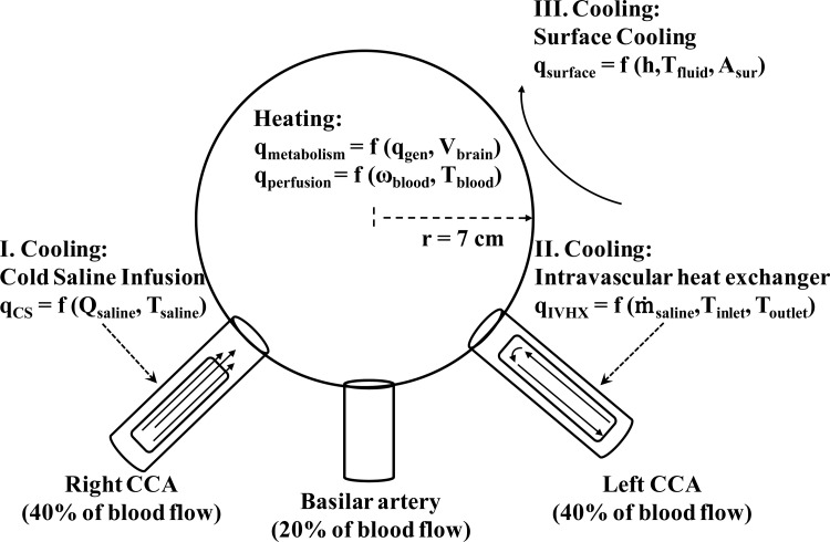
Currently, the methods utilized to induce TH are: cold saline infusion, intravascular heat exchangers, surface cooling, and a combination of cold saline infusion with surface cooling. An approximation of the cooling power and the initial cooling rates to expect with each of these methods can be determined by a scaling comparison and a simplified head model. As shown by Fig. 1, the head is modeled as a sphere with the same volume, thermal conductivity, density, and specific heat as the human brain. The average adult male brain is about 1500 g [21], which corresponds to a 7 cm radius sphere. The cooling powers for the cold saline infusion (CS), intravascular heat exchanger (IVHX), and surface cooling (surface) are
Fig. 1.
Schematic of the simplified head model
| (1) |
| (2) |
and
| (3) |
respectively. The heating powers of perfusion and metabolism are
| (4) |
and
| (5) |
respectively.
Table 1 compares the heating power as a function of the perfusion rate ω and metabolic heat generation q ‴ to the cooling power of the different methods. Table 1 includes the cooling power as a function of the volumetric saline infusion rate Q saline for the cold saline infusion and the heat transfer coefficient h for surface cooling. The heat transfer coefficient is expressed in terms of the Biot number (Bi). For comparison, the cooling power for a large (100) and small (1) Bi are shown.
Table 1.
Comparison of heating and cooling power
|
Heating | |||
|---|---|---|---|
| Mechanism | q (W/°C) | ω (ml/ml/s) | Comments |
| Perfusion | 20.0 | 0.0033 a | Low |
| 50.2 | 0.0083 b | Normal | |
| 80.5 | 0.0133 a | High | |
| Metabolism | q (W) | q ‴ (W/m3) | |
| 8.1 | 5725 a | White matter | |
| 11.4 | 8081 | Average | |
| 14.7 | 10,437 a | Gray matter | |
| Cooling | |||
| Method | q (W) | Q (ml/s) | |
| I. Cold saline | 55 | 0.4 | |
| 69 | 0.5 c | ||
| 104 | 0.75 | ||
| 115 | 1.0 c | ||
| II. Intravascular heat exchanger | 45 d | … | |
| 60 | … | ||
| 90 e | … | ||
| III. Surface cooling | q (W) | Bi | Comments |
| 14.5 | 1 | Low | |
| 1450 | 100 | High | |
Using the cooling powers in Table 1, the idealized initial cooling rates are calculated with the simplified head model outlined in the Appendix. For simplicity, the predicted rates for surface cooling ignore the perfusion and metabolism factors. Table 2 compares the cooling rates of the different cooling methods. The high and low predicted cooling rates in Table 2 reflect the high and low cooling power listed in Table 1 for each method. For the predicted cooling rates and cooling powers, it is assumed that the saline is injected at 4 °C. The brain temperature is initially at 37 °C. To approximate the warming effect of perfusion, the difference between arterial and brain temperatures is assumed to be 1 °C and the normal perfusion rate of Table 1 is used. These predicted cooling rates represent the maximum cooling rates. They will decrease as the brain temperature and fluid temperatures converge and as the heating power of the perfusion term increases due to the difference between the arterial blood and brain temperature.
Table 2.
Comparison of cooling rates
Table 2 also reports some of the published cooling rates for initial cooling. With the exception of the intravascular heat exchanger, the predicted cooling rates are similar to the reported cooling rates. The discrepancy between the predicted and reported cooling rates for the intravascular heat exchangers is because in studies with heat exchangers, the devices are not used at maximum capacity for patient safety. Intravascular heat exchangers allow for more precise control over the cooling rate and, thus, a prescribed cooling rate is followed when inducing hypothermia. For example, in one study [29], the cooling rate is purposely kept at only 1.4 °C/h and in a different study [30] the cooling rate is limited to 0.7 °C/h. The model shows that cold saline infusion and intravascular cooling have much higher cooling rates than surface cooling, which is also reflected in the published rates. Even ignoring perfusion and with a large Bi number, surface cooling reaches a limit at 3.4 °C/h while cold saline infusion and intravascular heat exchangers have predicted cooling rates an order of magnitude greater.
As shown by Table 1, cold saline infusion offers the benefit of the rapid attainment of TH. The model predicts head cooling rates between 7 and 50 °C/h. Whole body cooling rates between 0.4 and 18 °C/h have been reported [31]. Additionally, cold saline infusion allows for external heating to combat shivering [31]. Yet it has been suggested that the relatively large volume of liquid required to maintain TH [32] and the lack of control in maintaining a specific TT precludes cold saline infusion from being the sole means for maintaining TH for long periods of time [2].
Intravascular heat exchangers also have high cooling rates and allow for external heating to combat shivering, but they do not require the large fluid volumes of infusion [2]. The model predicts initial cooling rates of 2 to 33 °C/h. Whole body cooling rates of 1 to 7 °C/h have been reported for intravascular cooling [31]. However, intravascular cooling requires knowledge of advanced techniques such as catheterization, which has limited, especially in prehospital settings, the widespread application of these devices [31,32]. Such cooling devices also tend to be the most complicated and expensive systems [31,32].
Surface cooling is the slowest method with predicted rates of 2 to 3.4 °C/h and published rates of 1 to 2 °C/h [31–33]. The cooling rates for surface cooling improve when the target tissue is near the surface. Surface cooling is a slower cooling method due to the low thermal conductivity of skin, bone, and hair [32] and because surface cooling devices usually induce shivering and other thermoregulation defenses [2]. The perfusion of warm blood also presents a significant challenge to surface cooling [32]. Unlike intravascular cooling, surface cooling has the advantage of easy application [31]. Furthermore, the simplicity of surface cooling devices allows the initiation of cooling to begin in a prehospital setting [31]. Despite the lower cooling rates, surface cooling has been widely practiced in different forms such as cooling blankets, ice packs, or ice baths in order to obtain and maintain mild hypothermia [2,31,33–38]. For example, a head cooling device has been shown to decrease the brain temperature by 1.84 °C in one hour and to continue the cooling trend for several hours [33]. Head and neck cooling has also been shown to maintain brain temperatures of 33–35 °C for up to three days [34,35]. During cardiac arrest, surface cooling has been shown to be sufficient to maintain hypothermia in monkeys [39]. Many designs for surface cooling are available [32,37,38]. The functionality of our design is compared to other designs which report similar results.
Design Details
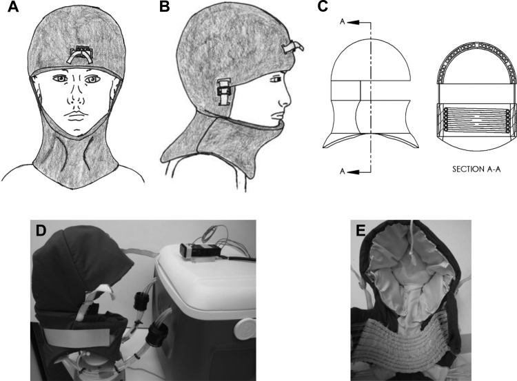
The device introduced here is a circulating fluid design, which pumps fluid (such as distilled water, normal saline, hypertonic saline, etc.) around the exterior portion of the head and neck. The device can be used in conjunction with cold saline infusion, allowing TH to be initiated by the infusion of cold saline and maintained by the device. A schematic presentation and actual images of the prototype can be seen in Fig. 2. The base station houses the pumps, a water bath that could be replaced with a refrigeration system, and electrical controls.
Fig. 2.
Cooling helmet device. (a)–(c) Schematic presentations, and (d) and (e) actual device.
The system can be broken down into two main thermal regions: the head region and the neck region. The head region contains five different cooling zones, each of which can be independently cooled. The neck region forms the sixth zone. With six independent cooling zones, the device satisfies the design goal of sectional cooling. There is also temperature feedback and a controller for each zone. Note that in this design, the individual zone controllers can be over-ridden by a master control in order to impose a total cool down, which is an element considered to be initially necessary. The sectional cooling would most likely be used in a hospital setting where more information would be available on the location of the brain injury.
Temperature control feedback is accomplished with a SL4824-RR temperature controller (AutomationDirect, Atlanta, GA). Each thermal zone has one of these dedicated controllers, so that the user can monitor each region and set a desired temperature for each zone. The controllers also provide an important safety function, since they can automatically turn off the pumps if the temperature of a region decreases below the target temperature. Moreover, this design allows for the monitoring of scalp and/or tympanic temperatures in the field, since these should not infer with the paramedics' standard operating procedures.
The helmet is designed to fit a wide range of head and neck sizes and it can be customized with a number of straps. The straps also apply a mild pressure, which is user adjustable. The mild pressure helps to bring the cooling coils into better thermal contact with the patient's scalp. The neck region has a permanent neck brace built into it to aid with neck immobilization in the event of a traumatic injury such as a spinal cord injury (SCI).
Cooling Coils
Each of the five cooling zones in the head thermal region has a separate cooling coil. These coils allow for a dense tube layout to maximize heat transfer and to help minimize fluid pressure losses due to changes in direction of the flow. These coils are currently made out of Tygon tubing because of its anticrimping qualities. Improving the thermal conductivity of the tubing (as is discussed later) would help improve the performance of the current device. The coils are made out of small diameter tubing, which allows for better articulation of the coil against the patient's head, creating better thermal contact between the cooling coil and the patient scalp. A thin tubing wall thickness was selected (0.8 mm) in order to decrease the thermal resistance of the wall. The selection of tubing is discussed in more detail in the “Design Discussion section.”
The neck thermal zone component has a slightly different “coil” system. It has a helix shape that wraps around the neck and lies inside the neck brace. Like the cooling coils in the head regions, this allows for a dense tube layout that increases the efficiency of the cooling process.
Experiment Set-Up
A head phantom was made from instant casting material and paper mâché to simulate a human head (see Fig. 3). The phantom head provided a consistent head-shaped platform upon which to test various generations of the device and to compare the heat transfer of the final prototype against a commercially available head cooling device. Note that this experimental apparatus only simulated the head region. Equation (6) is used to calculate the instantaneous heat transfer rate
Fig. 3.
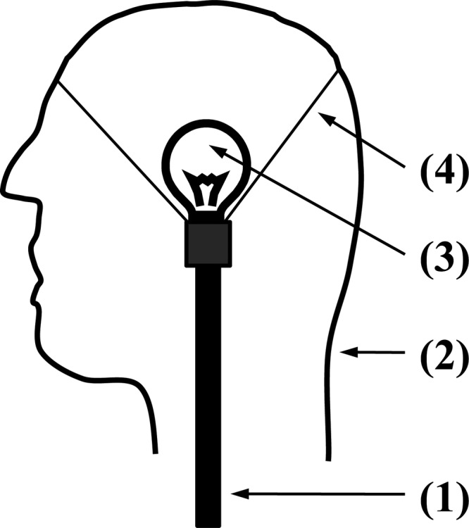
Cross-sectional schematic view of the phantom head consisting of the (1) support structure, (2) shell molded into a human head form, (3) incandescent light bulb for heat generation, and (4) support structure to the shell
| (6) |
Here, K-type thermocouples were used to measure the inlet T tank and outlet T outlet fluid temperatures.
In order to simulate the metabolic heat generation and perfusion of warm blood from the core, an incandescent light bulb was used as a heat source because it converts most of the supplied energy to heat. The power size of the light bulb was experimentally determined. Using an earlier generation prototype on a volunteer's head, the heat transfer from the head to the cooling coil was measured. Once a heat transfer rate was estimated in such a trial, it was determined that a 60 to 75 W light bulb accurately simulated the heat transfer from a human head. More specifically, with a 60 W bulb an average heat flow of 40 ± 6 W was obtained for a single coil; with the 75 Watt bulb, 55 ± 8 W was measured. In the in vivo experiment, the heat flow was 48 ± 10 W.
The present device was compared to a commercially available surface cooling device by comparing the heat transfer rates obtained on the phantom head. For each device and heat source, the temperatures were measured for 10 min. The average heat transfer rate for the 10 min experiment was calculated from the instantaneous values. The measurement was repeated twice for each device and heat source. The average of the measurements is reported at the 95% confidence interval.
A second experiment was also designed, wherein the scalp temperature of a healthy subject was monitored. The subject was seated in an upright position during the test. The device was allowed to operate for 30 min with a K-type thermocouple attached to the scalp. Once again, Eq. (6) was used to calculate the instantaneous heat transfer rate. The result of this demonstrative experiment was compared to scalp temperature measurements from other surface cooling devices.
Functionality and Comparison to Current Technology
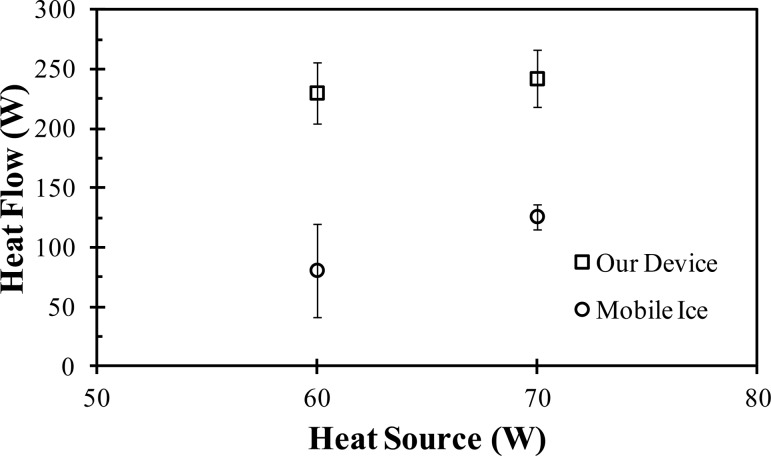
The described cooling system was evaluated using the aforementioned head phantom. The heat flow rates from the device were compared to the results of a commercially available device (Mobile Ice, Adroit Medical Systems, Loudon, TN) tested on the same head phantom. As shown by Fig. 4, our device had a significantly increased heat transfer rate compared to the Mobile Ice device. With the 60 W source, the device had an average heat flow of 230 ± 26 W compared to 81 ± 39 W for the Mobile Ice device. When using a 75 W source, the device had an average heat flow of 242 ± 24 W, as compared to 126 ± 11 W for the Mobile Ice device. In addition to the increased heat transfer, our device has sectional cooling capabilities which the Mobile Ice device does not offer. An in vivo test on a healthy subject using our device had an average heat flow of 220 W. For comparison, when using a head and neck cooling apparatus from Life Support Systems, a heat removal rate of 122 ± 2.32 W was reported [40]. Although the comparison must be made carefully until an adequate sample size is used to compare the performance of the two devices, it shows the potential for our device to improve heat transfer.
Fig. 4.
Comparison of the heat transfer rates of the devices on the phantom head
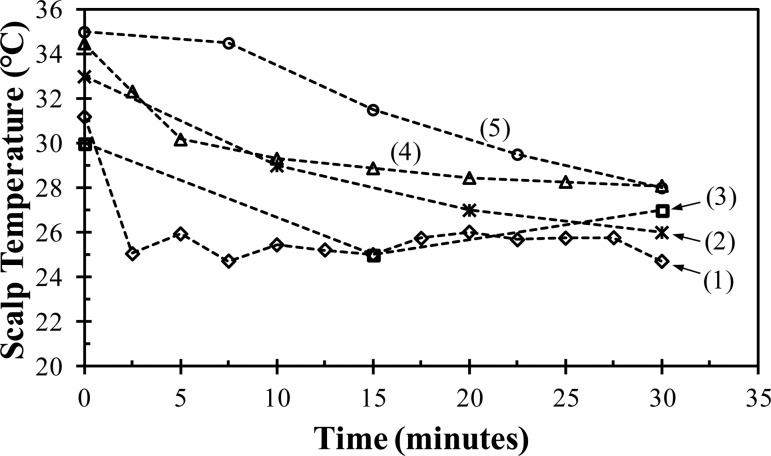
Figure 5 shows the results for the scalp temperature measurements of the healthy subject experiment. Within 5 min, the device cooled the subject's scalp to 26 °C; however, then the body thermoregulatory defenses (e.g., vasoconstriction) were triggered and temporarily prevented the scalp temperature from decreasing further. The scalp temperature varied between 25 to 26 °C during most of the experiment. Towards the end of the experiment, the body heating mechanism could not compensate for the induced hypothermia and the scalp temperatures fell below 25 °C. These results demonstrate that the device is capable of rapidly affecting the surface temperature of the head and overcoming the initial body thermoregulatory defenses.
Fig. 5.
Scalp temperature of a healthy subject as a function of time while being cooled by (1) our device as compared to (2) the average scalp temperature of six piglets cooled with a fluid circulating helmet [42], (3) the average scalp temperature of 16 patients with cardiac arrest cooled with the commercially available Frigicap® [36], (4) the average scalp temperature of 24 healthy subjects cooled by a commercially available device from Life Support Systems [40], and (5) the scalp temperature of a healthy subject cooled by a commercial device available from Paxman Coolers Ltd. [41]
Figure 5 also compares the scalp temperature measurements from our device to other scalp temperatures reported for various head cooling devices. The measurements for our device demonstrates its potential but are limited in scope and thus should be cautiously compared to the other published data, some of which represent larger sample sizes. Figure 5 includes the average scalp temperature of 24 healthy subjects cooled by a commercially available device from Life Support Systems (Mountain View, CA) [40], the scalp temperature of a healthy subject cooled by a commercially available device (Paxman Coolers Ltd., United Kingdom) [41], the average scalp temperature of 16 patients with cardiac arrest due to asystole or pulseless electrical activity who were cooled by the commercially available Frigicap® device [36], and the average scalp temperature of six piglets cooled by a fluid circulating device [42]. The final temperature of less than 25 °C after 30 min obtained from our device is the lowest of the various devices. The temperature difference of 6 °C between the scalp temperature prior to cooling (31 °C) and the temperature at the end of 30 min is comparable to other devices. However, our device achieves this difference within five minutes, as compared to 15 to 30 min for the other devices.
The final temperature and the shorter time to achieve that temperature show the potential for an improved cooling rate compared to these commercially available devices, but the question remains as to whether the cooling rate is sufficient to achieve the design goal of cooling the local brain tissue at a depth of 2.5 cm to 35 °C in 30 to 40 min.
Neglecting perfusion for the sphere cooling problem discussed in the Introduction, an effective heat transfer coefficient and Bi for the heat flow of ∼220 W was calculated for the current device. For a brain temperature of 37 °C and a cooling fluid temperature of 4 °C, the Bi was ∼15. With this Bi, mild hypothermia (35 °C) would be obtained at a radius of 4.5 cm within 10 min. Using the heat transfer rate of 80 and 122 W for the Mobile Ice and Life Support Systems devices, respectively, the corresponding Bi's were 5.5 and 8.4. With these Bi's, mild hypothermia would be obtained in the target tissue within 15 and 13 min, respectively.
Several numerical models of cooling the head have been constructed [43–47]. In the case of little to no perfusion, it has been shown that surface cooling is close to achieving the design goal [43,45]. For instance, the Life Support Systems device from Ku et al. [40] was modeled in the work of Dennis et al. [43]. In this instance, their device was able to decrease the brain temperature to 35 °C in 40 min at the required depth. Since our device has been shown to potentially have improved cooling abilities compared to the Life Support Systems device, it is expected that our device would reduce the brain temperature even further in the same time frame.
In the case of normal perfusion rates, the brain temperature is directly dependent on the arterial blood temperature [43,46]. Surface cooling is able to decrease the average exit arterial temperature by approximately 1.5 °C [43]. Thus, through the integrated neck cooling capability of our device and the expected use of cold saline infusion for TH induction, the arterial temperature should be sufficiently decreased for the device to still obtain its design goal during normal physiological perfusion. The combination of surface cooling and cold saline infusion has been shown to rapidly induce and maintain hypothermia [48].
Design Discussion
The design is focused on two key areas of optimization: identifying and minimizing the major resistance to heat transfer and determining the optimum diameter of the tubing for the cooling coils. Resistance models were used to optimize these areas and the models were validated by comparison to experimental measurements.
It is known that a major resistance to heat transfer via surface cooling is contact resistance between the patient's skin and the cooling device [31]. Efforts were made in the design to minimize the contact resistance by incorporating adjustment straps into the device which both resize the device and apply pressure to the cooling coils to force the coils into better thermal contact with the patient's head and neck. Additionally, a flexible tubing material was utilized so that the cooling coils would conform to the contours of the patient's head and neck.
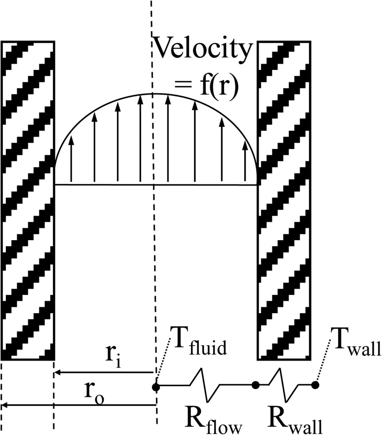
In order to determine the intrinsic heat transfer resistances of the device, the cooling coils are modeled as a 1-D resistance heat transfer problem, as shown schematically in Fig. 6, using the standard resistance equations for internal flow (see Eq. (7)) and a hollow cylinder (see Eq. (8))
Fig. 6.
Schematic of the 1-D analysis to determine the major resistance to heat flow
| (7) |
| (8) |
The flow is assumed fully developed. The thermal conductivity (k wall) of the Tygon wall is 0.34 W/m K. The tube length, outer wall temperature, and mass flow rate are assumed to be one meter, 37 °C, and 0.013 kg/s, respectively. The temperature represents the human body temperature and the mass flow rate represents the mass flow rate of the device. For turbulent flow, the Nusselt correlation, developed by Gnieliski and recommended by Holman, is used to calculate the Nusselt number [49]. For the laminar flow, a Nusselt number of 3.66 is used. A Reynolds number of 2300 is used as the transition between the turbulent and laminar flows.
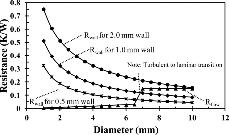
Figure 7 shows the internal convective and wall conductive resistances as a function of the inner tube diameter and tube wall thickness. The convective resistance increases linearly with increasing diameter, with a sharp increase at an inner diameter of 7 mm, which corresponds to the transition from turbulent to laminar flow. At diameters less than 7 mm, the flow is turbulent, but at diameters greater than 7 mm, in order to maintain a constant mass flow rate with the increased cross-sectional area, the velocity decreases and the flow is laminar. The wall conductive resistance exponentially decreases with the increasing tube diameter. The thicker tube wall increases the wall conductive resistance for all tube diameters. When the flow is turbulent (diameters less than 7 mm), the wall conductive resistance is an order of magnitude greater than the internal convective and is the dominant resistance to heat transfer. For instance, for an inner tube diameter of 4 mm, the convective resistance is 0.02 K/W, while the tube wall conductive resistance is 0.10 K/W and 0.32 K/W for a tube wall thickness of 0.5 mm and 2 mm, respectively. Thus, a tube thickness of 0.8 mm (the thinnest available) is used in the current design and a tube diameter and flow rate are selected to ensure a turbulent flow. A consideration for future improvement in the effectiveness of the current design would be to increase the thermal conductivity of the tubing by embedding metal powder or a metal coil into the extruded plastic.
Fig. 7.
Comparison of the internal flow resistance to the wall resistance as a function of the tube diameter. The mass flow is constant at 0.013 kg/s.
The final step for the cooling coil design is to optimize the inner diameter. The diameter optimization is accomplished by extending the 1-D model into 2-D in order to include the effects of the axially increasing fluid temperature and then determining the heat flow as a function of the tube diameter. The tube thickness is assumed to be 0.8 mm and the inlet temperature is 1 °C. The outer wall temperature, tube length, wall thermal conductivity, and mass flow rate are the same. Since neither the heat transfer rate nor the pipe outlet temperature are initially known, the use of a numerical solver with iteration is necessary in order to solve the model. The resistance model is solved by a computational platform (Mathematica®, Wolfram Research, Inc., Champaign, IL). The program iteratively solves for the outlet temperature by equating the heat transfer rates of Eqs. (6) and (9)
| (9) |
The overall heat transfer coefficient U is given by Eq. (10)
| (10) |
The heat transfer coefficient is calculated based on the flow regime and the previously cited Nusselt correlations. Once the outlet temperature is found, the heat transfer rate is calculated by Eq. (6).
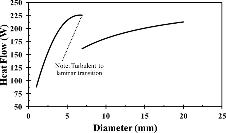
Figure 8 shows the heat transfer rate as a function of the inner tube diameter. The heat transfer increases with increasing diameter until a diameter of 5 mm, at which point the heat transfer plateaus. At an inner diameter of 7 mm, there is a discontinuity where the flow switches from turbulent (diameters less than 7 mm) to laminar (diameters greater than 7 mm). Once in the laminar region, the heat transfer rate monotonically increases with increasing diameter due to the increasing surface area with increasing diameter. There are two choices for the tube diameter: the plateau prior to the transition from turbulence to laminar flow (a diameter of 5–7 mm) or at the top end of the laminar portion of the curve (a diameter of 2 cm). A 4 mm inner diameter tube was chosen because it is near the turbulent plateau and because it ensures the flow will remain turbulent if the mass flow rate is slightly decreased (e.g., if unexpected head pressure losses were experienced in application). In addition, when wrapped in a coil, the smaller diameter can provide more points of articulation and thus should be able to form to the patient's head better than a larger diameter (e.g., 2 cm) tube wrapped into an equivalent diameter coil.
Fig. 8.
Heat flow with respect to the Tygon tube diameter for a 1 m long tube with a constant outer wall temperature of 37 °C and a mass flow rate of 0.013 kg/s
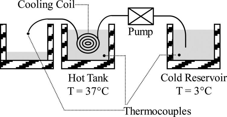
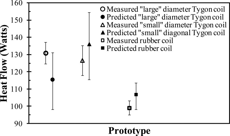
In order to validate the resistance model for the coil design, multiple coiled tubing prototypes were made: (1) a “large” diameter Tygon tube (inner diameter of 6 mm; wall thickness of 1.5 mm), (2) a “small” diameter Tygon tube (inner diameter of 4 mm; wall thickness of 0.8 mm), and (3) a silicone-rubber tube (inner diameter of 4.5 mm; wall thickness of 2 mm). As shown schematically in Fig. 9, each coil prototype was submerged in a warm water bath (37 °C), while cold water, from a reservoir of ice water (3 °C), was pumped through each coil at 0.013 kg/s. The inlet and outlet temperatures of the fluid were measured and the instantaneous heat transfer rates were determined from Eq. (6). Each prototype system was tested multiple times and their average heat transfer rates (and standard deviations represented by the error bars) were compared (see Fig. 10) to the model predictions. As can be observed, the resistance model accurately predicts the experimentally measured heat transfer rate within their respective margins of error. For example, the model predicts that for the “small” diameter Tygon coil the heat flow will be 136 ± 19 W, while the measured value is 127 ± 17 W. Note that the error bars in Fig. 10, on the predicted heat transfer rates, corresponded to a ±20% change in the calculated heat transfer coefficient. The validation of the model supports the optimization decisions (e.g., tube diameter) made during the design process.
Fig. 9.
Schematic of the hot tank experiment
Fig. 10.
Comparison of the predicted to measured heat transfer for the hot tank experiment
Conclusion
We have presented a simplified head model for predicting the initial cooling rates of different cooling methods. The predicted cooling rates for cold saline infusion (7–50 °C/h) and intravascular heat exchangers (2.5–33 °C/h) are an order of magnitude greater than for surface cooling (1.9–3.4 °C/h). Surface cooling has the advantage of easy application in prehospital settings.
We have also presented the design of a head and neck cooling apparatus. Through the initial experimentation, this device has shown a strong potential to induce mild local hypothermia in a patient's brain tissue at a depth of multiple centimeters within 30 to 40 min. The presented device has been shown to have the potential for improved heat transfer as compared to commercially available surface cooling products. When tested on a phantom head experimental apparatus, the device has a heat transfer rate of 220 W compared to 81 W for a commercial technology. In a demonstrative experiment, the device reduced the scalp temperature more rapidly than has been reported for other devices. In addition, the presented device is equipped with neck immobilization/cooling and sectional cooling capabilities for the head region. The integrated neck immobilization is for patient safety in traumatic injury cases. With integrated neck immobilization, the paramedic has minimal patient manipulation to immobilize the neck and position a cooling device. Taking advantage of the high cooling rates of cold saline infusion predicted by the model, it is expected that the device will be used in conjunction with cold saline infusion to rapidly induce hypothermia in deep brain tissue.
Future work will include a finite element analysis (FEM) of the head and neck cooling provided by the device to investigate the effect of the cooling capacity on the temperature of the brain tissue. The FEM analysis will also investigate the benefits of using cold saline infusion with the device. Further in vivo testing on multiple subjects is also needed to confirm the potential improved cooling capabilities.
Acknowledgment
The authors express their gratitude to Lucas Harder for providing exceptional technical assistance throughout this project, to Eliza W. Hartley for her assistance in preparing the manuscript, and to Char Petrowske for her assistance in fabricating the prototypes.
This study was supported in part by the Institute for Engineering and Medicine (IEM) Seed Grant Program, University of Minnesota, Minneapolis, MN.
Glossary
Nomenclature
- A =
area (m2)
- C =
specific heat (J/kg °C)
- h =
heat transfer coefficient (W/m2 °C)
- k =
thermal conductivity (W/m °C)
- L =
length (m)
- =
mass flow rate (kg/s)
- q =
heat transfer rate (W)
- Q =
volumetric flow rate (m3/s)
- q‴ =
heat generation (W/m3)
- r =
radius (m)
- R =
thermal resistance (°C/W)
- t =
time (s)
- T =
temperature (°C)
- U =
overall heat transfer coefficient (W/m2 °C)
- V =
volume (m3)
Greek Symbols
- ρ =
density (kg/m3)
- ω =
perfusion rate (ml/ml/s)
Appendix
The head is modeled as sphere with the same volume, thermal conductivity, density, and specific heat as the human brain. Each carotid artery transports, approximately, 40% of the blood flow to the brain while the vertebral arteries transport the remaining 20%. For cold saline infusion and intravascular cooling, conduction in the brain is neglected because blood perfuses the entire brain. Assuming that the cooling device utilizes one of the carotid arteries, the change in brain temperature with respect to time is given by
where the perfusion heating power q perfusion and the metabolic heating power q metabolism are
and
respectively. The perfusion rate ω and metabolic heat generation q‴ are listed in Table 1. The material properties are given in Table 3. To include the effect of perfusion in the predicted cooling rates of Table 2, T artery – T brain is assumed to be 1 °C. Initially, this term would be zero, but would increase in magnitude as the brain is cooled.
Table 3.
Thermal properties of relevant materials
The cooling power of the cold saline infusion is given by Eq. (1). The cooling power for various volumetric infusion rates Q saline are given Table 1. The saline temperature T saline and blood temperature T blood are 4 °C and 37 °C, respectively.
The cooling power of an intravascular heat exchanger is a function of the thermal resistance between the catheter and blood, the mass flow rate of the fluid in the catheter, and the temperature of the blood and catheter fluid. If the inlet T inlet and outlet T outlet temperatures are measured, the cooling power of the catheter can be calculated by Eq. (2). To calculate the cooling rates shown in Tables 1 and 2 for intravascular heat exchangers, the reported cooling power of two heat exchanger devices reported in the literature [25,26,29] are used.
To approximate the cooling rate of surface cooling, conduction cannot be ignored, but for simplicity, the effects of metabolism and perfusion are ignored. This is an obvious limitation of the model, however, the objective of the model is to determine a quick rough estimate of the initial cooling rate expected with the three different cooling methods. Initially, the brain and arterial temperatures are close and, therefore, the warming effect of the perfusion term is low. More extensive models of surface cooling can be found in the literature [36,39,41,43]. Conduction heat transfer in a sphere is
For surface cooling, a convective boundary condition is used
The solution to the problem of a sphere cooled by a convective boundary condition is found in standard texts [50,51]
where are the roots of
which are tabulated in Ref. [51]. The dimensionless temperature θ is
Here, Fo and Bi are the Fourier and Biot numbers, respectively. The initial brain temperature T brain,i and the fluid temperature T fluid are 37 and 4 °C, respectively.
Contributor Information
Adam Gladen, Department of Mechanical Engineering, , University of Minnesota, , Minneapolis, MN 55455.
Paul A. Iaizzo, Department of Surgery, , University of Minnesota, , Minneapolis, MN 55455; Department of Integrative , Biology and Physiology, , University of Minnesota, , Minneapolis, MN 55455
John C. Bischof, Department of Mechanical Engineering, , University of Minnesota, , Minneapolis, MN 55455; Department of Biomedical Engineering, , University of Minnesota, , Minneapolis, MN 55455
Arthur G. Erdman, Department of Mechanical Engineering, , University of Minnesota, , Minneapolis, MN 55455
Afshin A. Divani, Department of Mechanical Engineering, , University of Minnesota, , Minneapolis, MN 55455;; Department of Neurology, , University of Minnesota, , Minneapolis, MN 55455; Department of Neurosurgery, , University of Minnesota, , Minneapolis, MN 55455; Department of Biomedical Engineering, , University of Minnesota, , Minneapolis, MN 55455, e-mail: divani@umn.edu
References
- [1]. Krieger, D. W. , De Georgia, M. A. , Abou-Chebl, A. , Andrefsky, J. C., Sila, C. A., Katzan, I. L., Mayberg, M. R., and Furlan, A. J., 2001, “Cooling for Acute Ischemic Brain Damage (Cool Aid): An Open Pilot Study of Induced Hypothermia in Acute Ischemic Stroke,” Stroke, 32(8), pp. 1847–1854.10.1161/01.STR.32.8.1847 [DOI] [PubMed] [Google Scholar]
- [2]. Faridar, A. , Bershad, E. M. , Emiru, T. , Iaizzo, P. A. , Suarez, J. I. , Divani, A. A. , 2012, “Therapeutic Hypothermia in Stroke and Traumatic Brain Injury,” Front. Neurol., 2(80), pp. 1–11.10.3389/fneur.2011.00080 [DOI] [PMC free article] [PubMed] [Google Scholar]
- [3]. Adelson, P. D. , Ragherb, J. , Muizelaar, J. P. , Kanev, P., Brockmeyer, D., Beers, S. R., Brown, S. D., Cassidy, L. D., Chang, Y., and Levin, H., 2005, “Phase II Clinical Trial of Moderate Hypothermia After Severe Traumatic Brain Injury in Children,” Neurosurgery, 56(4), pp. 740–754.10.1227/01.NEU.0000156471.50726.26 [DOI] [PubMed] [Google Scholar]
- [4]. Arcure, J. , and Harrison, E. , 2009, “A Review of the Use of Early Hypothermia in the Treatment of Traumatic Brain Injuries,” J. Spec. Oper. Med., 9(3), p. 22. [DOI] [PubMed] [Google Scholar]
- [5]. Bernard, S. A. , and Buist, M. , 2003, “Induced Hypothermia in Critical Care Medicine: A Review,” Crit. Care Medi., 31(7), pp. 2041–2051.10.1097/01.CCM.0000069731.18472.61 [DOI] [PubMed] [Google Scholar]
- [6]. Den Hertog, H. M. , Van Der Worp, H. B. , Tseng, M. C. , and Dippel, D. W. , 2009, “Cooling Therapy for Acute Stroke,” Cochrane Database Syst Rev., 21(1), p. CD001247.10.1002/14651858.CD001247.pub2 [DOI] [PMC free article] [PubMed] [Google Scholar]
- [7]. Duz, B. , Oztas, E. , Erginay, T. , Erdogan, E. , and Gonul, E. , 2007, “The Effect of Moderate Hypothermia in Acute Ischemic Stroke on Pericyte Migration: An Ultrastructural Study,” Cryobiology 55(3), pp. 279–284.10.1016/j.cryobiol.2007.08.009 [DOI] [PubMed] [Google Scholar]
- [8]. Lyden, P. D. , Krieger, D. , Yenari, M. , and Dietrich, W. D. , 2006, “Therapeutic Hypothermia for Acute Stroke,” Int. J. Stroke, 1(1), pp. 9–19.10.1111/j.1747-4949.2005.00011.x [DOI] [PubMed] [Google Scholar]
- [9]. McIntyre, L. A. , Fergusson, D. A. , Hébert, P. C. , Moher, D. , and Hutchison, J. S. , 2003, “Prolonged Therapeutic Hypothermia After Traumatic Brain Injury in Adults,” JAMA, 289(22), p. 2992.10.1001/jama.289.22.2992 [DOI] [PubMed] [Google Scholar]
- [10]. Polderman, K. H. , van Zanten, A. R. , Nipshagen, M. D. , and Girbes, A. R. , 2004, “Induced Hypothermia in Traumatic Brain Injury: Effective if Properly Employed,” Crit. Care Med., 32(1), pp. 313–314.10.1097/01.CCM.0000104936.28288.7A [DOI] [PubMed] [Google Scholar]
- [11]. Puccio, A. M. , Fischer, M. R. , Jankowitz, B. T. , Yonas, H. , Darby, J. M. , and Okonkwo, D. O. , 2009, “Induced Normothermia Attenuates Intracranial Hypertension and Reduces Fever Burden After Severe Traumatic Brain Injury,” Neurocrit. Care, 11(1), pp. 82–87.10.1007/s12028-009-9213-0 [DOI] [PMC free article] [PubMed] [Google Scholar]
- [12]. van der Worp, H. B. , Macleod, M. R. , and Kollmar, R. , 2010, “Therapeutic Hypothermia for Acute Ischemic Stroke: Ready to Start Large Randomized Trials?,” J. Cereb. Blood Flow Metab., 30(6), pp. 1079–1093.10.1038/jcbfm.2010.44 [DOI] [PMC free article] [PubMed] [Google Scholar]
- [13]. Hemmen, T. M. , and Lyden, P. D. , 2009, “Hypothermia After Acute Ischemic Stroke,” J. Neurotrauma, 26(3), pp. 387–391.10.1089/neu.2008.0574 [DOI] [PMC free article] [PubMed] [Google Scholar]
- [14]. Kollmar, R. , Henninger, N. , Bardutzky, J. , Schellinger, P. D. , Schabitz, W. R. , and Schwab, S. , 2004, “Combination Therapy of Moderate Hypothermia and Thrombolysis in Experimental Thromboembolic Stroke—An MRI Study,” Exper. Neurol., 190(1), pp. 204–212.10.1016/j.expneurol.2004.07.006 [DOI] [PubMed] [Google Scholar]
- [15]. Gunn, A. , and Thoresen, M. , 2006, “Hypothermic Neuroprotection,” NeuroRx, 3(2), pp. 154–169.10.1016/j.nurx.2006.01.007 [DOI] [PMC free article] [PubMed] [Google Scholar]
- [16]. Hu, W.-W. , Du, Y., Li, C., Song, Y.-J., and Zhang, G.-Y., 2008, “Neuroprotection of Hypothermia Against Neuronal Death in Rat Hippocampus Through Inhibiting the Increased Assembly of GluR6-PSD95-MLK3 Signaling Module Induced by Cerebral Ischemia/Reperfusion,” Hippocampus, 18(4), pp. 386–397.10.1002/hipo.20402 [DOI] [PubMed] [Google Scholar]
- [17]. Yenari, M. , Kitagawa, K. , Lyden, P. , and Perez-Pinzon, M. , 2008, “Metabolic Downregulation: A Key to Successful Neuroprotection?,” Stroke, 39(10), pp. 2910–2917.10.1161/STROKEAHA.108.514471 [DOI] [PMC free article] [PubMed] [Google Scholar]
- [18]. Yenari, M. A. , Wijman, C. , and Steinberg, G. , 2008, “Effects of Hypothermia on Cerebral Metabolism, Blood Flow, and Autoregulation,” Therapeutic Hypothermia, Mayer S. A., and Sessler D. I., eds., Marcel Dekker, New York, pp. 141–178. [Google Scholar]
- [19]. Karibe, H. , Chen, J. , Zarow, G. J. , Graham, S. H. , and Weinstein, P. R. , 1994, “Delayed Induction of Mild Hypothermia to Reduce Infarct Volume After Temporary Middle Cerebral Artery Occlusion in Rats,” J. Neurosurg., 80(1), pp. 112–119.10.3171/jns.1994.80.1.0112 [DOI] [PubMed] [Google Scholar]
- [20]. Xue, D. , and Huang, Z. , 1992, “Immediate or Delayed Mild Hypothermia Prevents Focal Cerebral Infarction,” Brain Res., 587(1), pp. 66–72.10.1016/0006-8993(92)91428-H [DOI] [PubMed] [Google Scholar]
- [21]. Parent, A. , and Carpenter, M. B. , 1996, Carpenter's Human Neuroanatomy, Williams and Wilkins, Baltimore. [Google Scholar]
- [22]. Xu, X. , Tikuisis, P. , and Giesbrecht, G. , 1999, “A Mathematical Model for Human Brain Cooling During Cold-Water Near-Drowning,” J. Appl. Physiol., 86(1), pp. 265–272. [DOI] [PubMed] [Google Scholar]
- [23]. Shitzer, A. , and Eberhart, R. C. , 1985, Heat Transfer in Medicine and Biology, Springer, New York, pp. 312–320. [Google Scholar]
- [24]. Konstas, A. A. , Neimark, M. A. , Laine, A. F. , and Pile-Spellman, J. , 2007, “A Theoretical Model of Selective Cooling Using Intracarotid Cold Saline Infusion in the Human Brain,” J. Appl. Physiol., 102(4), pp. 1329–1340.10.1152/japplphysiol.00805.2006 [DOI] [PubMed] [Google Scholar]
- [25]. Wang, Y. , and Zhu, L. , 2007, “Targeted Brain Hypothermia Induced by an Interstitial Cooling Device in Human Neck: Theoretical Analyses,” Eur. J. Appl. Physiol., 101(1), pp. 31–40.10.1007/s00421-007-0451-6 [DOI] [PubMed] [Google Scholar]
- [26]. Dae, M. W. , Gao, D. W. , Ursell, P. C. , Stillson, C. A. , and Sessler, D. I. , 2003, “Safety and Efficacy of Endovascular Cooling and Rewarming for Induction and Reversal of Hypothermia in Human-Sized Pigs,” Stroke, 34(3), pp. 734–738.10.1161/01.STR.0000057461.56040.FE [DOI] [PubMed] [Google Scholar]
- [27]. Luan, X. , Li, J. , McAllister, J. P. II, Diaz, F. G., Clark, J. C., Fessler, R. D., and Ding, Y., 2004, “Regional Brain Cooling Induced by Vascular Saline Infusion Into Ischemic Territory Reduces Brain Inflammation in Stroke,” Acta Neuropathol. (Berl), 107(3), pp. 227–234.10.1007/s00401-003-0802-2 [DOI] [PubMed] [Google Scholar]
- [28]. Holzer, M. , Behringer, W. , Janata, A. , Bayegan, K., Schima, H., Deckert, Z., Losert, U., Laggner, A. N., and Sterz, F., 2005, “Extracorporeal Venovenous Cooling for Induction of Mild Hypothermia in Human-Sized Swine,” Crit. Care Med., 33(6), pp. 1346–1350.10.1097/01.CCM.0000166356.45902.A2 [DOI] [PubMed] [Google Scholar]
- [29]. Georgiadis, D. , Schwarz, S. , Kollmar, R. , and Schwab, S. , 2001, “Endovascular Cooling for Moderate Hypothermia in Patients With Acute Stroke: First Results of a Novel Approach,” Stroke, 32(11), pp. 2550–2553.10.1161/hs1101.097382 [DOI] [PubMed] [Google Scholar]
- [30]. Pichon, N. , Amiel, J. B. , Francois, B. , Dugard, A. , Etchecopar, C. , and Vignon, P. , 2007, “Efficacy of and Tolerance to Mild Induced Hypothermia After Out-of-Hospital Cardiac Arrest Using an Endovascular Cooling System,” Crit. Care, 11(3), p. R71.10.1186/cc5956 [DOI] [PMC free article] [PubMed] [Google Scholar]
- [31]. Diller, K. R. , and Zhu, L. , 2009, “Hypothermia Therapy for Brain Injury,” Annu. Rev. Biomed. Eng., 11, pp. 135–162.10.1146/annurev-bioeng-061008-124908 [DOI] [PubMed] [Google Scholar]
- [32]. Lampe, J. W. , and Becker, L. B. 2007, “Rapid Cooling for Saving Lives: A Bioengineering Opportunity,” Exp. Rev. Med. Devices, 4(4), pp. 441–446.10.1586/17434440.4.4.441 [DOI] [PubMed] [Google Scholar]
- [33]. Wang, H. , Olivero, W. , Lanzino, G. , Elkins, W., Rose, J., Honings, D., Rodde, M., Burnham, J., and Wang, D., 2004, “Rapid and Selective Cerebral Hypothermia Achieved Using a Cooling Helmet,” J. Neurosurg., 100(2), pp. 272–277.10.3171/jns.2004.100.2.0272 [DOI] [PubMed] [Google Scholar]
- [34]. Qiu, W. , Shen, H. , Zhang, Y. , Wang, W., Liu, W., Jiang, Q., Luo, M., and Manou, M., 2006, “Noninvasive Selective Brain Cooling by Head and Neck Cooling is Protective in Severe Traumatic Brain Injury,” J. Clin. Neurosci.: Neurosurg. Soc. Australas., 13(10), pp. 995–1000.10.1016/j.jocn.2006.02.027 [DOI] [PubMed] [Google Scholar]
- [35]. Liu, W. G. , Qiu, W. S. , Zhang, Y. , Wang, W. M. , Lu, F. , and Yang, X. F. , 2006, “Effects of Selective Brain Cooling in Patients With Severe Traumatic Brain Injury: A Preliminary Study,” J. Int. Med. Res., 34(1), pp. 58–64.10.1177/147323000603400107 [DOI] [PubMed] [Google Scholar]
- [36]. Hachimi-Idrissi, S. , Corne, L. , Ebinger, G. , Michotte, Y. , and Huyghens, L. , 2001, “Mild Hypothermia Induced by a Helmet Device: A Clinical Feasibility Study,” Resuscitation, 51(3), pp. 275–281.10.1016/S0300-9572(01)00412-9 [DOI] [PubMed] [Google Scholar]
- [37]. Polderman, K. H. , and Herold, I. , 2009, “Therapeutic Hypothermia and Controlled Normothermia in the Intensive Care Unit: Practical Considerations, Side Effects, and Cooling Methods,” Crit. Care Med., 37(3), pp. 1101–1120.10.1097/CCM.0b013e3181962ad5 [DOI] [PubMed] [Google Scholar]
- [38]. Holzer, M. , 2008, “Devices for Rapid Induction of Hypothermia,” Eur. J. Anaesthesiol. Suppl., 42, pp. 31–38.10.1017/S0265021507003274 [DOI] [PubMed] [Google Scholar]
- [39]. McKean, S. , 2009, “Induced Moderate Hypothermia After Cardiac Arrest,” AACN Adv. Crit. Care, 20(4), pp. 342–353.10.1097/NCI.0b013e3181bcea4e [DOI] [PubMed] [Google Scholar]
- [40]. Ku, Y. T. , Montgomery, L. D. , Webbon, B. W. , 1996, “Hemodynamic And Thermal Responses to Head and Neck Cooling in Men and Women,” Am. J. Phys. Med. Rehabil., 75(6), pp. 443–450.10.1097/00002060-199611000-00008 [DOI] [PubMed] [Google Scholar]
- [41]. Janssen, F. P. , Rajan, V. , Steenbergen, W. , van Leeuwen, G. M. , and van Steenhoven, A. A. , 2007, “The Relationship Between Local Scalp Skin Temperature and Cutaneous Perfusion During Scalp Cooling,” Physiol. Meas., 28(8), pp. 829–839.10.1088/0967-3334/28/8/006 [DOI] [PubMed] [Google Scholar]
- [42]. Laptook, A. R. , Shalak, L. , and Corbett, R. J. , 2001, “Differences in Brain Temperature and Cerebral Blood Flow During Selective Head Versus Whole-Body Cooling,” Pediatrics, 108(5), pp. 1103–1110.10.1542/peds.108.5.1103 [DOI] [PubMed] [Google Scholar]
- [43]. Dennis, B. H. , Eberhart, R. C. , Dulikravich, G. S. , and Radons, S. W. , 2003, “Finite-Element Simulation of Cooling of Realistic 3-D Human Head and Neck,” ASME J. Biomech. Eng., 125(6), pp. 832–840.10.1115/1.1634991 [DOI] [PubMed] [Google Scholar]
- [44]. Diao, C. , Zhu, L. , and Wang, H. , 2003, “Cooling and Rewarming for Brain Ischemia or Injury: Theoretical Analysis,” Ann. Biomed. Eng., 31(3), pp. 346–353.10.1114/1.1554924 [DOI] [PubMed] [Google Scholar]
- [45]. Janssen, F. E. , van Leeuwen, G. M. , and van Steenhoven, A. A. , 2005, “Modelling of Temperature and Perfusion During Scalp Cooling,” Phys. Med. Biol. 50(17), pp. 4065–4073.10.1088/0031-9155/50/17/010 [DOI] [PubMed] [Google Scholar]
- [46]. Nelson, D. A. , and Nunneley, S. A. , 1998, “Brain Temperature and Limits on Transcranial Cooling in Humans: Quantitative Modeling Results,” Eur. J. Appl. Physiol., 78(4), pp. 353–359.10.1007/s004210050431 [DOI] [PubMed] [Google Scholar]
- [47]. Zhu, L. , and Rosengart, A. J. , 2008, “Cooling Penetration Into Normal and Injured Brain Via Intraparenchymal Brain Cooling Probe: Theoretical Analyses,” Heat Transfer Eng., 29(3), pp. 284–294.10.1080/01457630701758062 [Google Scholar]
- [48]. Neimark, M. A. , Konstas, A. A. , Choi, J. H. , Laine, A. F. , and Pile-Spellman, J. , 2008, “Brain Cooling Maintenance With Cooling Cap Following Induction With Intracarotid Cold Saline Infusion: A Quantitative Model,” J. Theor. Biol., 253(2), pp. 333–344.10.1016/j.jtbi.2008.03.025 [DOI] [PubMed] [Google Scholar]
- [49]. Holman, J. P. , 2001, Heat Transfer, McGraw-Hill, New York. [Google Scholar]
- [50]. Bergman, T. L. , Lavine, A. S. , Dewitt, D. P. , and Incropera, F. P. , 2011, Introduction to Heat Transfer, John Wiley and Sons, Hoboken, NJ, pp. 298–310. [Google Scholar]
- [51]. Schneider, P. J. , 1957, Conduction of Heat Transfer, Addison-Wesley, Cambridge, MA, pp. 250–265. [Google Scholar]


