Abstract
Background
The robot-assisted minimally-invasive surgery is well recognized as a feasible solution for diagnosis and treatment of the prostate cancer in human.
Methods
In this paper the kinematics of a parallel 4 Degrees-of-Freedom (DOF) surgical manipulator designed for minimally invasive in-bore prostate percutaneous interventions through the patient's perineum. The proposed manipulator takes advantage of 4 sliders actuated by MRI-compatible piezoelectric motors and incremental rotary encoders. Errors, mostly originating from the design and manufacturing process, need to be identified and reduced before the robot is deployed in the clinical trials.
Results
The manipulator has undergone several experiments to evaluate the repeatability and accuracy of the needle placement which is an essential concern in percutaneous prostate interventions.
Conclusion
The acquired results endorse the sustainability, precision (about 1 mm in air (in x or y direction) at the needle's reference point) and reliability of the manipulator.
Keywords: Prostate transperineal intervention, parallel manipulator, MRI compatible, calibration assessment, biopsy
Introduction
Prostate cancer is ranked the second cause of cancer death among all the cancer categories, and the most common cancer in men in the United States, according to the American Cancer Society report [1].
Needle-based percutaneous interventions, including biopsy, which is the gold standard for diagnosis, and brachytherapy, as a common treatment, are typical diagnostic and therapeutic approaches for prostate cancer. In those interventions, needles are often guided into pre-defined regions in the prostate gland guided by transrectal ultrasound (TRUS) [2-4]. More recently, magnetic resonance imaging (MRI) has been investigated as an alternative to TRUS to guide prostate interventions [5-9]. Because MRI offers high-resolution volumetric images with superior soft tissue contrast, it offers better delineation of foci, hence assisting accurate image-guided targeting.
The MRI's capability to guide accurate tumor targeting could be further enhanced by robotic assistance. Robot-assisted interventional procedures afford significant advantages over manual approaches in terms of precision, repeatability, reliability, as well as ergonomics. However, the high magnetic field, potential electrical interference, and limited access of closed-bore MRI scanner render significant challenges to developing robotic system that can perform percutaneous interventions under live MRI-guidance.
MRI-guided robotic systems for prostate percutaneous interventions have been investigated with considerable efforts during the last decade. In the perspective of mechanism design, all components have to be constructed with non-ferrous and non-magnetic materials. The robot is designed to be used in the bore of the scanner in the intended configuration, and it could be classified as MR-conditional under the ATSM 2503-13 standard. The robot should be compact enough to fit into the tightly constrained closed-bore MRI scanner, as well as providing effective workspace. With respect to (w.r.t.) the actuation methods, currently existing robotic systems can be mainly categorized as manually, pneumatically, and piezoelectrically actuated systems. Krieger et al. designed a 2-DOF passive and manual manipulator to perform transrectal prostate biopsy under MRI-guidance [10]. Fischer et al. presented a pneumatically actuated robotic system for transperineal prostate interventions with 2 actuated DOFs and manual needle insertion [11]. It is further improved by Song et al. [12], replacing the 2-DOF Cartesian stage with 4-DOF parallel platform offering needle angulation. Patriciu et al. designed an automatic brachytherapy seeds placement robotic system with pneumatic actuators [13]. A 4-DOF surgical robot is conceptually designed for MRI-guided prostate interventions and neurosurgery approaches [14]. A fully actuated robotic-assisted system is developed for prostate biopsy and brachytherapy as well as delivering concentric-tube continuum robot employing piezoelectric actuator, which comprises of 3-DOF Cartesian stage and 3-DOF needle driver module [15, 16]. Goldenberg et al. reported a robotic system for transperineal prostate intervention with ultrasound actuators [17]. Tadakuma et al. presented an MRI-guided robot for transperineal needle placement based on dielectric elastomer actuators [18].
For those patients with previous colectomy, the transrectal prostate biopsy using ultrasound probe could not be feasible; therefore, we developed a surgical manipulator for the transperineal percutaneous interventions. In our previous effort, a proof of concept of an in-bore 4-DOF parallel surgical manipulator for percutaneous perineum prostate biopsy and brachytherapy planning was proposed. Such system is composed of two trapezoid-shaped linkages [19], replacing the original triangle-shape stages and the spherical joint embedded in the front stage for more accurate needle placement [12, 20]. Because of different sources of inaccuracies including manufacturing, operation of limit switches, robot controller and kinematic parameters, it is required to discover error quantities, and hence, reduce and possibly eliminate them. Hence, it is crucial for a manufactured system to undergo a comprehensive calibration test before being deployed for the clinical trials [21-24].
In this paper, an MRI assisted modular surgical manipulator is introduced for the purpose of minimally invasive transperineal percutaneous prostate (biopsy/brachytherapy) interventions. This robot is targeted for manual needle insertion into the tissue and has undergone modifications for improved precision and ergonomic compatibility. Due to the MRI compatibility constraint in the design procedure, most parts of the robot are made by the plastic materials (CNC machined high strength Polycarbonate (20% glass filled), 3D printed ULTEM 9085, ULTEM 1000, 3D printed Acrylonitrile Butadiene Styrene (ABS), Cast Nylon, …) resulting in a somewhat compliant mechanism that may deform under different conditions (e.g., pressure, long-term operation, …). Since this robot is aimed to get the institutional review board (IRB) approval, it is necessary to evaluate its accuracy and repeatability for the clinical trials. A kinematic study of the modular manipulator is thus carried out to specify each slider position in order to manipulate the robot for reaching different targets within the workspace. A series of accuracy and repeatability assessment tests are quantitatively established to evaluate the system's overall consistency and reliability. In addition to the robot precision study, an analysis of the compatibility of the robot in the MR imaging environment is performed for different situations and the signal-to-noise ratio (SNR) results are correspondingly reported.
Materials and Methods
The 4-DOF parallel manipulator presented in this study (Fig. 1) is composed of two similar front and rear trapezoid stages (each stage is made by a parallelogram mechanism [19] allowing motion in the vertical plane). This system combines the motion of four linear sliders (driven by a customized lead-screw table with 2 mm pitch generating motion in the horizontal plane) to provide 2-DOF Cartesian and 2-DOF angulation motions of the needle driver. Due to obstacles which may block the path of the needle for the direct insertion (e.g. urethra, pubic arc, bladder, blood vessels and bones), the robot enables the clinician by his/her intuition to decide if the needle needs angulation and if so decide how the most appropriate angled needle path. In such case, the manipulator should make a particular configuration to facilitate the needle angulation by setting different positions of the front and rear trapezoid stages. There are customized fiber optic limit switches mounted on both ends of each slider, used as the safety stop to prevent the slider from hitting the lateral supports and being damaged. In addition, the actuation system takes advantages of a belt drive transmission system and anti-backlash nuts with tight tolerances to eliminate the undesired play during the motion.
Figure 1.
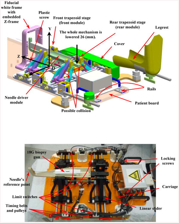
Parallel manipulator prototype: conceptual design (top) and current implementation without the protection cover (bottom).
Figure 1 represents the conceptual design (CAD model) (top) and the current implementation of the manipulator prototype (bottom). The cover, shown in the CAD model representatively on one side, protects the motors and mechanical transmissions for safely run in the clinical procedure. The robot is integrated into a platform equipped with four carriages which slides into two rails embedded in the patient board (Fig.1, top) and is locked in place by tightening two locking screws (brass socket head cap screws size UNC ¼”-20 with plastic thumb knobs, Fig.1 bottom). The patient is placed inside the scanner and his legs are secured and fixed by two leg supports. The fiducial frame is placed next to the patient's perineum and is secured by a plastic screw. A z-frame calibration device is aimed for this purpose having nine embedded fiducial gadolinium markers casting as the contrast agent for automatic registration (Fig. 1). The idea of using z-frame to register the scanner and robot coordinates was initially proposed in [25]. With the robot and patient positioned, the clinician takes MR images of the prostate gland and registration fiducial, and determines where the needle should be deployed inside the tissue. The robot moves accordingly until it places the needle guide in a configuration ready for the needle insertion and biopsy. During the design and manufacturing procedures of the robot we expect the desired accuracy of the robot be maintained within 1 mm at the needle's reference point (Fig. 1-bottom) and about 2-3 mm inside the tissue. These numbers are referred to either in x or y direction (in a 2D plane) so that remaining within this range could be assessed as the accuracy of the robot.
The current prototype of the manipulator has undergone a series of modifications compared to the previous version [19] to resolve the manipulator-patient's leg interference. This has been done through lowering the height of the front and rear stages about 26 mm (Fig. 1) still preserving the same workspace to avoid any further collision.
After specifying the correlation between the needle's tip and the target in the MR image by using the transformation matrices, the kinematics equations described in Section III provide the corresponding positions for sliders to manipulate the robot accordingly.
Kinematic Analysis
The following describes the kinematic analysis of the robot.
A. Forward kinematics
The origin of the robot's coordinate system is located at the bottom-center of the front stage as shown in Fig. 1. This coordinate is further utilized for registering the needle's tip to the MR scanner coordinates by passing through the z-frame registration coordinate. The needle's tip position and orientation are set by the 2-DOF motion in the X-Y plane of each of the two trapezoid stages (Pf and Pr). Equation (1) represents the relationship between the needle's tip coordinate and the origin of the front stage.
| (1) |
where h is the distance between the needle's direction and the center of the front trapezoid stage in the vertical direction (i.e., ĵ), X⃗n, Y⃗n, Z⃗n represent the position of the needle's tip, X⃗p, Y⃗p, Z⃗p correspond to the position of the point of rotation while Z⃗p = 0 here, L = 185 mm is the needle's reference plane and the point of rotation along the Z-direction (constant) and L1 is the insertion depth by inserting the biopsy gun into the tissue (variable and determined by the clinician depending on the position of the target along the Z-direction) (Figs. 2, 4).
Figure 2.
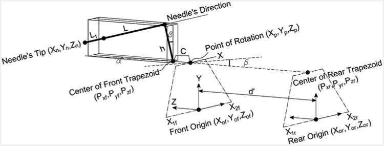
Kinematic diagram of the manipulator to correlate the movement of sliders to the needle's tip motion.
Figure 4.
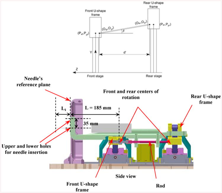
Front and rear stages and the centers of rotation for each corresponding stage (Oxf, Oyf ) and (Oxr, Oyr ).
Note that β is in the Y-Z plane and α in the X-Z plane. There is a main point that we call it the “point of rotation” which the needle driver rotates around it (shown in Fig. 2). The position of that point can be given as:
| (2) |
where, C is the distance between the point of rotation and center of the front trapezoid stage in the Z-direction, P⃗xf, P⃗yf are the coordinates of the mid-point of the U-shape in the front stage and are aligned with the point of the rotation in the horizontal direction (Fig. 2).
Equation (3) correlates P⃗xf, P⃗yf to the positions of 2 front sliders along the X-axis (x1f,x2f):
| (3) |
Figure 3 displays the vertical range of the stage motion (or “y” that corresponds to the lower hole designated for the needle insertion as shown in Fig. 4) which is confined between 90 mm < y < 157 mm (noting that the home position is determined at 125 mm in the vertical direction). This figure also shows the values for h1,h2, a1,b. Similarly, for the rear stage it can be described as:
Figure 3.
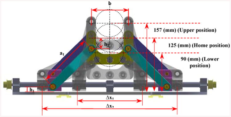
Front trapezoid stage (frontal planar view): a1 = 124 mm, b = 84 mm, h1 = 12 mm, h2 = 25 mm.
| (4) |
where x1r,x2r are the positions of the 2 rear sliders along the X-axis. By having the values of x1f,x2f,x1r,x2r, the position and orientation of the needle's tip can be calculated from Eqs. (1)-(4). Hence, two dependent variables α, β (Figs. 2, 4) can be computed as:
| (5) |
| (6) |
The effective distance ( d′ ) between the front and rear centers of rotation is shown in Fig. 4 (Noting that the front center of rotation is identical to the point of rotation defined earlier).
B. Inverse kinematics
Once the position of the tumor is determined by the clinician through the RadVision™ environment, he/she decides to deploy the needle into the tissue. In such case, the set point positions of four sliders are calculated in order to have the controller send commands to each joint. This would manipulate the robot to take a specific posture and make the needle in a direction ready for the insertion. The following inverse kinematic equations are required to finding the prismatic joints' positions:
| (7) |
| (8) |
| (9) |
By substituting x2f from (7) into (9); it yields:
| (10) |
and similar for the rear stage:
| (11) |
C. Motion's Constraints of the Manipulator
In some configurations the needle driver may collide with the U-shape frame or middle supports (Fig. 1) when elevating or lowering and possibly being damaged. In order to avoid such situations, we propose some motion's constraints. The relative distance between the front and rear stages creating two introduced angles α and β always kept at some values less than 10° (in order to avoid the collision between the needle driver and the front stage) which is established in the protocol of the robot's requirements. Given this fact, we find the relevant constraints on each slider in order to be taken into account by the controller.
Constraints:
| (12) |
| (13) |
The 1st constraint can be concluded as:
1st constraint:
| (14) |
| (15) |
| (16) |
| (17) |
After simplification, the 2nd constraint can be found as:
2nd Constraint:
| (18) |
Another constraint on the manipulator's motion is the upper and lower limits when the robot reaches to the close vicinity of the lateral and middle supports. These types of constraints could be related to the position of 4 sliders as follows (as shown in Fig. 3):
| (19) |
Where Δx1 =119.74 mm and Δx2 =269.14 mm.
D. Analytical Workspace
The tip position and orientation of the needle can be determined by the clinician based on the position of the prostate gland. This task is performed via the RadVision™ software incorporating with the MRI scanner software by having which [x, y, z] denoting the needle's tip position and [u, v, w] representing the needle's orientation RAS coordinates (Right-Anterior-Superior patient coordinates). This target is sent to the robot controller software through the navigation program.
Figure 5 displays the 2D and 3D workspace of the manipulator. In order to account for patient variability, two insertion guiding holes are incorporated into the needle driver in order to expand the workspace 1 (WS 1) to workspace 2 (WS 2) (Fig. 4). Therefore, using the upper hole can vertically shift the workspace 35 mm higher (Figs. 4, 5).
Figure 5.
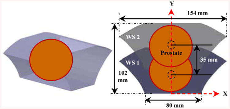
3D (left) and 2D (right) analytical robot workspace.
Different coordinates systems are defined as , , , indicate the serial chain of transformation from the scanner frame to the z-frame, then z-frame to robot, robot to needle's tip to provide the direct transformation from the scanner to the needle's tip, respectively as follows (Fig. 7):
Figure 7.
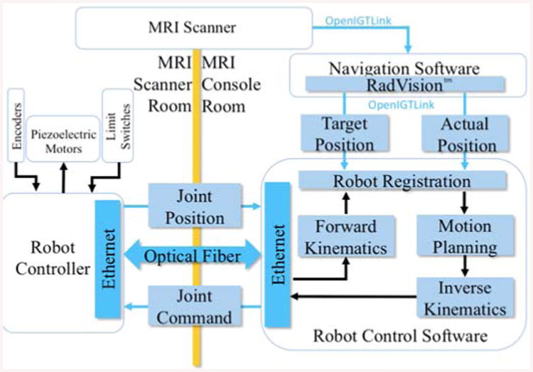
Architecture diagram of the actuation system.
| (20) |
| (21) |
Robot Actuation Principle and Control Architecture
The manipulator takes advantage of a non-magnetic ultrasonic double shaft motor (USR60-S4N, Shinsei Corp., Tokyo, Japan) which is able to provide maximum 1 (N.m) torque and recommended speed of 100 (rpm), at each slider. There is a rotary incremental quadrature encoder (resolution of 5,000 counts/rev, US Digital, Vancouver, Washington) supplied with the piezoelectric motor providing position feedback. Encoders are directly attached to the motor shafts, measuring the motor shaft rotation. Belt drive transmission and anti-backlash nuts are used to eliminate the undesired play during the motion. Four ultrasonic motors are controlled by the customized MRI-compatible robot controller [26, 27], providing high precision closed-loop control.
Figure 7 represents a diagram of the actuation system where the communication between the robot controller's software and RadVision™ is through the OpenIGTLink protocol [32]. After the task space (i.e. patient/image coordinates) target position is sent from RadVision™ through OpenIGTLink, the forward and inverse kinematics calculation is done in the robot control software. The calculated joint space target position is sent to the robot controller communicating through an optical fiber which is inside the MRI scanner room. Encoders, piezoelectric motors, and limit sensors interface with the robot controller and its piezoelectric motor drivers.
The robot is actuated by a customized controller residing in the MRI room during the operation. The wiring for the sensors and actuators is carried out through radio frequency (RF) shielded cables prepared for this purpose. The controller consists of four customized piezoelectric motor driver boards to perform low level control task as well as produce the control signal for actuating the motors [26].
The piezoelectric motor driver board is constructed with a high speed FPGA-based control signal generator [27]. Figure 8 illustrates the actuation principle of the controller's components. In order to get reliable signals, the encoders and limit switches have differential outputs. Their signal is first processed by low-voltage differential signaling (LVDS) driver attached to the sensor and then the LVDS receiver on each driver board inside the controller box. After the encoder data is received by FPGA (Cyclone EP2C8Q208C8, Altera Corp.), a microcontroller (PIC32MX460F512L, Microchip Tech.) is in charge of the joint level control while the calculation of forward and inverse kinematics is done in the robot control application. The motor control signal is then generated and processed by FPGA, digital-to-analog converter (DAC) and linear amplifier (AMP) to the Shinsei driver (D6060, Shinsei Corp., Tokyo, Japan). Finally the motor driving signal is transmitted out of the controller by the RF shielded cable.
Figure 8.
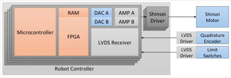
Actuation functionality diagram.
Eights fiber optic limit switches including LED and photodiode are designated to detect the sliders before touching the lateral supports. Figures 1 and 9 show the layout of the 8 limit switches in such a way they would not block the pathway of the moving sliders during their operation. These sensors are used both for safety as well as initialization of the robot position.
Figure 9.
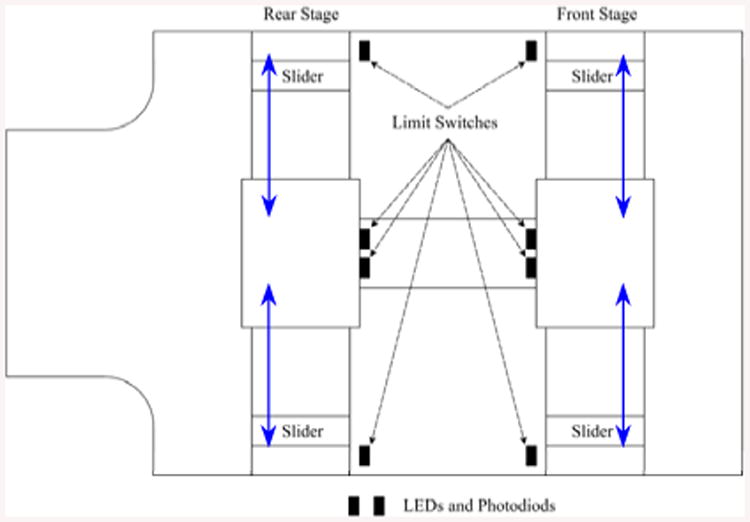
LEDs and photodiodes layout on the robot base.
Results and Discussion
A. Tasks and Experimental Setup
A primary contribution of this work is to assess the robot's repeatability and accuracy, and hence, consider how different sources of errors could influence the final objective which is placing the needle into the tissue. To this, we performed this validation in the following three tasks:
Checking individual slider's backlash and positioning accuracy and ensuring it is in an acceptable range. Also performing the probe pivot calibration.
Accuracy and repeatability tests with needle translation (no angulation).
Repeatability test with needle angulation (i.e., positioning the needle in an angle w.r.t. the home position in X- and Y-directions).
Accuracy is defined as the Euclidean distance between a measured position and the desired target position (for instance, the needle's tip position). Repeatability is the range of variations under identical situations when the system is sent to the same position or the standard deviation of a cloud of data [23, 29-31].
B. Backlash Evaluation and Pivot Calibration
Each slider is equipped with an anti-backlash nut to eliminate unnecessary small motions; however, reducing the backlash increases the friction, and hence, results in wearing of the joints. In this case, it is critical to consider inaccuracies in each prismatic joint under a repeatable task and to define an acceptable range for backlash (i.e., based on our previous experience the acceptable range is to set a value less than 0.1 mm, or equivalent to 10% from the desired robot's accuracy in air (i.e., 1 mm)). For this purpose by jogging each motor we manually place the robot at the home position (i.e., (X,Y)=(0,125)) by using a designated spacer to ensure the equivalent distance for each slider from its corresponding side. For this experimental setup we use two different measuring apparatuses: a 3-digit dial indicator (3 um accuracy) and the Optotrak 3020 navigation system (Northern Digital Inc.). Optotrak 3020 is widely used due to its high accuracy (RMS accuracy at 2.25 m distance is 0.1mm for X, Y coordinates and 0.15 mm for Z coordinate according to the manufacturer catalogue) at maximum marker rate 3,500 Hz (assuming 3 markers). The Optotrak-to-robot distance has a direct influence on the accuracy of the camera and measurement reliability. The recommended minimum and maximum distance is 1.48 < x < 5.30 m [21].
We did a quantitative study on the backlash and joint level accuracy of the moving components. To this aim, we used the dial indicator by placing it in contact with each slider of the robot to measure the range of inaccuracy in a back-and-forth movement (Fig 10). Starting from an arbitrary position (set the dial indicator to zero at this point) we then commanded the corresponding motor of each slider to move to a value of 2 mm increment and 6 mm overall travel (i.e., 3 steps with 2 mm increment) and repeated the same scenario but in the opposite direction until reaching the original set point. This procedure was tested four times for the four sliders to assess the amount of backlash. We read the offset error on the indicator corresponding to backlash and other inaccuracies in the system. The maximum backlashes were approximated as 86, 10, 87, and 65 μm for the Front Right, Front Left, Rear Right, and Rear Left (FR, FL, RR, and RL) sliders, respectively. It should be noted that in the first evaluation test, we noticed the backlash values were relatively higher than 0.1 mm and far away from our initial expectation; therefore, we tuned the anti-backlash nuts and repeated the experiment so that the current numbers represent the corresponding values after the adjustment.
Figure 10.
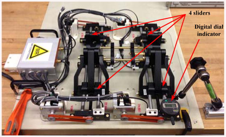
Testing backlash for each individual slider with a 3-digit dial indicator.
According to Ref. [21], the Optotrak accuracy is about 0.1 mm if the distance between the sensors and the markers are about 2.25 m. For this reason, we placed the robot at a similar distance (e.g., 2.4 m) in which all tracker sensors were able to detect the markers. Figure 11 shows the experimental setup including a 6-marker reference rigid body fixed to the robot base and a 6-marker probe connected to the needle guide. A standard pivot calibration, based on the tracking system user's manual was performed. Similar with the procedure used in [24] we pivoted the Optotrak pointer in a small dimple precisely machined on the robot base and collected a large number of readings that we averaged out to obtain the position of the tool tip. Analyzing data turned out the maximum standard deviation for a similar pivot after repeating three times was about 0.036 mm revealing the high accuracy of the Optotrak system.
Figure 11.
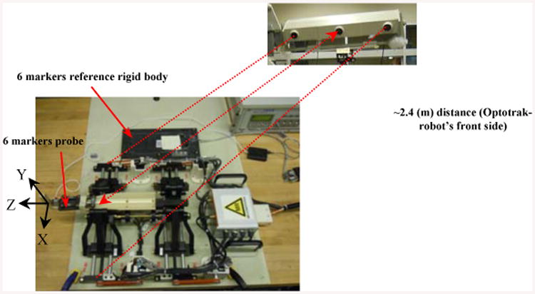
Experimental setup with the reference rigid body and the Optotrak system.
C. Accuracy and Repeatability Test
There are a number of factors involved in the overall accuracy of a robotic system such as dynamics, structure, and kinematics [23] that could be mostly compensated for inaccurate errors. Having such an insight in the process of design and manufacturing, it is compulsory to assess the accuracy and confirm its uniformity for the entire workspace before moving forward for the clinical procedures. Hence, in this study, a probabilistic experiment on the robot calibration was carried out to ensure the capability of the robot in approaching different targets within the workspace by having an acceptable but minimum range of error (the experimental setup is shown in Fig. 11).
a) Straight Insertion
First we assessed the accuracy of straight needle insertions, i.e. needles aligned with the Z-axis of the robot. Starting from the home position and reaching different targets could determine the extent of repeatability and precision of the robot for all sessions. For this reason we calculated the relative distance between each target and the home position in every session (Ti-Home). Table I depicts the average values of the experimental data collected for 13 quantified targets as a result of 8 sessions for the first 9 targets and an expanded set of 25 sessions for the additional 4 targets. “Ti” corresponds to the relevant target position and “H” denotes the home position. It should be pointed that the manipulator is manually placed at the home position before initiating each session. The cloud data represents an acceptable repeatability with a maximum deviation (error) about 0.28 mm in X and 0.21 mm in the Y-direction In addition, the system possesses accuracy about 0.73 mm in the X and 0.28 mm in the Y-direction as shown in the |Δx|, |Δy| column. The overall repeatability average (i.e., average of the STDEV (X,Y) column in Table I) is 0.09 mm in X and 0.13 mm in Y–direction. It should be noted that the X and Y values in Table I are represented with respect to the reference rigid body shown in Fig. 11 indicating the accuracy in the X-Y plane.
Table I.
Accuracy and Repeatability Test – 13 Targets with 12 Relative Distances (Ti - Home) – 8 and 25 Sessions – all measurements are in mm.
| Tj-Home | AVE(X,Y)measured | (X,Y)commanded | (|ΔX|,|ΔY|) | STDEV (X\Y) |
|---|---|---|---|---|
| T2-H(8) | (24.76, 0.02) | (25, 0) | (0.24, 0.02) | (0.09, 0.18) |
| T3-H (8) | (24.77, -24,72) | (25, -25) | (0.23, 0.28) | (0.09, 0.21) |
| T4-H (8) | (-0.09, -24,97) | (0, -25) | (0.09, 0.03) | (0.28, 0.12) |
| T5-H (8) | (-25.22,-25.06) | (-25, -25) | (0.22, 0.06) | (0.01, 0.15) |
| T6-H (8) | (-25.14,-0.09) | (-25, 0) | (0.14, 0.09) | (0.03, 0.16) |
| T7-H (8) | (-24.38, 24.82) | (-25, 25) | (0.62, 0.18) | (0.25, 0.04) |
| T8-H (8) | (0.68, 24.78) | (0, 25) | (0.68, 0.22) | (0.17, 0.13) |
| T9-H (8) | (25.73, 24.84) | (25, 25) | (0.73, 0.16) | (0.02, 0.12) |
| T10-H (25) | (20.47, 24.81) | (20, 25) | (0.47, 0.19) | (0.05, 0.14) |
| T11-H (25) | (14.73, -19.69) | (15, -20) | (0.27, 0.31) | (0.01, 0.16) |
| T12-H (25) | (-5.26, -4-94) | (-5, -5) | (0.26, 0.06) | (0.02, 0.07) |
| T13-H (25) | (-9.93, 14.83) | (-10, 15) | (0.07, 0.17) | (0.03, 0.08) |
b) Angulated Insertion
The evaluation test of the needle's angulation is another aspect to warrant the overall system's performance under some particular circumstances as described earlier (Fig. 11).
Table II reveals these results when the needle driver is placed in 4 different angles w.r.t. the home position. Results for 5 targets repeated for 25 sessions indicate the maximum error about 0.272° for α and maximum standard deviation about 0.01°. Similar to the translation accuracy, the average accuracy for angulation is 0.13°.
Table II. Accuracy And Repeatability Test – Angulation – 5 Targets – 25 Sessions.
| Ti-Home | AVE(α°, β°)measured | (α°, β°)Commanded | (|Δα°|,|Δβ°|) | STDEV(α°, β°) |
|---|---|---|---|---|
| T2-H (25) | (5.045, 0.004) | (5, 0) | (0.045, 0.004) | (0.009, 0.003) |
| T3-H (25) | (-0.272, 4.992) | (0, 5) | (0.272, 0.008) | (0.005, 0.003) |
| T4-H (25) | (-4.920, 0.044) | (-5, 0) | (0.080, 0.044) | (0.006, 0.002) |
| T5-H (25) | (0.125, -4.978) | (0, -5) | (0.125, 0.022) | (0.003, 0.012) |
All assessment experiments with the preliminary results accomplished here are planned to disclose the authorization so that such system can be used in clinical routines more efficiently with minimum potential risks.
c) MRI Compatibility of the Surgical Manipulator and Evaluation of the Robot-Environment Interaction
Although the use of metal elements is minimized in the design process of the robot, performing an MRI compatibility test is essential to warrant the MRI safety after the manufacturing process. In order to validate the safety of the surgical manipulator and its corresponding controller for the MRI guided interventional system, we test each component separately and as a whole and discovered their influence on the MR image qualitatively. Figure 12 displays the steps for which different components of the robot are tested inside a 3.0 T MRI scanner with 60 cm bore size (Achieva, Philips Healthcare, Amsterdam, Netherlands). A periodic image quality test (PIQT) phantom (Philips, Netherlands) was used for the compatibility test. It was placed at the isocenter of the scanner with two wedge pillows with its axis in parallel with the axis of the scanner bore. The robot was placed about 5 mm from the phantom and the robot controller was placed approximately two meters away from the scanner bore.
Figure 12.
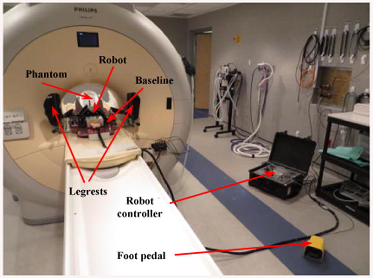
Experimental setup for the MRI compatibility test in the 3.0 T MRI scanner. Phantom, baseline, legrests, robot, controller, and foot pedal.
The experimental conditions are:
Baseline: a patient board with two embedded aluminum rails is set inside the scanner along with the PIQT phantom. A qualitative image set is acquired to evaluate the image interference and this premise is repeated for every session of the experiment.
Baseline with leg rests: a pair of leg support is mounted on the patient board.
Baseline with robot: the robot is mounted (having four ultrasonic motors accompanied with some aluminum and brass screws, nuts, and shafts) by sliding on the designated rails on the board and locked in place.
Controller (not powered): the controller is placed inside the MR room by connecting all wires and cables to the robot but everything is still kept unpowered.
Controller (Powered, E-stop ON): the controller is now powered ON but the motors still have no power and no motion since the E-stop is ON.
Controller (Powered, E-stop OFF): motor power is enabled by turning off the E-stop but the motors are not in motion.
During the Motion: motors are commanded by running at a constant speed of 100 (rpm) until the MR images are entirely acquired. The robot's belts are decoupled to allow continuous rotation of the motors during the full imaging cycle. Figure 12 displays the experimental setup for the MRI compatibility test inside the 3.0 T MR scanner.
We placed the phantom inside the scanner in such a way to replicate the needle placement within the robot's workspace during the real clinical workflow. In this qualitative study the 4 image sequences are used to evaluate the SNR results for 7 configurations. a) T1-weighted FFE (T1W FFE) with fat selective per pulse for z-frame image (TR/TE = 12 ms/2.02 ms; image matrix = 256 × 256; Field of View = 160 × 160 mm2; slice thickness = 2 mm; pixel bandwidth = 399 Hz/pixel); b) T2-weighted 2D Turbo Spin Echo for initial (T2W TSE Init) scan (TR/TE = 4800 ms/100 ms; image matrix = 320 × 320; Field of View = 160 × 160 mm2; slice thickness = 3 mm; pixel bandwidth = 203 Hz/pixel); c) T2-weighted 2D Turbo Spin Echo for needle (T2W TSE Needle) confirmation image (TR/TE = 3030 ms/106 ms; image matrix = 320 × 256; Field of View = 240 × 192 mm2; slice thickness = 3 mm; pixel bandwidth = 260 Hz/pixel); and d) Balanced FFE sequence (TFE RT Circle) for real-time imaging for needle guidance (TR/TE = 3.96 ms/1.98 ms; image matrix = 128 × 128; Field of View = 200 × 200 mm2; slice thickness = 5 mm; pixel bandwidth = 908 Hz/pixel).
Figure 13 displays MR images for 4 MR images under different conditions discussed in Fig. 12. There are relatively less image degradations except the last column (on right) depicting a slight change in the image while running 4 motors simultaneously during the MR image acquisition.
Figure 13.
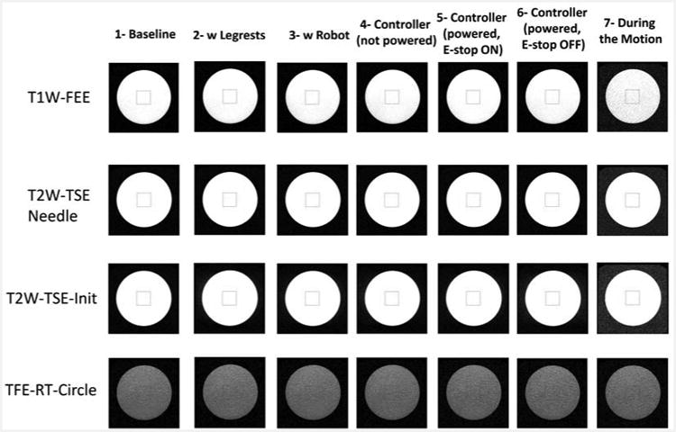
Phantom image from the SNR test under different conditions.
The mean pixel value in the measurement region of interest (MROI) in the original image (minus the baseline offset pixel, if applicable) is called the image signal. The method applied for calculating the SNR is using a proper correction factor multiplied by the mean value of the background region such as [31]:
| (22) |
The normalized values for SNR results are shown in Fig. 14 for the seven configurations. Note that the SNR is quite stable with a variation of no more than 15.35% for the first six states. Since this robot is only intended to align the needle and not actively manipulate it during imaging, reduced SNR of live imaging during motion (State 7) will never occur in a clinical practice with this system.
Figure 14.
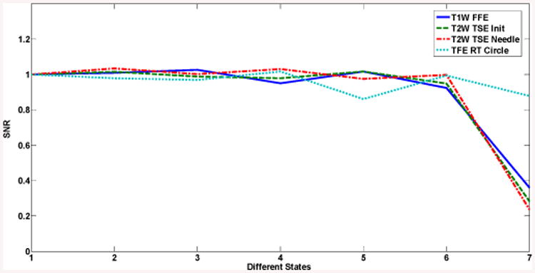
SNR results for different states: 1) Baseline; 2) With leg supports; 3) With robot; 4) Controller (not powered); 5) Controller (powered, E-stop ON); 6) Controller (powered, E-stop OFF); 7) During motion.
The current prototype is designed to be incorporated with a closed-bore 3.0 T MRI scanner (MAGNETOM Verio, Siemens Healthcare, Erlangen, Germany) having 70 cm bore size. Figure 15 displays the volunteer's situation in corporation with the manipulator placing in the supine position while the legs resting in the leg supports and the fiducial white frame is placed next to his perineum. In the previous prototype there was a collision between the volunteer's legs and the robot. This is resolved in the current version so that the manipulator is able to move laterally without any collision and having larger environment to maneuver.
Figure 15.
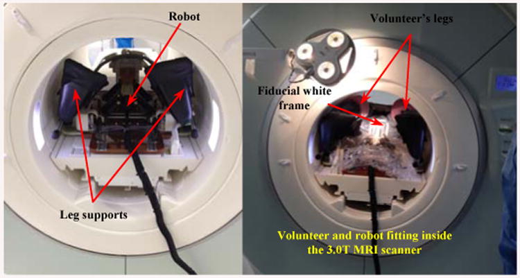
Volunteer-manipulator compatibility inside the 3.0 T MRI scanner (70 cm bore).
Figure 16 demonstrates the robot placing on the scanner board interacting with the patient or a volunteer here. As illustrated, the robot can freely move within the space between the patient's legs and take different configurations for the needle placement.
Figure 16.
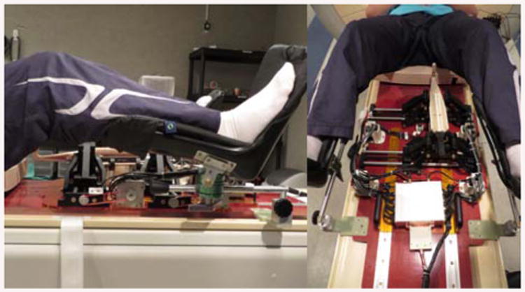
Robot placed on the MRI scanner board in interaction with the patient (as a volunteer herein).
Conclusions
In this paper we proposed a new generation of the MRI-compatible surgical manipulator aimed for the transperineal percutaneous prostate biopsy interventions. The system is composed of 4-DOF trapezoid manipulator composed of 2 similar U-shape frames making 2-DOF Cartesian and 2-DOF angulation motions. In order for this robot to be clinically used for patients, we expect the minimum needle's tip deviation in air (∼ 1 mm) and further in the tissue (∼ 2-3 mm). A series of experimental evaluations are carried out on the robot. The analyzed data and the corresponding results could validate the precision of the manipulator with a maximum translational error of 0.73 mm and angular error of 0.272° in air at the needle's tip by knowing the accuracy of the optical tracker system is about 0.1 mm [21]. However, this could be improved after identifying and resolving the error sources such as the limit switch, lead-screw backlash and overall manufacturing inaccuracies such as ball-joint tolerance, robot controller and encoder's resolution, kinematics parameters, and registration error. Besides the precision and repeatability evaluation of the robot, the robot has undergone the MRI compatibility and collision tests resulting in a quality image even for different conditions. In the next level, the performance and accuracy of the robot will be evaluated in the clinical procedures.
Figure 6.
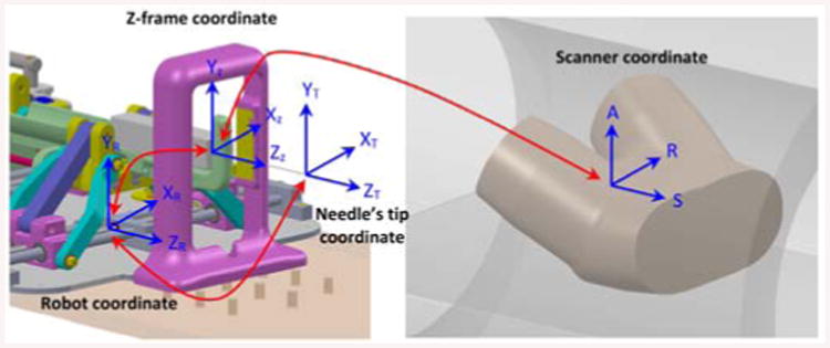
Needle's tip, robot, z-frame and scanner coordinates and their associated transformations.
Acknowledgments
We would like to acknowledge that this work has been funded by NIH R01 CA111288 (BRP) and P41EB015898 (National Center for Image Guided Therapy).
Nobuhiko Hata is a member of the Board of Directors of AZE Technology and has an equity interest in the company. AZE Technology develops and sells imaging technology and software.
Authors would like to thank Alex Camilo and Kevin Harrington for their contributions on the hardware and control system.
Footnotes
Hata's interests were reviewed and are managed by the Brigham and Women's Hospital and Partners HealthCare in accordance with their conflict of interest policies.
Contributor Information
Sohrab Eslami, Laboratory for Computational Sensing and Robotics (LCSR) at the Johns Hopkins University, Baltimore, MD, USA.
Weijian Shang, Automation and Interventional Medicine (AIM) Laboratory in the Department of Mechanical Engineering, Worcester Polytechnic Institute, Worcester, MA, USA.
Gang Li, Automation and Interventional Medicine (AIM) Laboratory in the Department of Mechanical Engineering, Worcester Polytechnic Institute, Worcester, MA, USA.
Nirav Patel, Automation and Interventional Medicine (AIM) Laboratory in the Department of Mechanical Engineering, Worcester Polytechnic Institute, Worcester, MA, USA.
Gregory S. Fischer, Automation and Interventional Medicine (AIM) Laboratory in the Department of Mechanical Engineering, Worcester Polytechnic Institute, Worcester, MA, USA
Junichi Tokuda, Surgical Navigation and Robotics Laboratory, Department of Radiology, Brigham and Women's Hospital, Harvard Medical School, Boston, MA 02115 USA.
Nobuhiko Hata, Surgical Navigation and Robotics Laboratory, Department of Radiology, Brigham and Women's Hospital, Harvard Medical School, Boston, MA 02115 USA.
Clare M. Tempany, Surgical Navigation and Robotics Laboratory, Department of Radiology, Brigham and Women's Hospital, Harvard Medical School, Boston, MA 02115 USA
Iulian Iordachita, Laboratory for Computational Sensing and Robotics (LCSR) at the Johns Hopkins University, Baltimore, MD, USA.
References
- 1.Siegel R, Ma J, Zou Z, Jemal A. Cancer statistics, 2014. CA Cancer J Clin. 2014 Jan-Feb;64(1):9–29. doi: 10.3322/caac.21208. Epub 2014 Jan 7. [DOI] [PubMed] [Google Scholar]
- 2.Schneider CM, Okamura AM, Fichtinger G. IEEE International Conference on Robotics and Automation (ICRA) New Orleans, LA: Apr, 2004. A robotic system for transrectal needle insertion into the prostate with integrated ultrasound; pp. 365–370. [Google Scholar]
- 3.Fichtinger G, Fiene J, Kennedy CW, Kronreif G, Iordachita I, Song DY, Burdette EC, Kazanzides P. Robotic assistance for ultrasound guided prostate brachytherapy. Journal of Medical Image Analysis. 2008 Oct;12(5):535–545. doi: 10.1016/j.media.2008.06.002. [DOI] [PMC free article] [PubMed] [Google Scholar]
- 4.Fichtinger G, Burdette EC, Tanacs A, Patriciu A, Mazilu D, Whitcomb LL, Stoianovici D. Robotically assisted prostate brachytherapy with transrectal ultrasound guidance – phantom experiments. Brachytherapy. 2006;5:14–26. doi: 10.1016/j.brachy.2005.10.003. [DOI] [PubMed] [Google Scholar]
- 5.van den Bosch MR, Moman MR, van Vulpen M, Battermann JJ, Duiveman E, van Schelven LJ, de Leeuw H, Lagendijk JJW, Moerland MA. MRI-guided robotic system for transperineal prostate interventions: proof of principle. Phys Med Biol. 2010 Feb;55:N133–N140. doi: 10.1088/0031-9155/55/5/N02. [DOI] [PubMed] [Google Scholar]
- 6.Beyersdorff D, Winkel A, Hamm B, Lenk S, Loening SA, Taupitz M. MR Imaging-guided Prostate Biopsy with a Closed MR Unit at 1.5 T: Initial Results. Radiology. 2005 Feb;234(2):576–581. doi: 10.1148/radiol.2342031887. [DOI] [PubMed] [Google Scholar]
- 7.Yiallouras C, Mylonas N, Damianou C. MRI-compatible positioning device for guiding a focused ultrasound system for transrectal treatment of prostate cancer. Int Journal of Computer Assisted Radiology and Surgery. 2013 Dec;9(4):745–753. doi: 10.1007/s11548-013-0964-x. [DOI] [PubMed] [Google Scholar]
- 8.Yiallouras C, Damianou C. Review of MRI positioning devices for guiding focused ultrasound systems. Int Journal of Medical Robotics and Computer Assisted Surgery. 2014 Jul 7; doi: 10.1002/rcs.1601. [DOI] [PubMed] [Google Scholar]
- 9.Stoianovici D, Kim C, Srimathveeravalli G, Sebrecht P, Petrisor D, Coleman J, Solomon SB, Hricak H. “MRI Stealth” robot for prostate interventions. J of Minimally Invasive Therapy and Allied Technologies. 2007;16(4):241–248. doi: 10.1080/13645700701520735. [DOI] [PMC free article] [PubMed] [Google Scholar]
- 10.Krieger A, Iordachita I, Guion P, Singh AK, Kaushal A, Menard C, Pinto PA, Camphausen K, Fichtinger G, Whitcomb LL. An MRI-compatible robotic system with hybrid tracking for MRI-guided prostate intervention. Transactions on Biomedical Engineering. 2011 Nov;58(11):3049–3061. doi: 10.1109/TBME.2011.2134096. [DOI] [PMC free article] [PubMed] [Google Scholar]
- 11.Fischer GS, Iordachita I, Csoma C, Tokuda J, DiMaio SP, Tempany CM, Hata N, Fichtinger G. MRI-compatible pneumatic robot for transperineal prostate needle placement. Transactions on Mechatronics. 2008;13(3):295–305. doi: 10.1109/TMECH.2008.924044. [DOI] [PMC free article] [PubMed] [Google Scholar]
- 12.Song SE, Chon NB, Fischer GS, Hata N, Tempany C, Fichtinger G, Iordachita I. Development of a pneumatic robot for MRI-guided transperineal prostate biopsy brachytherapy: new approaches. IEEE International Conference on Robotics and Automation (ICRA) 2010 Jun;2:2580–2586. doi: 10.1109/ROBOT.2010.5509710. [DOI] [PMC free article] [PubMed] [Google Scholar]
- 13.Patriciu A, Petrisor D, Muntener M, Mazilu D, Schär M, Stoianovici D. Automatic brachytherapy seed placement under MRI guidance. IEEE Transactions on Biomedical Engineering. 2007 Aug;54(8):1499–1506. doi: 10.1109/TBME.2007.900816. [DOI] [PMC free article] [PubMed] [Google Scholar]
- 14.Su H, Iordachita I, Yan X, Cole GA, Fischer GS. 33rd Ann Int Conf IEEE EMBS. Boston, MA: 2011. Reconfigurable MRI-guided robotic surgical manipulator: prostate brachytherapy and neurosurgery applications; pp. 2111–2114. Aug. 30-Sep. 3. [DOI] [PubMed] [Google Scholar]
- 15.Li G, Su H, Shang W, Tokuda J, Hata N, Tempany CM, Fischer GS. A fully actuated robotic assistant for MRI-guided prostate biopsy and brachytherapy. Proceedings of the SPIE. 2013 Mar 12;8671:8. doi: 10.1117/12.2007669. [DOI] [PMC free article] [PubMed] [Google Scholar]
- 16.Su H, Cardona DC, Shang W, Camilo A, Cole GA, Rucker DC, Webster RJ, Fischer GS. IEEE International Conference on Robotics and Automation (ICRA) Saint Paul, MN: May 14-18, 2012. A MRI-guided concentric tube continuum robot with piezoelectric actuation: a feasibility study; pp. 1939–1945. [Google Scholar]
- 17.Goldenberg AA, Trachtenberg J, Kucharczyk W, Yi Y, Haider M, Ma L, Weersink R, Raoufi C. Robotic system for closed bore MRI-guided prostatic interventions. IEEE/ASME Transactions on Mechatronics. 2008 Jun;13(3):374–379. [Google Scholar]
- 18.Tadakuma K, DeVita LM, Plante JS, Shaoze Y, Dubowsky S. In Proc IEEE International Conference on Robotics and Automation (ICRA) Pasadena, CA: May 19-23, 2008. The experimental study of a precision parallel manipulator with binary actuation: With application to MRI cancer treatment; pp. 2503–2508. [Google Scholar]
- 19.Eslami S, Fischer GS, Song SE, Tokuda J, Hata N, Tempany CM, Iordachita I. IEEE International Conference on Robotics and Automation (ICRA) Karlsruhe, Germany: May 6-10, 2013. Towards clinically optimized MRI-guided surgical manipulator for minimally invasive prostate percutaneous interventions: constructive design; pp. 1228–1233. [DOI] [PMC free article] [PubMed] [Google Scholar]
- 20.Song SE, Cho N, Tokuda J, Hata N, Tempany C, Fichtinger G, Iordachita I. Preliminary evaluation of a MRI-compatible modular robotic system for MRI-guided prostate interventions. Proc. IEEE RAS and EMBS, Int. Conf. Biomed. Rob. Biomech; Tokyo, Japan. Sep. 26-29, 2010; [DOI] [PMC free article] [PubMed] [Google Scholar]
- 21.States RA, Pappas E. Precision and repeatability of the Optotrak 3020 motion measurement system. Journal of Medical Engineering and Technology. 2006 Jan-Feb;30(1):11–16. doi: 10.1080/03091900512331304556. [DOI] [PubMed] [Google Scholar]
- 22.Chassat F, Lavallee S. Experimental protocol of accuracy evaluation of 6-D localizers for computer-integrated surgery: application to four optical localizers. Medical Image Computing and Computer-Assisted Intervention – MICCAI98. 1998;1496:277–284. [Google Scholar]
- 23.Conrad KL, Shiakolas PS, Yih TC. Proc of the 8th Mediterranean Conf on Control and Automation (Med 2000) Rio, Patras, Greece: Jul 17-19, 2000. Robotics calibration issues: accuracy, repeatability, and calibration; p. 6. [Google Scholar]
- 24.Seifabadi R, Cho NB, Song SE, Tokuda J, Hata N, Tempany CMC, Fichtinger G, Iordachita I. Accuracy study of a robotic system for MRI-guided prostate biopsy, Int. Journal of Medical Robotics and Computer Assisted Surgery. 2013 Sep;9(3):305–316. doi: 10.1002/rcs.1440. [DOI] [PMC free article] [PubMed] [Google Scholar]
- 25.Masamune K, Fichtinger G, Patriciu A, Sakuma I, Dohi T, Stoianovici D. System for robotically assisted percutaneous procedures with computed tomography guidance. Journal of Computer Aided Surgery. 2001;6(6):370–383. doi: 10.1002/igs.10024. [DOI] [PubMed] [Google Scholar]
- 26.Su H, Cardona DC, Shang W, Camilo A, Cole GA, Rucker DC, Webster RJ, Fischer GS. International Conference on Robotics and Automation. Saint Paul, MN: May 14-18, 2012. A MRI-guided concentric tube continuum robot with piezoelectric actuation: a feasibility study; pp. 1939–1945. [Google Scholar]
- 27.Cole G, Harrington K, Su H, Camilo A, Pilitsis J, Fischer GS. 12th International Symposium on Experimental Robotics (ISER2010) New Delhi & Agra, India: Dec, 2010. Closed-loop actuated surgical system utilizing real-time in-situ MRI guidance; pp. 785–798. [Google Scholar]
- 28.Fischer G, Cole G, Su H. Approaches to creating and controlling motion in MRI. Conference of the IEEE Engineering in Medicine and Biology Society, (EMBC), 2011 Annual International Conference of the IEEE. 2011:6687–6690. doi: 10.1109/IEMBS.2011.6091649. [DOI] [PubMed] [Google Scholar]
- 29.Greenway B. Tutorial: robot accuracy. Industrial Robot: An International Journal. 2000;27(4):257–265. [Google Scholar]
- 30.Shiakolas PS, Conrad KL, Yih TC. On the accuracy, repeatability, and degree of influence of kinematics parameters for industrial robots, Int. Journal of Modeling and Simulation. 2002;22(3):1–10. [Google Scholar]
- 31.National Electrical Manufacturers Association (NEMA) Standards Publication MS 1-2008. Determination of Signal-to-Noise Ratio (SNR) in Diagnostic Magnetic Resonance Imaging [Google Scholar]
- 32.Tokuda J, Fischer GS, Papademetris X, Yaniv Z, Ibanez L, Cheng P, Liu H, Blevins J, Arata J, Golby A, Kapur T, Pieper S, Burdette EC, Fichtinger G, Tempany CM, Hata N. OpenIGTLink: An Open Network Protocol for Image-Guided Therapy Environment. Int Journal of Med Robot. 2009;5(4):423–34. doi: 10.1002/rcs.274. [DOI] [PMC free article] [PubMed] [Google Scholar]


