Abstract
Floating dosage forms are an important formulation strategy for drugs with a narrow absorption window and low intestinal solubility, and for localized gastric treatment. Novel floating pellets were prepared using the hot-melt extrusion (HME) technology. Uniformly foamed strands were created by liquid injection pumping and screw configuration modification. The ammonio methacrylate copolymer (Eudragit® RSPO) foaming structure was formed by a liquid-vapor phase transition inside the strand upon die exiting resulting from the sudden decrease in external pressure, vaporizing the liquid ethanol and vacating the extruded material. This generated uniform vacuous regions in the extrudate. The pellets’ internal structure was investigated using scanning electron microscopy (SEM). The formulation constituents’ and processing parameters’ effects on the drug release profiles, floating force, and the pellets’ micromeritic properties were evaluated by design of experiments: all formulations showed zero lag time and excellent floating strength, indicating immediate-floating pellet formation. The pellets’ drug release profiles were controlled by multiple independent variables at different time points (≤24 h). Drug loading significantly affected drug release within the first hour; the hydroxypropyl methylcellulose (HPMC) content thereafter. Understanding the variables’ effects on the formulations allows for the tailoring of this delivery system to obtain various drug release profiles.
Keywords: Hot-melt extrusion, Foamed extrudate, Floating drug delivery system, Controlled release, Eudragit® RSPO, Chemical imaging, Theophylline
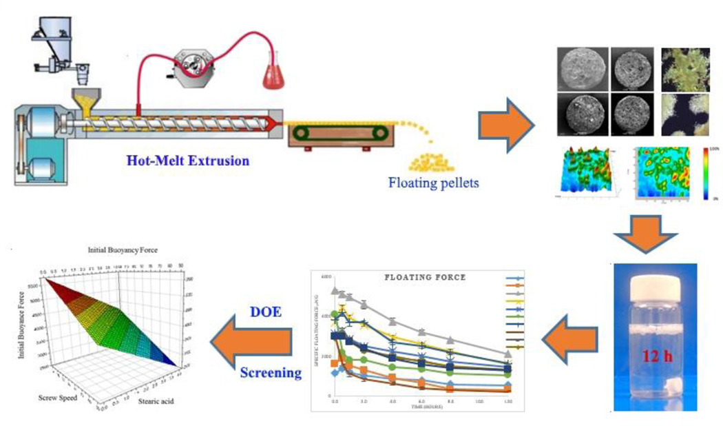
Graphical abstract
Introduction
Solid oral controlled-release dosage forms are the most preferred and reliable dosage forms because of their inherent advantages, such as the reduction of side effects, unassisted administration, improvement of patient compliance, treatment cost reduction, and their flexible drug delivery system design. However, biological variations are challenging factors in controlling the dosage form. Among these, individual variations in the gastrointestinal tracttransition times, which can vary from minutes to hours [1], are most likely the primary source of these fluctuations.
The drugs most susceptible to these fluctuations are those with either a narrow absorption window in the upper part of the gastrointestinal tract [2], those that are locally active in the stomach, unstable in the intestinal or colonic environment, or with a low solubility in a relatively high pH environment [3]. Such drugs need to reside in the stomach for an extended period to gradually deliver the appropriate amounts of the active pharmaceutical ingredient (API) to the absorption site, promote the desired effect(s) in the stomach region itself, or to be dissolved completely before entering an environment where further dissolution is necessary. A substantial increase in the stomach residence time of the dosage form is possibly the single most significant strategy when attempting to overcome the above-mentioned drawbacks of conventional dosage forms. Gastro-retentive drug delivery systems (DDS) offer several advantages over the conventional dosage forms, such as a continuous, controlled drug supply to the absorption sites, reduced drug plasma concentration fluctuations, and improved bioavailability [4]. Numerous approaches can prolong the retention time of DDS in the stomach [2], [5] including a) floating DDS, which have a relatively low density and float atop the existing gastric fluid, b) a mucoadhesive system that can attach itself to the gastric epithelium to avoid gastric emptying events, c) swelling DDS, which have been shown to efficiently absorb the gastric fluid and become larger than the pyloric sphincter, thereby preventing the physical forcing of the dosage form through the pyloric orifice, and d) high-density DDS that sink to the lower part of the stomach and remain there because of the combination of the dosage form’s density and its location relative to the pyloric sphincter. Among these, floating DDS are considered the most favorable as they do not interfere with the physiological activity of the gastro-intestinal tract, nor are they likely to be removed because of a temporary elevation of the dosage form. It has been previously reported that the floating dosage forms significantly prolong the gastro-retention time [6–9] and also improve bioavailability [10,11]. Therefore, floating DDS are suitable dosage forms for controlled-release oral dosage forms [12].
Floating DDS can be further sub-classified as either monolithic or multi-unit DDS. Though most of the marketed gastro-retentive drug products are monolithic, multi-unit systems are more advantageous than their counterparts [13]. The monolithic dosage forms are unreliable and lack reproducibility when attempting to extend the gastric residence time because of their “all-or-nothing” presence with regard to the gastric emptying process. In contrast, multi-unit systems can reduce the intersubject absorption variability and lower the probability of dose-dumping [12]. Additionally, the small size of floating units has been speculated to be superior in extending the residence time in the stomach [14]. This would certainly minimize the risk of treatment failure and enhance the safety of the dosage form. Moreover, multi-unit dosage forms not only enhance formulation flexibility, but also allow for a tailored drug release profile and the incorporation of various APIs into a single dosage form.
Hot-melt extrusion (HME) has recently emerged as a novel processing technology in the development of molecular dispersions in polymer and lipid carriers for the preparation of controlled, modified, extended, and targeted drug delivery [15–18]. This processing approach may be an excellent alternative to other more conventional techniques, such as roll spinning and spray drying [19]. Additionally, HME has significant potential as a continuous process, the value of which has been recognized globally in the pharmaceutical industry [20]. The processing flexibility of an HME with various functions and customization potential enables it to be used innovatively and for special or particular purposes.
In this study, floating pellets were prepared by HME in conjunction with liquid-vapor phase transitions and polymer expansion at elevated temperatures. Ammonio methacrylate copolymer (Eudragit® RSPO), stearic acid, and hydroxypropyl methylcellulose (HPMC) K15M were used as an insoluble matrix former, a processing aid, and to control the drug release from the matrix, respectively. The pellets’ physicochemical properties, such as their dissolution profiles, buoyancy strenght, specific surface area, polymorphism of the API, and drug distribution within the matrix were determined. Furthermore, the strand cross cut was imaged by using SEM. Design of experiments (DoE) was used to elucidate the effects of the formulation constituents and critical processing parameters on the physicochemical properties.
Materials and Methods
Materials
Anhydrous theophylline (THEO) and stearic acid were purchased from Acros Organic (Thermo Fisher Scientific, NJ, USA). Ethyl cellulose N7, polyethylene oxide (Polyox WSR 301), and hyproxypropyl methylcellulose (HPMC K15M) were kindly provided by Colorcon, Inc. (Harleysville, PA, USA). Ammonio methacrylate copolymer type B (Eudragit® RSPO, Eudragit®RLPO) was gifted by Evonik Corporation (Parsippany, NJ, USA). Polyvinyl acetate/polyvinyl pyrrolidone (Kollidon®SR) was generously supplied by BASF Corporation (Florham Park, NJ, USA). Hydroxypropyl cellulose (HPC MF) was gifted by Ashland, Inc. (Lexington, KY, USA). All other reagents used in the study were of analytical grade and were purchased from Fisher Scientific (Pittsburgh, PA, USA).
Extrusion Processing
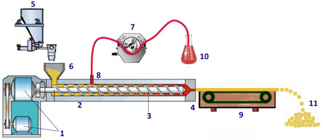
The system used for preparing the foamed strands is illustrated in Fig. 1. The main module is a twin screw extruder (Process 11™, Thermo Fisher Scientific, Odessa, TX, USA). The die was equipped with a 1.5 mm circular insert. The peristaltic pump (IPC, Ismatec IDEX Corp., Glattbrugg, Switzerland), chiller, feeder, and conveyor belt were assembled as a synchronized and continuous system. The screw speed, feeding rate, barrel temperature profile, die pressure, die temperature, and torque were monitored by the control unit.
Fig. 1.
Schematic representation of the foamed pellet manufacturing process. (1) Motor, (2) Barrel, (3) Screws, (4) Die, (5) Feeder, (6) Hopper, (7) Peristaltic Pump, (8) Liquid Injection Port (at zone 3), (9) Conveyor Belt, (10) Foaming Agent Vessel, (11) Foamed Pellets.
Initially, all materials were sieved (USP #35 mesh) to remove potential aggregates in the material. For each formulation, 100 g of the physical mixture were weighed and geometrically diluted until a homogenized mixture was obtained.
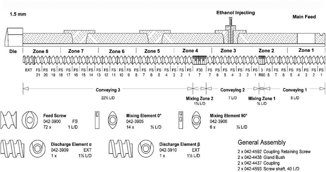
A modified screw configuration (Fig. 2) was used for the experiment. The liquid injection port was set at zone 3. The zone temperature on the barrel from the hopper to the die were set to 10, 30, 30, 30, 50, 80, 100, and 110 °C for zone 1 to zone 8, respectively. The die temperature, screw speed, feeding rate, and the liquid injection rate were investigated in the ranges as shown in Table 1.
Fig. 2.
Hot-Melt Extrusion screw design and zone designations.
Table 1.
Experimental Factors and Ranges of Variation
| Independent Variable | Symbol | Unit | Upper Level (+1) |
Lower Level (−1) |
|---|---|---|---|---|
| Die Temperature | X1 | °C | 140 | 110 |
| Screw Speed | X2 | rpm | 120 | 50 |
| Feeding Rate | X3 | g/min | 4 | 2 |
| Injection Rate | X4 | % (w/w) | 8 | 4 |
| Drug Loading | X5 | % | 40 | 20 |
| HPMCa Content | X6 | % | 6 | 0 |
| Stearic Acid Content | X7 | % | 4 | 0 |
Hydroxypropyl methylcellulose
Prior to processing, the system was allowed to heat-soak to attain the thermal equilibrium. To ensure that the extruder had reached a steady state prior to collecting samples, the first 30 g of the extrudate were discarded. The conveyor speed was adjusted to synchronize with the extruder’s throughput to obtain uniformly cylindrical extrudates. The strands were subsequently manually cut to 1.5–2.0 mm long cylinders and preserved in amber glass bottles at ambient temperature. The schematic diagram (Fig. 3) represents the overall process of the floating pellet formation.
Fig. 3.
The mechanism underlying foamed strand formation during processing.
Preformulation
Thermogravimetric Analysis (TGA) and Differential Scanning Calorimetry (DSC) were used to confirm the compatibility of the API and the excipients as well as their thermal stability during extrusion. The pure components, their binary mixtures (1:1), and complete physical mixtures were subjected to TGA (Pyris 1 Perkin Elmer, Waltham, MA, USA). Samples weighing 5–10 mg were heated from 25 °C to 200 °C at a ramp rate of 10 °C/min in a platinum pan under an inert nitrogen atmosphere at a flow rate of 20 mL/min. The samples were held at 200 °C for 5 min. DSC (Diamond Perkin Elmer, Waltham MA, USA) was used to confirm the TGA results. Samples weighing 4–5 mg were placed in hermetically sealed aluminum pans and placed under an inert nitrogen atmosphere at a flow rate of 20 mL/min. The heating cycles were 25 °C to 200 °C at a ramp rate of 10 °C/min; the temperature was maintained at 200 °C for 5 min, and finally the samples were cooled to room temperature at the same rate. The thermograms were analyzed for unanticipated thermal events.
Design of Experiments
DoE was used to address factors that have major effects on the characteristics of the floating pellets and was based on the Plackett–Burman model, which is particularly useful when assessing the main effects for further investigation [21]. The most significant advantage of this model is that many factors can be investigated simultaneously, while employing the minimum number of experiments. In addition, the center points were performed in triplicate for calculating statistical parameters. The regression equation is expressed as follows:
| (1) |
where Yi is the response number i, ai0 is the constant, and ai1, ai2, … ain are the coefficients of the encoded factors X1, X2,…, Xn, respectively. The significance of the model and factors were determined by multi-linear regression and one-way ANOVA with the assistance of Modde 8.0 software (Umetrics Inc., Sweden). Seven independent variables were investigated, i.e., the screw speed, feeding rate, die temperature, drug loading, % HPMC, % stearic acid, and ethanol injection rate. The responsive variables were the drug release profile, micromeritic properties, and floating strengths.
Quantitative Analysis of Theophylline
The extruded material was milled to a fine powder and a quantity equivalent to 100 mg of THEO was used for the analysis. This material was then transferred to a 100-mL volumetric flask along with 60 mL methanol and 20 mL water. The vessel was subsequently sonicated for 2 min, until no particulate matter was visible (Branson 2510, Branson Ultrasonic Corp., Danbury, CT, USA). A volume of liquid was removed and centrifuged at 12,000 rpm for 5 min at 25 °C (Centrifuge 5415R, Eppendorf AG, Eppendorf, Germany). The supernatant was diluted 10 times with the mobile phase prior to high-performance liquid chromatography (HPLC) analysis.
HPLC Analysis
A Waters 600 HPLC system (Waters Corp., Milford, MA, USA) equipped with an autosampler, UV/VIS detector, and a Phenomenex® Luna C18 (5 µm, 250 mm × 4.6 mm) column was used to analyze THEO. The HPLC program was developed by minor modification of the USP method. The elution was performed with a mixture of acetonitrile and acetate buffer (2.72 g of sodium acetate trihydrate and 10.0 mL of glacial acetic acid solution in a 2000 mL solution) at a ratio of 30:70 (v/v) in an isocratic mode. The flow rate was maintained at 1.0 mL/min and the injection volume was 10 µL. The signal was detected at a wavelength of 271 nm. A seven-point calibration curve was linear in the 2.1 µg/mL–131 µg/mL range with a correlation coefficient (R2) of 0.9995.
In Vitro Drug Release
Hard gelatin capsules (size 0) filled with floating pellets equal to 100 mg THEO were subjected to dissolution testing in a medium consisting of 900 mL 0.1N HCl. A USP dissolution apparatus II (Hanson SR8; Hanson Research, Chatsworth, CA, USA) was used with a temperature maintained at 37 ± 0.5 °C and a paddle rotation speed set to 100 rpm. At predetermined intervals, a volume of 2.0 mL dissolution media was withdrawn and 2.0 mL of fresh dissolution media was added. The samples were subsequently filtered through 0.2 µm, 13 mm PTFE membrane filters (Whatman, Inc., Haverhill, MA, USA) and a volume of 10 μL was injected into the HPLC system for analysis as per the above stated HPLC method.
Chemical Imaging and Fourier Transform Infrared Spectroscopy Analysis
Infrared spectra were collected using a bench top Fourier transform infrared (FTIR) spectrometer (Agilent Technologies, Cary 660; Agilent, Santa Clara, CA, USA) fitted with a MIRacle ATR sampling accessory (Pike Technologies, Madison, WI, USA). The bench top ATR was equipped with a single bounce diamond-coated ZnSe internal reflection element. Chemical images were collected using an infrared microscope (Agilent Technologies, Cary 620 IR; Agilent, Santa Clara, CA, USA) equipped with a 64 × 64 focal plane array detector. The images were collected with a germanium micro ATR sampling accessory, providing a field of view (FOV) of approximately 70 × 70 μm with 1.1 μm spatial resolution.
Hot-Stage Polarized Light Microscopy
An optical microscope (Agilent Cary 620 IR; Agilent, Santa Clara, CA, USA) was equipped with an electronically controlled hot-stage (T95 LinkPad and FTIR 600; Linkam, Tadworth, UK). Images were collected with and without crossed polarizers to assess the crystalline API content. The samples were heated to 200 °C at a ramp rate of 20 ± 0.1 °C/min and the temperature was maintained until the visual analysis was complete.
Scanning Electron Microscopy
The samples were mounted on an aluminum stubs held with a carbon adhesive film. Gold was used to coat the samples by a Hummer® 6.2 sputtering system (Anatech LTD., Battlecreek, MI, USA) in a high-vacuum evaporator. The surface topography of each sample was analyzed by a scanning electron microscope (SEM) operating at an accelerating voltage from 1.0 kV to 5.0 kV (JEOL JSM-5600; JEOL, Inc., Peabody, MA, USA).
Powder X-Ray Diffraction
Powder X-ray diffraction (PXRD) was performed using a Bruker D8 Advance (Bruker, Billerica, MA, USA) with a Cu-source theta-2theta diffractometer equipped with a Lynx-eye PSD detector. The generator was set to a voltage of 40 kV and a current of 30 mA. The samples were dispersed on a low background Si sample holder and compacted gently with the back of a metal spatula. The scan ran from 5°–40° 2θ with a 0.05 step size at 3 s per step.
Floating Strength Determination
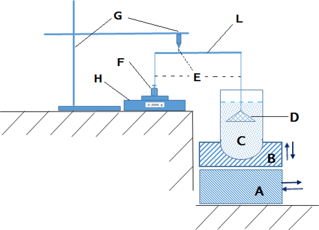
The “resultant-weight” measuring apparatus and method was first proposed by Timmermans [22], which has been modified in the last decade [23, 24]. For this study, a resultant-weight measuring apparatus which based on the lever principle was assembled (Fig. 4). The five-point calibration curve was established from the displayed value and the counterpoise weights that attach to the cone-suspended string. Using a USP dissolution apparatus II (Hanson SR8; Hanson Research, Chatsworth, CA, USA), 500 mg of floating pellets were stirred in 900 mL 0.1N HCl at 37 ± 0.5 °C and 100 rpm in the dissolution vessel. At predetermined intervals, the vessel was removed from the dissolution system to measure the floating force. The vessel was first carefully installed into the apparatus by placing it firmly on the vessel holder and was slowly raised to ensure that all floating pellets were collected under the completely submerged cone. The basement was moved to its position to support the vessel holder and the procedures continued after the cone was steady. The floating strength was calculated by entering the value displayed on the balance in the regression equation derived from the calibration curve. The vessel was placed back into the dissolution system to allow continuous stirring until the next measurement.
Fig. 4.
Schematic representation of the instrument used for measuring the floating force. (A) Base Plate, (B) Vessel Holder, (C) Dissolution Vessel, (D) Perforated Stainless Steel Cone, (E) Flexible Nylon Connector, (L) Lever, (G) Stand, (H) Electronic Balance, (F) Counterpoise.
Surface Area Measurement
The specific sample surface area measurement was based on the Brunauer-Emmett-Teller (BET) equation of isothermal gas adsorption [25]. The Gemini VII Surface Area and Porosity system (Micromeritics, Norcross, GA, USA) equipped with a FlowPrep 060 sample degas unit and ultrahigh purity nitrogen and helium gas supplies was used and the data were analyzed using the Gemini VII 2930 software suite (Micromeritics, Norcross, GA, USA).
Densities and Porosity
To measure the geometric density, the straight strands were carefully cut in to 2 cm cylinders to ensure the flat surface on both sides of the cylinders. The diameter (d) and length (h) of the cylinder strands were measured by digital caliper with d=0.01mm (VWR Digital Caliper, Radnor, PA, USA). The weight of the strands (m) was measured by a high precision balance (Analytical Balance XSE 204, Mettler Toledo, Switzerland). The geometric density was calculated by the following equation:
| (2) |
To determine the tap density, 10 g of each formulation was accurately weighed (m) and transfer to 50 ml cylinder. The cylinder was then tapped carefully by hand until the volume (v) was constant (at least 50 times). The tap density was calculated by the following equation:
| (3) |
The true density of the floating pellets was measured by a gas pycnometer (AccuPyc II 1340, Micrimeritics, Norcross, GA, USA) using helium gas. The measurements were repeated five times and the data were processed using the above-mentioned software suite. The obtained results reflected the density of the matrix skeleton as the gas occupied the vacuous space within the matrix. The porosity of the floating pellets was calculated using the following equation:
| (4) |
where Vvoid and Vgeometric are the volume of the air pockets and pellet as a whole object, respectively. Dgeometric and Dskeletal are the geometric density and true density of the pellets, respectively.
Result and Discussion
Experimental Parameters
A preliminary study was conducted to determine the feasibility and the requirements for this novel approach. The effects of the critical processing parameters, including screw configurations, injection port placement, and barrel temperature profile were investigated.
With the standard screw configuration, the system was unable to maintain a steady-state process as the large mixing zones, with higher temperatures, retarded the material movement, thus allowing most of the ethanol in the mixture to be vaporized and move backward along the barrel and escape through the feeding hopper. This volatile ethanol might generate unstable pressures at the injection port that led to fluctuations in the liquid ethanol flow. For this reason, the modified screw configuration was designed with two small mixing zones at the very beginning to aid in the homogenization of the formulation components (Fig. 2). Additionally, reversing elements were incorporated into the second mixing zone to facilitate a melt seal, which prevented any gaseous ethanol from traveling backward along the barrel and exiting through the feeding hopper.
Secondly, the selection of the zone for injecting the liquid had an important role in the creation of the foamed structure. The temperature of the injection zone should not be higher than the boiling point of the injected liquid and it should be located as far as possible from the high pressure regions (the die-end of the barrel). It was observed that as the liquid injection site approached near the feeding hopper, gaseous ethanol interfered with the feeding of the mixture. To balance out these requirements, the liquid injection port was placed at zone 3.
Finally, the temperature profile was a key factor in the foam-forming process. The temperature in the injection zone should be enough low to keep the foaming agent in a liquid state. On the other hand, the temperature along the barrel should be enough high to soften the carrier material to prevent the torque from becoming too elevated. More importantly, the temperature of the die was found to play a crucial role in creating the foamed strands. If the temperature at the die was too high, the extrudate would be blown apart by the internal pressure before solidifying enough to maintain its structure. In contrast, if the die temperature was not enough high the extrudate would not be molten to swell. Upon exiting the die, the foamed strands were still soft. To accommodate for this, the strands exiting the die were synchronized with a conveyer belt, which allowed the strands to cool to the point of structural integrity. With this system setup, the torque and die pressure were found to be highly stable. All collected extrudates appeared to be highly uniform.
Extrudate Preparation
In this study, THEO was used as a model drug and insoluble polymers were used as the matrixforming agents. A soluble polymer was used to facilitate water permeability deep into the matrix core and to form a gel structure inside the matrix, which was intended to moderate the drug release from the matrix. In addition, stearic acid was incorporated as a processing aid. Finally, ethanol was used as the foaming agent. The DSC and TGA results (data not shown) confirmed that the API and excipients were thermally stable at 200 °C and no apparent interaction was observed in the thermograms.
In the preliminary experiments, four matrix-forming polymers (Ethyl cellulose N7, Kollidon® SR, Eudragit® RLPO, and Eudragit® RSPO) and three water-soluble polymers (HPMC K15M, HPC MF, and polyox WSR 301) were evaluated. Based on the foamed-strand formation, floating ability, and the dissolution profile of the pellets, Eudragit® RSPO and HPMC K15M were chosen for further investigation. Additionally, numerous polymer ratios were investigated, while process parameters were varied to determine the appropriate ranges for the experimental design. From these preliminary results, seven critical factors and their operation ranges were set up as shown in Table 1.
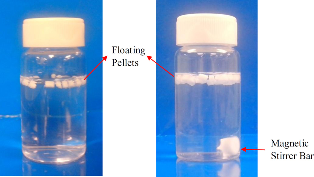
Eleven runs from the experimental design (Table 2) were prepared and characterized. All samples were found to be uniform, foamed structures, which could float on the gastric fluid (Fig. 5) and control the drug release from the matrix over a period of 24 h. The drug content of the extrudates was 97.5% to 100.2% compared to the theoretical values, which further confirmed that the drug was stable during processing. The loss on drying (105 °C for 10 min) of the samples was considerably low, ranging from 0.97% to 1.18%.
Table 2.
Plackett-Burman Experimental Design
| Formulation | X1 | X2 | X3 | X4 | X5 | X6 | X7 |
|---|---|---|---|---|---|---|---|
| F1 | 110 | 50 | 4.0 | 4.0 | 20.0 | 0.0 | 4.0 |
| F2 | 140 | 50 | 2.0 | 8.0 | 20.0 | 6.0 | 4.0 |
| F3 | 140 | 120 | 2.0 | 8.0 | 20.0 | 0.0 | 0.0 |
| F4 | 110 | 50 | 2.0 | 8.0 | 40.0 | 6.0 | 0.0 |
| F5 | 140 | 50 | 4.0 | 4.0 | 40.0 | 0.0 | 0.0 |
| F6 | 110 | 120 | 2.0 | 4.0 | 40.0 | 0.0 | 4.0 |
| F7 | 110 | 120 | 4.0 | 4.0 | 20.0 | 6.0 | 0.0 |
| F8 | 140 | 120 | 4.0 | 8.0 | 40.0 | 6.0 | 4.0 |
| F9 | 125 | 85 | 3.0 | 6.0 | 30.0 | 3.0 | 2.0 |
| F10 | 125 | 85 | 3.0 | 6.0 | 30.0 | 3.0 | 2.0 |
| F11 | 125 | 85 | 3.0 | 6.0 | 30.0 | 3.0 | 2.0 |
Fig. 5.
Photographs of pellets floating in dissolution medium (0.1N HCl) at 37 ± 0.5°C. (A) t = 0 h and (B) after 12 h. Magnetic Stirrer Bar Floating Pellets
In this study, ethanol was used as the foaming agent, since it has a low boiling point and is generally considered a benign solvent. Upon exiting the die, almost all of the ethanol in the formulation vaporized because the extrudate’s temperature (>110 °C) was considerably higher than the boiling temperature of ethanol (78.4 °C). Additionally, the loss on drying of all extrudates (<1.18%) was lower than that of their corresponding physical mixtures (~1.46%), which further confirmed that virtually all ethanol had evaporated from the extrudates during processing.
Micromeritic Properties of the Floating Pellets
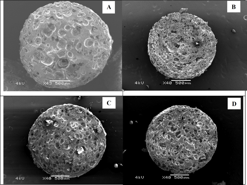
The internal structure of the strands was examined by SEM of the matrix cross-sectional area. Hollow spaces were scattered evenly throughout the entire strand (Fig. 6). The size and pattern of these structures were influenced by multiple variables. It is difficult to determine which factors provide the greatest interaction impacts; however, a high drug loading, high injection rate, and high temperature seem to create smaller openings in larger quantities. This may be due to their effects on the formulation’s polymeric stretching properties.
Fig. 6.
Scanning electron microscopy (SEM) images of the pellets’ cross sectional area. (A) Formulation 1, (B) Formulation 3, (C) Formulation 6, and (D) Formulation 9.
The formation of the air pockets in the strands could be explained by the liquid–gas phase transition and expansion. Inside the barrel, the ethanol was mixed with the formulation to form a uniform mixture. Inside the die, the pressure attained its highest value as the material was forced through a relatively small orifice. The pressure inside the die (28 bar to 35 bar, depending on the experiment) maintained the ethanol in the liquid form despite the temperatures exceeding its boiling point. When exiting the die, the pressure suddenly decreased to atmospheric pressure. The temperature of the strand was sufficiently high to prevent the polymer from becoming rigid or brittle, which allowed it to stretch, but not excessively. This, of course, increased the volume of the extrudate and accelerated the rate at which it cooled as the gaseous ethanol carried heat along with it. The interplay of these events allowed the formation and maintenance of the foamed structures.
Another point to consider is that ethanol also acted as a processing aid. The torque during the process was considerably low and stable, from 1.56 N/m to 2.64 N/m depending on the formulation. Without ethanol, the processing could not be accomplished as the torque requirements exceeded the instrument’s limitations. The reduction in torque allowed for a decrease in the processing temperature. This implies that this technique may be of benefit to those APIs that are not stable at high temperatures.
Although the foamed structures within the matrix could be observed in the SEM images, the degree of foaming could not be determined. The density, specific surface area, and porosity are usually used to evaluate the magnitude of a foaming effect. The skeleton density of all samples was approximately equal to that of the unfoamed pellets. Thus, the processing and composition did not seem to affect the density of the blend. However, the tap density, specific surface area, and porosity varied from formulation to formulation (Table 3). These factors were directly related to the pellets’ floating ability. The regression analysis showed that stearic acid had a highly significant (p < 0.01) effect on both the surface area and porosity. Furthermore, the feeding and injection rate significantly (p < 0.05) affected the specific surface area. On the other hand, the screw speed and drug loading were the two variables that most significantly affected pellet porosity. Contradictory to what was expected, the die temperature had little effect on the porosity characteristics of the pellets.
Table 3.
Micromeritic Properties of the Floating Pellets (±SD)
| Formulation | Tap Density (g/cm3)* |
Geometric density (g/cm3)* |
True Density (g/cm3)** |
Surface Area (m2/g)** |
Porosity (%) |
Loss on Drying (%) |
Drug Loading (%)* |
|---|---|---|---|---|---|---|---|
| F1 | 0.4562 ±0.0137 | 0.898 ±0.036 | 1.276 ±0.005 | 0.0748 ±0.0031 | 0.296 | 1.18 | 20.04 ±0.33 |
| F2 | 0.4270 ±0.0137 | 0.858 ±0.023 | 1.219 ±0.002 | 0.253 ±0.0018 | 0.296 | 1.02 | 19.83 ±0.26 |
| F3 | 0.3003 ±0.0210 | 0.649 ±0.030 | 1.229 ±0.004 | 0.2985 ±0.0012 | 0.472 | 1.17 | 19.51 ±0.13 |
| F4 | 0.3677 ±0.0129 | 0.727 ±0.030 | 1.274 ±0.003 | 0.2543 ±0.0083 | 0.429 | 0.97 | 38.86 ±0.60 |
| F5 | 0.3488 ±0.0150 | 0.759 ±0.016 | 1.266 ±0.008 | 0.1536 ±0.0007 | 0.401 | 1.08 | 39.52 ±0.71 |
| F6 | 0.3860 ±0.0212 | 0.706 ±0.030 | 1.226 ±0.004 | 0.1626 ±0.0117 | 0.424 | 1.11 | 39.14 ±0.41 |
| F7 | 0.4093 ±0.0258 | 0.720 ±0.017 | 1.227 ±0.006 | 0.1721 ±0.0097 | 0.413 | 1.13 | 19.69 ±0.13 |
| F8 | 0.3697 ±0.0196 | 0.768 ±0.016 | 1.258 ±0.004 | 0.1748 ±0.0049 | 0.390 | 1.06 | 39.90 ±0.28 |
| F9 | 0.3800 ±0.0198 | 0.769 ±0.026 | 1.269 ±0.001 | 0.1879 ±0.0058 | 0.394 | 0.95 | 29.51 ±0.25 |
| F10 | 0.3916 ±0.0188 | 0.771 ±0.031 | 1.271 ±0.002 | 0.1907 ±0.0022 | 0.394 | 1.05 | 29.38 ±0.41 |
| F11 | 0.3878 ±0.0271 | 0.766 ±0.035 | 1.273 ±0.005 | 0.1868 ±0.0044 | 0.398 | 1.07 | 29.72 ±0.40 |
Note
n = 3;
n = 5.
Characterization of the Crystalline State
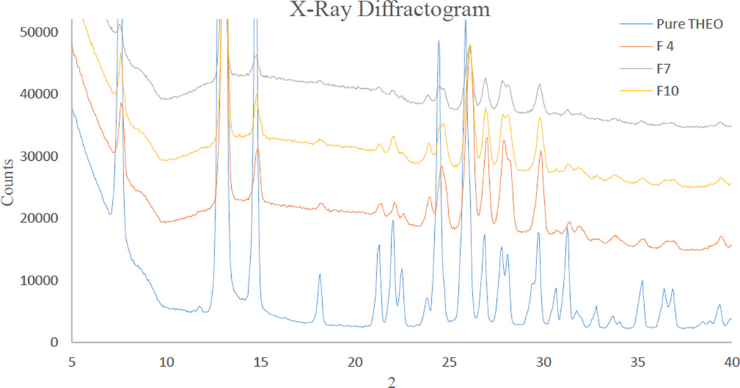
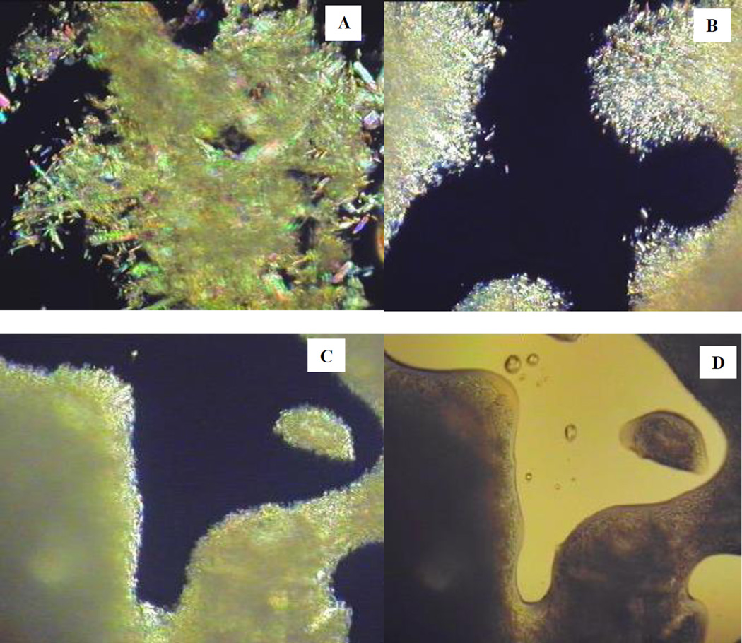
The crystalline properties of the API could not be detected by DSC because of the fact that the carriers’ degradation temperature (onset at 220 °C) was below the melting point of the API (270 °C–275 °C). However, the crystalline nature of THEO in the extrudate was confirmed by PXRD (Fig. 8). The PXRD diffractograms of the samples were homothetic and all characteristic peaks that are unique to pure THEO were presented in the diffractograms. The THEO crystals were also observed by polarized light-hot stage microscopy. At 160 °C, the polymer matrix was partly melted and showed an internal crystalline birefringence. At temperatures elevated to 200 °C, the polymer was completely melted as shown in the unpolarized light microscopy images (Fig. 7D). Under polarized light, tiny crystals of THEO could be clearly observed by the appearance of crystalline birefringence. In comparison to the crystals in the physical mixture (Fig. 7A), the THEO crystals in the extrudates were considerably smaller and narrower in their size distribution (Fig. 7B). Increasing the screw speed resulted in a further reduction of the crystal size (Fig. 7C). Similarly, melt extrusion processing imparted an effect similar to that of milling, while also preserving the polymorphic nature of the API as is evident from the PXRD diffractograms (Fig. 8).
Fig. 8.
X-Ray diffractogram of pure theophylline (THEO) crystals. Formulation 4: 40% drug loading, Formulation 7: 20% drug loading, and Formulation 10: 30% drug loading.
Fig. 7.
Polarized-light hot-stage microscopy images acquired at 200 °C. (A) Physical mixture, (B) Extrudate processed at low screw speed, (C) Extrudate processed with high screw speed, and (D) Extrudate processed with high screw speed (image acquired with unpolarized light).
Screw design significantly affects the polymorphic state of a drug. Since THEO belongs to Biopharmaceutics Classification System (BCS) class I, in this study, THEO was intended to maintain in its crystalline form for physical stability purposes. Hence, the large mixing zone of the standard screw configuration was omitted and the two smaller mixing zones were simplified. This modification decreased the shear energy imparted to the formulation and thus helped to preserve the crystalline lattice of the API. This same approach was investigated by Morott et al. who used a less aggressive screw configuration to maintain the crystalline structure of sildenafil citrate for taste-masking purposes [26].
Investigation of the Extrudate Uniformity
During processing, the monitored parameters were highly stable. At steady state, the torque and die pressure were within ±5% of the average value. The appearance and physical properties of the strand were uniform in all experimental formulations. The drug content uniformity of THEO in the extrudates at different time points in the processing varied less than 2.0% as determined by HPLC analysis.
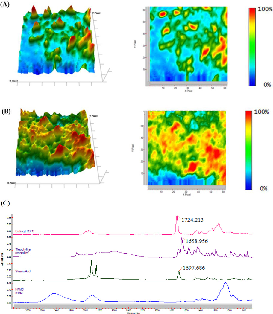
To understand the distribution of the API at the microscale level, the extrudate was characterized by FTIR chemical imaging. Random positions on the extrudate were investigated using Attenuated Total Reflectance (ATR) that directly touched the sample surface. The wavenumber of 1659 cm−1, which is unique to THEO in the formulation (Fig. 9C), was used to produce the chemical images. Fig. 9 (A and B) are representative of the infrared images taken with a Micro ATR at a 1.1-µm spatial resolution and 70 × 70-µm FOV. In all of the examined IR images, the API seems to be distributed homogeneously within the polymer matrix. The small regions with elevated THEO concentrations, which are represented by an orange or red coloration, are evenly scattered in the extrudate. The homogenous distribution of API within the matrix suggests that the drug release should be similar for the individual pellets.
Fig. 9.
The chemical images at a wavenumber of 1659 cm−1 with Ge ATR at 1.1 µm spatial resolution of the extrudate. (A) 20% drug loading, (B) 40% drug loading, and (C) Fourier Transform Infrared (FTIR) spectra of the raw materials. HPMC: hydroxypropyl methylcellulose.
The Effects of the Processing Parameters on the Buoyancy Kinetics
The pellets from all formulations floated immediately (without lag time) when placed onto the dissolution medium. The floating strength is the crucial parameter related to the buoyancy properties [12, 22]. While in the stomach, the floating dosage form may experience certain obstacles in the stomach, such as gastric emptying, stomach movement, and interactions with food stuffs. The floating strength should, therefore, be enough high to overcome these challenges. In addition, a suitable floating strength may aid the refloating of the dosage form after a temporary submergence.
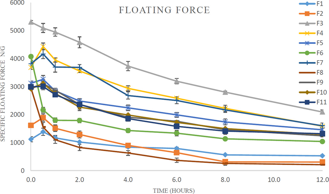
The floating ability of the pellets differed from one formulation to the other. The specific buoyancy forces varied from 1000 µN/g to 5000 µN/g (Table 4). The floating strength of certain formulations was increased after 30 min due to matrix swelling. On the other hand, the floating ability of two formulations (F6 and F8) was significantly decreased after 30 min, presumably resulting from water penetrating into the pellets’ core. The floating strength of all formulations decreased at a fairly low rate (Fig. 1). After 12 h, all pellets remained buoyant with a floating strength ranging from 200 µN/g–2000 µN/g.
Table 4.
Floating Efficiency and Drug Release Profile
| Formulation | Floating Strength (µN/g) | Drug Release (%) | ||||
|---|---|---|---|---|---|---|
| Initial | After 12 h | 1 h | 4 h | 12 h | 18 h | |
| F1 | 1119 | 529 | 0.8 | 4.1 | 16.1 | 24.0 |
| F2 | 1618 | 306 | 7.7 | 26.2 | 72.0 | 86.3 |
| F3 | 5309 | 2096 | 7.2 | 27.5 | 60.2 | 74.7 |
| F4 | 3686 | 1585 | 10.2 | 35.0 | 62.8 | 76.3 |
| F5 | 3122 | 1461 | 5.7 | 17.9 | 35.6 | 43.5 |
| F6 | 4074 | 1039 | 4.2 | 10.5 | 31.7 | 41.5 |
| F7 | 3819 | 1602 | 5.9 | 23.4 | 55.0 | 68.4 |
| F8 | 2969 | 212 | 22.3 | 52.8 | 88.8 | 96.2 |
| F9 | 2945 | 1246 | 9.3 | 25.3 | 48.9 | 66.1 |
| F10 | 2919 | 1292 | 8.6 | 22.4 | 46.1 | 63.5 |
| F11 | 2991 | 1316 | 7.2 | 23.3 | 47.5 | 64.0 |
Fig. 10.
The specific floating force profiles of the pellets (n = 3).
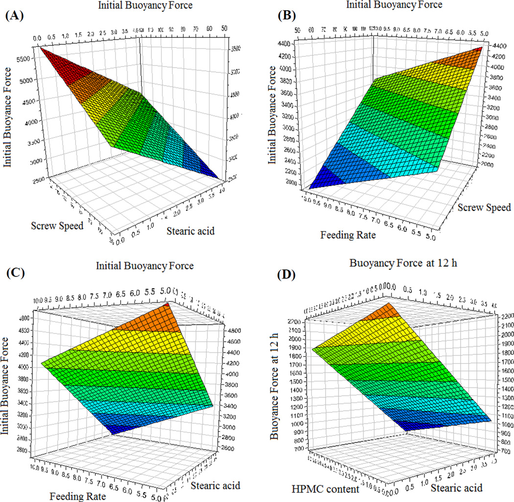
The regression equations were calculated from the experimental results using the Modde 8.0 software suite (Umetrics Inc., Sweden). The experimental data produced a suitable DoE model (p < 0.05). The goodness of fit (R2 = 0.986) and the goodness of prediction (Q2 = 0.686 > 0.5) were higher than their generally accepted critical values for screening experiments. The floating force depended on both the formulation compositions and processing parameters. The coefficients of the regression equation and the respective p values are presented in Table 5. Even though the main effects were determined using the regression results, potential interactions between the factors may have occurred. The nature of these effects on buoyancy can be better analyzed using the response surface as representatively shown in Fig. 11.
Table 5.
Statistical Analysis and Regression Coefficients of the Floating Efficiency
| Variables | Initial Floating Efficiency | Floating Efficiency at 12 h | ||
|---|---|---|---|---|
| Coefficient | P value | Coefficient | P value | |
| Model | 0.009 | 0.018 | ||
| Constant | 3142.8 | 0.000 | 1153.1 | 0.000 |
| X1 | −32.4 | 0.789 | −56.8 | 0.485 |
| X2 | 716.6 | 0.003 | 121.1 | 0.096 |
| X3 | −380.2 | 0.041 | −151.6 | 0.124 |
| X4 | 91.0 | 0.602 | −28.8 | 0.795 |
| X5 | 260.8 | 0.054 | −28.6 | 0.612 |
| X6 | −205.1 | 0.161 | −142.8 | 0.140 |
| X7 | −691.9 | 0.003 | −520.8 | 0.002 |
| R2 = 0.986, Q2 = 0.686 | R2 = 0.978, Q2 = 0.562 | |||
R2: The goodness of fit, Q2: The goodness of prediction
Fig. 11.
Representative response surfaces describing the effect of the respective variables on the floating strength of the pellets. (A) The effect of the screw speed and stearic acid content on the initial buoyancy force, (B) The effect of the screw speed and feeding rate content on the initial buoyancy force, (C) The effect of the feeding rate and stearic acid content on the initial buoyancy force, and (D) The effect of the hydroxypropyl methylcellulose (HPMC) content and stearic acid content on the buoyancy force at 12 h.
The initial floating strength is dependent primarily on the micromeritic properties of the pellets, which were found to be significantly influenced by the screw speed, feeding rate, and stearic acid content (p < 0.05). These factors also significantly influenced the porosity of the matrix. The screw speed and feeding rate had a pronounced effect on the compression of the matrix. Increasing the feeding rate compressed the matrix more, thereby decreasing the floating strength. In contrast, increasing the screw speed led to a decrease in the density of the matrix, enhancing its buoyancy. Counter to the expectations, an increase in the stearic acid content decreased the buoyancy of the matrix. This was attributed to the plasticizing effect that stearic acid imparted to the polymers, which while enhancing the processability, limited polymer chain interlocking post extrusion. This ultimately resulted in the more readily rupturing of the air pockets during the vapor expansion. The floating strength of the pellets after 12 h was most significantly dependent on the stearic acid content and screw speed. The HPMC content also negatively affected the floating force as its presence accelerated the water penetration into the pellet.
The Effect of the Variables on the Drug Release Profile
In this study, simulated gastric media (0.1 N HCl, pH 1.2) was used as the dissolution medium. During the preliminary studies, no significant differences in the drug release profile were observed by either using the USP dissolution apparatus I or II. Additionally, the rotation speed of the paddle or basket did not significantly affect the dissolution profile. This can be explained by the high solubility of THEO. The API on the surface of the pellets immediately diffused into the dissolution medium. On the other hand, the drug diffusion of the API from the core to the surface of the matrix was considerably slower and agitation-independent.
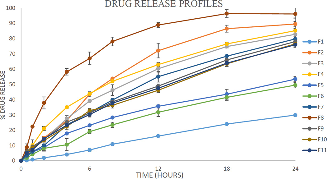
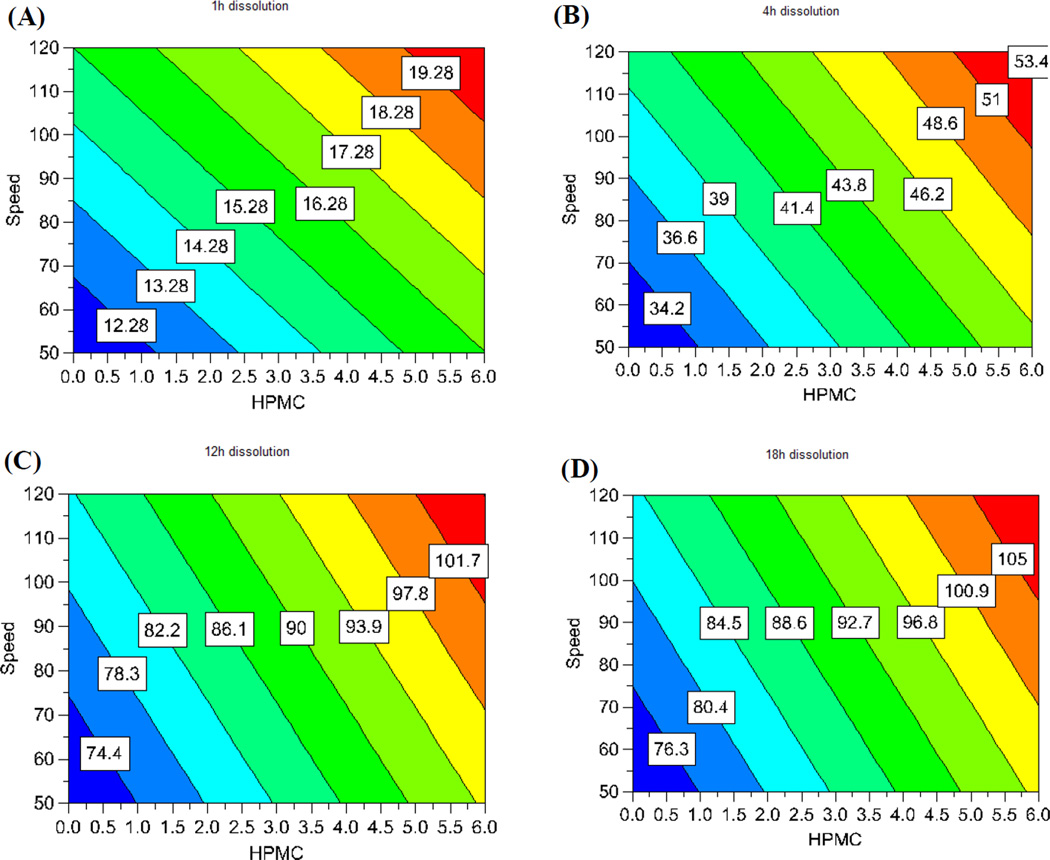
The drug release was well controlled, but varied largely between the 11 runs of the experimental design (Fig. 12 and Table 4). The independent factors had large effects on the drug release profiles. More interestingly, the drug release at the different time points measured was significantly controlled by the different factors. The model used for the correlation was dependable (p < 0.05). The goodness of fit (R2) and the goodness of prediction (Q2) of the model were both acceptable. As such, the model could be utilized to predict the outcomes of the experiments. A regression equation for drug release at the different time points measured was calculated and the resultant coefficients and their statistical parameters are listed in Table 6. The regression results indicated that the input factors affecting the drug release profiles could be visually assessed by the contour plot as shown in Fig. 13. The effect of the factors on the drug release at a certain time point could be assessed by their probability value and impact magnitude. Drug loading had the most significant effect (p < 0.05) on drug release in the first hour. This can be explained the fact that drug loading is directly related to the amount of drug exposed on the surface of the pellet, the dissolution of which is not limited by diffusion. Moreover, when drug crystals dissolve they may form pores for water to penetrate into the dosage form, and for the drug to diffuse out of. The HPMC content and screw speed also had a significant effect (p < 0.1) on drug release. Due to its hydrophilic nature, HPMC facilitates water penetration into the core of the matrix, whereas the screw speed is likely related to the structure of the strand and the vacuous pockets contained therein. The injection rate, die temperature, and stearic acid content did not demonstrate a significant effect on the drug dissolution in the first hour.
Fig. 12.
Drug release profiles of THEO from the floating pellets in 0.1N HCl (n = 3).
Table 6.
Dissolution Statistical Analysis and Coefficients of Regression
| Variables | % Drug Release 1 h |
% Drug Release 4 h |
% Drug Release 12 h |
% Drug Release 18 h |
||||
|---|---|---|---|---|---|---|---|---|
| Coefficient | P | Coefficient | P | Coefficient | P | Coefficient | P | |
| Model | 0.042 | 0.029 | 0.019 | 0.007 | ||||
| Constant | 8.10 | 0.001 | 24.40 | 0.000 | 51.34 | 0.000 | 64.05 | 0.000 |
| X1 | 1.72 | 0.149 | 3.69 | 0.138 | 4.79 | 0.152 | 4.30 | 0.103 |
| X2 | 1.81 | 0.064 | 3.72 | 0.064 | 4.84 | 0.072 | 4.92 | 0.033 |
| X3 | 1.58 | 0.174 | 2.53 | 0.262 | 0.73 | 0.789 | −0.74 | 0.715 |
| X4 | 2.00 | 0.209 | 5.37 | 0.130 | 9.15 | 0.082 | 9.66 | 0.035 |
| X5 | 2.19 | 0.040 | 3.57 | 0.071 | 2.77 | 0.216 | 1.60 | 0.310 |
| X6 | 2.23 | 0.087 | 6.14 | 0.044 | 10.70 | 0.024 | 11.36 | 0.009 |
| X7 | 0.67 | 0.363 | −1.13 | 0.446 | −0.64 | 0.741 | −1.75 | 0.274 |
| R2 = 0.959 Q2 = 0.790 |
R2 = 0.894 Q2 = 0.744 |
R2 = 0.921 Q2 = 0.665 |
R2 = 0.988 Q2 = 0.619 |
|||||
R2: The goodness of fit, Q2: The goodness of prediction
Fig. 13.
Regression contour plots showing the effect of the screw speed and HPMC content on the drug release at different time points. (A) at 1 h, (B) at 4 h, (C) at 12 h, and (D) at 18 h. HPMC: hydroxypropyl methylcellulose.
Interestingly, the impact of the independent factors on drug release changes with time. After the first hour, the HPMC content became the most significant factor affecting drug release (p < 0.05), and its effect continuously increased with time. This can be also explained by the hydrophilic nature of HPMC, which simultaneously aids the dissolution media penetration into the dosage form. Furthermore, the high-molecular weight HPMC used in this study may swell and form a gelled barrier to moderate water absorption as well as drug diffusion. Similarly, the injection rate, die temperature, and screw speed had an increasingly significant effect on drug release as the dissolution time increased. These factors have a crucial effect on the structural pattern of the matrix. In contrast, drug loading gradually loses its impact on drug release behavior over time, presumably due to the exhaustion of the externally exposed API, leading to diffusion-controlled release.
The feeding rate and stearic acid content did not have a significant effect on drug release. The fact that the main effects on the drug release profile changed with time implies that this dosage form-release profile is highly tailorable. For example, if it is desirable to increase the amount of drug release within 1 h, increasing the drug loading would be the most effective approach. However, if it is desirable to increase the drug release after 4 h, the most effective measure is to increase the HPMC content. The regression equations are a highly useful tool for the prediction of the experimental results and the formulation optimization as the range of the input variables can be determined by the contour plots as shown in Fig. 13. Therefore, DoE is among the most effective approaches to apply quality by design in drug development.
Discussion on Technique Advantages
Foamed DDS based on the mechanisms of producing low density dosage forms are safer and more predictable than those based on the gas generation within the stomach. During the lag time between ingestion and gas generation, the dosage form may be pushed through the pylorus, thereby defeating the purpose of its administration. Moreover, once it has been submerged in gastric fluid by food, buoyancy can be seriously impeded. Furthermore, the pH of the gastric fluid, which is known to vary by a large margin depending on the subject and the status of the stomach, can severely affect the floating ability of the dosage form. With its high floating strength that is maintained over a long period of time, the novel matrix used in this study is a good candidate for a dependable floating DDS.
HME, a novel systematic technology, is considerably advantageous for the scale-up process [27]. This is highly important since scale-up and process validation principles are most critical in the development of gastroretentive dosage forms [28]. In the current study, the uniform strand was extruded out at a constant rate while the torque and the die pressure were highly stable in the steady state. These are good indicators for the scalability of the process. The die pressure can also be used as an inline control for the degree of extrudate foaming. Additionally, several kinds of probes, such as near infrared (NIR) and Raman, may be used for the inline quality control of the extrudate [29,30].
The preparation of floating pellets by HME may be developed into a continuous manufacturing process by connecting the system to a die surface-cutting pelletizer creating spherical pellets [31,32]. This may be accomplished by utilizing polymer relaxation and directional gas expansion. Since the extrudate will still be in a soft state after emerging from the die, it may be spheronized by a downstream spheronization unit that is attached directly to the die. In addition, this process has the potential to be developed as a completely automatic manufacturing process based on feedback mechanisms. From the signals continuously collected from inline probe, the processing parameters can be adjusted to maintain a constant feedback signal. Thus, the product quality will be controlled and conform to the designed characteristics.
Conclusions
The results from this study demonstrate that floating pellets can be successfully prepared by HME. This novel dosage form can be used as a platform for manufacturing controlled-release DDS. The modified screw configuration was crucial to maintain the process stability, as well as to preserve the API’s crystalline form, which is presumed to enhance the physical stability of the dosage form. The internal structure, physiochemical, and micromeritic properties of the extrudate were well characterized. Based on DoE results, the floating strength of the pellets was influenced significantly by the stearic acid content, screw speed, and feed rate (p < 0.05). However after 12 h, the floating strength primarily depended on the stearic acid content. Although drug release at 1 h was controlled mostly by drug loading, the HPMC content became the most significant factor affecting drug release at later time points. This study demonstrated that the floating pellets as a platform for controlled DDS could be optimized and systematically developed for a continuous process using hot-melt extrusion technology.
Acknowledgments
This project was partially supported by Grant Number P20GM104932 from the National Institute of General Medical Sciences (NIGMS), a component of NIH. The authors would also like to thank Dr Vijayasankar Raman of the National Center for Natural Products Research, School of Pharmacy, The University of Mississippi, for his valuable assistance with the SEM imaging studies.
Footnotes
Publisher's Disclaimer: This is a PDF file of an unedited manuscript that has been accepted for publication. As a service to our customers we are providing this early version of the manuscript. The manuscript will undergo copyediting, typesetting, and review of the resulting proof before it is published in its final citable form. Please note that during the production process errors may be discovered which could affect the content, and all legal disclaimers that apply to the journal pertain.
Reference
- 1.Worsøe J, Fynne L, Gregersen T, Schlageter V, Christensen LA, Dahlerup JF, Rijkhoff NJ, Laurberg S, Krogh K. Gastric transit and small intestinal transit time and motility assessed by a magnet tracking system. BMC gastroenterology. 2011;11:145. doi: 10.1186/1471-230X-11-145. [DOI] [PMC free article] [PubMed] [Google Scholar]
- 2.Streubel A, Siepmann J, Bodmeier R. Drug delivery to the upper small intestine window using gastroretentive technologies. Current opinion in pharmacology. 2006;6:501–508. doi: 10.1016/j.coph.2006.04.007. [DOI] [PubMed] [Google Scholar]
- 3.Streubel A, Siepmann J, Bodmeier R. Gastroretentive drug delivery systems. Expert Opin Drug Deliv. 2006;3:217–233. doi: 10.1517/17425247.3.2.217. [DOI] [PubMed] [Google Scholar]
- 4.Garg R, Gupta G. Progress in controlled gastroretentive delivery systems. Tropical Journal of Pharmaceutical Research. 2008;7:1055–1066. [Google Scholar]
- 5.Pinto JF. Site-specific drug delivery systems within the gastro-intestinal tract: from the mouth to the colon. International journal of pharmaceutics. 2010;395:44–52. doi: 10.1016/j.ijpharm.2010.05.003. [DOI] [PubMed] [Google Scholar]
- 6.Özdemir N, Ordu S, Özkan Y. Studies of floating dosage forms of furosemide: in vitro and in vivo evaluations of bilayer tablet formulations. Drug development and industrial pharmacy. 2000;26:857–866. doi: 10.1081/ddc-100101309. [DOI] [PubMed] [Google Scholar]
- 7.Rahman Z, Ali M, Khar R. Design and evaluation of bilayer floating tablet of Captopril. ACTA PHARMACEUTICA-ZAGREB- 2006;56:49. [PubMed] [Google Scholar]
- 8.Baumgartner S, Kristl J, Vrečer F, Vodopivec P, Zorko B. Optimisation of floating matrix tablets and evaluation of their gastric residence time. International journal of pharmaceutics. 2000;195:125–135. doi: 10.1016/s0378-5173(99)00378-6. [DOI] [PubMed] [Google Scholar]
- 9.Iannuccelli V, Coppi G, Sansone R, Ferolla G. Air compartment multiple-unit system for prolonged gastric residence. Part II. In vivo evaluation. International journal of pharmaceutics. 1998;174:55–62. [Google Scholar]
- 10.Abouelatta SM, Aboelwafa AA, Khalil RM, El Gazayerly ON. Floating lipid beads for the improvement of bioavailability of poorly soluble basic drugs: In-vitro optimization and in-vivo performance in humans. Eur J Pharm Biopharm. 2014;89:82–92. doi: 10.1016/j.ejpb.2014.11.011. [DOI] [PubMed] [Google Scholar]
- 11.Li Z, Xu H, Li S, Li Q, Zhang W, Ye T, Yang X, Pan W. A novel gastro-floating multiparticulate system for dipyridamole (DIP) based on a porous and low-density matrix core: in vitro and in vivo evaluation. Int J Pharm. 2014;461:540–548. doi: 10.1016/j.ijpharm.2013.12.024. [DOI] [PubMed] [Google Scholar]
- 12.Singh BN, Kim KH. Floating drug delivery systems: an approach to oral controlled drug delivery via gastric retention. Journal of Controlled Release. 2000;63:235–259. doi: 10.1016/s0168-3659(99)00204-7. [DOI] [PubMed] [Google Scholar]
- 13.Iannuccelli V, Coppi G, Bernabei M, Cameroni R. Air compartment multiple-unit system for prolonged gastric residence. Part I. Formulation study. International journal of pharmaceutics. 1998;174:47–54. [Google Scholar]
- 14.Arora S, Ali J, Ahuja A, Khar RK, Baboota S. Floating drug delivery systems: a review. Aaps PharmSciTech. 2005;6:E372–E390. doi: 10.1208/pt060347. [DOI] [PMC free article] [PubMed] [Google Scholar]
- 15.Breitenbach J. Melt extrusion: from process to drug delivery technology. European Journal of Pharmaceutics and Biopharmaceutics. 2002;54:107–117. doi: 10.1016/s0939-6411(02)00061-9. [DOI] [PubMed] [Google Scholar]
- 16.Crowley MM, Zhang F, Repka MA, Thumma S, Upadhye SB, Battu SK, McGinity JW, Martin C. Pharmaceutical applications of hot-melt extrusion: part I. Drug Dev Ind Pharm. 2007;33:909–926. doi: 10.1080/03639040701498759. [DOI] [PubMed] [Google Scholar]
- 17.Pimparade MB, Morott JT, Park J-B, Kulkarni VI, Majumdar S, Murthy S, Lian Z, Pinto E, Bi V, Durig T. Development of taste masked caffeine citrate formulations utilizing hot melt extrusion technology and in vitro–in vivo evaluations. International journal of pharmaceutics. 2015;487:167–176. doi: 10.1016/j.ijpharm.2015.04.030. [DOI] [PMC free article] [PubMed] [Google Scholar]
- 18.Patil H, Tiwari RV, Upadhye SB, Vladyka RS, Repka MA. Formulation and development of pH-independent/dependent sustained release matrix tablets of ondansetron HCl by a continuous twin-screw melt granulation process. International journal of pharmaceutics. 2015 doi: 10.1016/j.ijpharm.2015.04.009. [DOI] [PubMed] [Google Scholar]
- 19.Maniruzzaman M, Boateng JS, Snowden MJ, Douroumis D. A review of hot-melt extrusion: process technology to pharmaceutical products. ISRN Pharm. 2012;2012:436763. doi: 10.5402/2012/436763. [DOI] [PMC free article] [PubMed] [Google Scholar]
- 20.Repka MA, Battu SK, Upadhye SB, Thumma S, Crowley MM, Zhang F, Martin C, McGinity JW. Pharmaceutical applications of hot-melt extrusion: Part II. Drug Dev Ind Pharm. 2007;33:1043–1057. doi: 10.1080/03639040701525627. [DOI] [PubMed] [Google Scholar]
- 21.Anthony Armstrong N. Pharmaceutical Experiment Design and Interpretation. (2nd Edition) 2006:121–122. [Google Scholar]
- 22.Timmermans J, Moes A. How well do floating dosage forms float? International journal of pharmaceutics. 1990;62:207–216. [Google Scholar]
- 23.Eisenacher F, Garbacz G, Mader K. Physiological relevant in vitro evaluation of polymer coats for gastroretentive floating tablets. Eur J Pharm Biopharm. 2014;88:778–786. doi: 10.1016/j.ejpb.2014.07.009. [DOI] [PubMed] [Google Scholar]
- 24.Zhai H, Jones DS, McCoy CP, Madi AM, Tian Y, Andrews GP. Gastroretentive extended-release floating granules prepared using a novel fluidized hot melt granulation (FHMG) technique. Mol Pharm. 2014;11:3471–3483. doi: 10.1021/mp500242q. [DOI] [PubMed] [Google Scholar]
- 25.Brunauer S, Emmett PH, Teller E. Adsorption of gases in multimolecular layers. Journal of the American Chemical Society. 1938;60:309–319. [Google Scholar]
- 26.Morott JT, Pimparade M, Park JB, Worley CP, Majumdar S, Lian Z, Pinto E, Bi Y, Durig T, Repka MA. The Effects of Screw Configuration and Polymeric Carriers on Hot-Melt Extruded Taste-Masked Formulations Incorporated into Orally Disintegrating Tablets. Journal of pharmaceutical sciences. 2015;104:124–134. doi: 10.1002/jps.24262. [DOI] [PMC free article] [PubMed] [Google Scholar]
- 27.Patil H, Tiwari RV, Repka MA. Hot-Melt Extrusion: from Theory to Application in Pharmaceutical Formulation. AAPS PharmSciTech. 2015 doi: 10.1208/s12249-015-0360-7. [DOI] [PMC free article] [PubMed] [Google Scholar]
- 28.Pawar VK, Kansal S, Asthana S, Chourasia MK. Industrial perspective of gastroretentive drug delivery systems: physicochemical, biopharmaceutical, technological and regulatory consideration. Expert opinion on drug delivery. 2012;9:551–565. doi: 10.1517/17425247.2012.677431. [DOI] [PubMed] [Google Scholar]
- 29.Wahl PR, Treffer D, Mohr S, Roblegg E, Koscher G, Khinast JG. Inline monitoring and a PAT strategy for pharmaceutical hot melt extrusion. International journal of pharmaceutics. 2013;455:159–168. doi: 10.1016/j.ijpharm.2013.07.044. [DOI] [PubMed] [Google Scholar]
- 30.Saerens L, Dierickx L, Lenain B, Vervaet C, Remon JP, De Beer T. Raman spectroscopy for the in-line polymer–drug quantification and solid state characterization during a pharmaceutical hot-melt extrusion process. European Journal of Pharmaceutics and Biopharmaceutics. 2011;77:158–163. doi: 10.1016/j.ejpb.2010.09.015. [DOI] [PubMed] [Google Scholar]
- 31.Young CR, Koleng JJ, McGinity JW. Production of spherical pellets by a hot-melt extrusion and spheronization process. International journal of pharmaceutics. 2002;242:87–92. doi: 10.1016/s0378-5173(02)00152-7. [DOI] [PubMed] [Google Scholar]
- 32.Young CR, Dietzsch C, McGinity JW. Compression of controlled-release pellets produced by a hot-melt extrusion and spheronization process. Pharmaceutical development and technology. 2005;10:133–139. doi: 10.1081/pdt-49695. [DOI] [PubMed] [Google Scholar]


