Abstract
The limits to optical resolution and the challenge of identifying specific protein populations in transmission electron microscopy have been obstacles in cell biology. Many phenomena cannot be explained by in vitro analysis in simplified systems and need additional structural information in situ, particularly in the range between 1 nm and 0.1 µm, in order to be fully understood. Here, electron spectroscopic imaging, a transmission electron microscopy technique that allows simultaneous mapping of the distribution of proteins and nucleic acids, and an expression tag, miniSOG, are combined to study the structure and organization of DNA double-strand break repair foci.
Keywords: Molecular Biology, Issue 103, Electron spectroscopic imaging (ESI), chromatin structure, DNA-repair, electron microscopy, miniSOG, correlative microscopy
Introduction
Despite the significant advancements in light microscopy over recent years1, cell-biologists still suffer from a gap in resolution. This limits understanding of the structure-function relationships in fundamental cellular processes that involve the coordinated interplay between macromolecular complexes (e.g., in chromatin remodelling, DNA repair, RNA transcription and DNA replication). Although transmission electron microscopes (TEM)s provide the required resolution, it has been challenging to define these processes structurally because of the inability to label specific proteins while also being able to determine the biochemical composition of the visualized structures. In the absence of internal membranes to help differentiate nuclear structures, the nucleus has been particularly challenging. Electron spectroscopic imaging (ESI) solves some of these limitations by allowing the simultaneous detection and differentiation of DNA, RNA, and protein-based nuclear structures2-5.
Electron spectroscopic imaging:
In order to map elemental distributions at high sensitivity and resolution in the electron microscope, one can use an imaging spectrometer that selects electrons that have been inelastically scattered through interactions with inner shell electrons of an element in the specimen6. Because element-specific amounts of energy are lost as a consequence of ionization of atoms in the specimen, these electrons can be separated and visualized using a spectrometer that is attached to the electron microscope. Thus, analysis of the spectrum of the electrons that have interacted with the specimen reveals qualitative and quantitative information about the elemental composition of the sample7. Electrons that do not lose energy when passing through the specimen are found in the “zero-loss peak” of the electron energy loss spectrum. The abundance of these electrons is related to the mass, density and thickness of the specimen and is comprised of electrons that pass through the specimen without colliding with the specimen or losing energy during passage through the specimen. This information can be useful for absolute quantification of the numbers of atoms of a specific element present in the specimen8.
Since biological samples consist mostly of light elements that poorly deflect the electrons in the incident beam of the TEM, staining methods using heavy metal salts have to be applied in order to generate contrast in the sample. The lack of specificity of most of these contrasting agents and the inability to visualize more than one stain where specificity is possible has limited the value of conventional electron microscopy in the study of the nucleus. ESI has significant advantages over conventional TEM, particularly for the study of structures of the cell nucleus. It is possible to exploit the phosphorus-rich nature of DNA- and RNA-containing macromolecular complexes to distinguish nucleoprotein complexes from protein complexes and to resolve different nucleoprotein complexes based on their density of nucleic acids. The remaining biological material can be imaged based on its abundance of nitrogen. Mapping just these two elements and analysis of their distribution and relative abundance within different anatomical structures provides us with a lot of information about the nucleus. For example, it is easy to identify chromatin and the ribosomes in the map representing phosphorus abundance. The interchromatin space, nuclear pore complexes, and nuclear bodies, on the other hand, can be easily detected in the nitrogen map image.
Mini singlet oxygen generator system (miniSOG)
While ESI represents a powerful technique to study in situ chromatin structure because it takes advantage of the characteristic ratios in elemental composition between phosphorus and nitrogen, the elemental composition cannot normally be used to discriminate between different populations of protein complexes. Antibodies labeled with small gold particles in the nanometer range have been widely used to map the location of individual molecules. Since the gold particle is usually attached to a secondary antibody, it will appear within a circumference of approximately 20 nm around the epitope detected by the primary antibody. In post-embedding samples, antibodies can only detect the epitopes that are exposed at the surface of the sections. While it is possible to prove the presence of an antigen and relate it to a certain anatomical structure of the cell, the information that is obtained is incomplete, since most of the epitopes are obscured by resin. Pre-embedding techniques, which use similar protocols to those used for fluorescence microscopy, allow access to antigens throughout the entire depth of the sample but the permeabilization steps that are required to allow the antibody to penetrate the cell typically require removal of lipid membranes and remove components that cannot be fixed by aldehydes. Moreover, the preferred aldehyde fixative for ultrastructure preservation, glutaraldehyde, commonly destroys epitopes and, consequently, paraformaldehyde is typically required. This is less effective at protein-protein crosslinking. Another disadvantage of antibodies that are labeled with a gold nanoparticle is that gold is a very electron-dense material that creates a strong contrast that can obscure interesting structural details of the sample, which has weaker contrast.
The emergence of the green fluorescent protein (GFP) as an expressed protein tag has transformed the use of fluorescence microscopy to answer questions in cell biology. Tagging a protein with a small fluorescent domain allows mapping of its distribution in vivo without the need for permeabilization procedures that can alter the structure. In order to translate the elegant principle of using protein tags to map protein distributions in a cell to electron microscopy, a system was needed that is able to produce a signal close to the structure of interest and generate contrast in the TEM. Polymerized diaminobenzidine is a stain that is often used in histology to detect antibody binding. This stain is usually deposited using horseradish peroxidase (HRP) conjugated to a secondary antibody. Although the reaction produces a reliable result, HRP is not catalytically active in the cytosol of cells9. The reaction products of HRP can also diffuse away from the site of generation so that their resolution is worse than the nanogold method10. In order to bypass these problems, the FlAsH/ReAsH system was developed11. It consists of recombinant fusion proteins that possess a tetracysteine motif. This motif allows binding of a biarsenic fluorophore. When excited, the bound FlAsH or ReAsH is able to generate the highly reactive singlet oxygen and thus photoconvert diaminobenzidine (DAB) into a polymer that precipitates immediately at the site of the tagged proteins. The DAB polymer can be stained with osmium tetroxide, which is electron dense and thus can be used to map the distribution of the recombinant fusion protein in the TEM.
In 2011, Shu et al.10 presented the miniSOG system, which consists of a small 106 amino acids fusion tag derived from a flavoprotein of Arabidopsis that is fluorescent and able to create many singlet oxygen radicals when excited with 448 nm blue light. Those singlet oxygen radicals can be used to photo-oxidize diaminobenzidine to form polymers on and near the surface of the tagged protein, which is considerably closer than immunogold labeled antibodies11. While the FlAsH/ReAsH system requires bringing the fluorochrome and the diaminobenzidine into the cells before doing the photoconversion, the miniSOG system only requires diaminobenzidine and light and in addition is about twice as effective at polymerizing diaminobenzidine. Here, miniSOG is employed in combination with ESI in order to map the ultrastructure of DNA repair foci.
DNA repair foci (DRF)
Unrepaired DNA double strand breaks pose a serious threat to the cell since they can lead to translocations and loss of genetic information. In turn, this can lead to senescence, cancer, and cell death. Many proteins that are involved in DNA double strand break repair accumulate in foci that assemble around a DNA double strand break12-14. Although their function is not known, they represent the site in the nucleus that contains the DNA double strand break and is the site of DNA double strand break repair.
DNA repair foci (DRF) have been characterized by fluorescence microscopy and they serve as biomarkers for DNA damage12,15. They are massive relative to the size of the double-strand break and were considered relatively homogeneous until recent super-resolution microscopy studies revealed some evidence of sub-compartmentalization of molecules within each focus16. In order to understand how these sites are organized, it is necessary to visualize all of the underlying biological structures relative to each other. This cannot be achieved by fluorescence microscopy but is possible through electron microscopy17,18. Here, a method is described that combines electron spectroscopic imaging with the miniSOG method to illustrate the potential of this combined approach to explore the ultrastructure of DNA double-strand break repair.
Protocol
1. Generation of miniSOG Cell-lines
Grow U2OS (human osteosarcoma) cells in a 35 mm dish containing 2 ml of low glucose Dulbecco’s modified Eagle’s medium (DMEM) that is supplemented with 10% foetal bovine serum (FBS) at 37 °C in a humidified incubator with 5% CO2 atmosphere.
Transfect the cells when they are 80% confluent by lipofection with purified transfection quality (A269/280 ratio 1.8-2.0) plasmid constructs containing the sequences for miniSOG and mCherry tagged repair proteins according to the protocol of the manufacturer of the transfection reagent19. The miniSOG expression plasmids can be ordered from the Tsien-Lab: http://www.tsienlab.ucsd.edu/Samples.htm
Sort the cells expressing the recombinant protein with the miniSOG and mCherry tag by fluorescence activated cell sorting two days post transfection. Collect cells with intermediate fluorescence intensity in order to avoid cells that are overexpressing20.
Culture the positive cells on a 10 cm dish in 10 ml of DMEM medium that is supplemented with 10 % FBS and 0.6 µg/ml of the selection agent G418 (Geneticin).
After visible colonies have emerged on the plates, screen for mCherry positive colonies using an inverted fluorescence microscope and draw circles around them (onto the bottom of the plate) with a permanent marker. Use a low magnification air objective lens (e.g., 10x) and pick clones using sterile technique by carefully scratching the colonies off and slowly sucking them into a sterile 1,000 µl pipette tip.
Expand the selected colonies and freeze parts of them down using the growth medium described in step 1.1 supplemented with 10% dimethyl sulphoxide. Test the cells for DRF formation by growing them on sterile 18 x 18 mm2 cover slips and exposing them to 2 Gy of radiation. The irradiated cells stably expressing a miniSOG mCherry tagged repair protein must show the typical focal pattern characteristic of DSBs when visualized with a fluorescence microscope using a filter-set for imaging mCherry.
2. Cell Culture
Culture U2OS cells stably expressing the miniSOG and mCherry tagged repair proteins under the conditions outlined in step 1.1. Grow cells to 80% confluency in a 35 mm diameter glass bottom dish containing 2 ml of DMEM. Make sure that the glue that attaches the cover slip to the plastic and the used plastic is resistant to aqueous and alcoholic solutions and resistant to the resin used!
Before conducting the experiment, outline a small area of approximately 1 mm2 that contains cells expressing the ectopic proteins by scratching with a sterile diamond pen using a fluorescence microscope to identify the region of interest. Alternatively use a glass bottom dish that contains a coverslip with a pre-etched grid system built into the coverslip. NOTE: If using high quality correlative microscopy combining ESI and fluorescence microscopic pictures21, make sure that the thickness of the coverslip is compatible with oil immersion objectives. It should have the thickness No. 1.5 (0.16-0.18 mm). Choose an area close to the center of the dish for the region to be examined in the TEM in order to avoid problems with polymerization of the resin that may occur near the edges (see point 4.10-4.13).
3. DNA Damage Induction
Irradiate the cells with gamma radiation, use a radiomimetic drug, or induce the damage by laser micro irradiation on a confocal microscope (e.g., as described in18,22 or 23).
In this example, irradiate the cells with 2 and 6 Gy of gamma irradiation in a cesium-137 radiation source or laser microirradiate using the 405 nm solid state laser of a confocal microscope after sensitizing the cells for 20 min with 0.5 µg/ml Hoechst.
4. Sample Preparation
Fix the cells with 1 ml of 4% paraformaldehyde CAUTION in 0.1 M sodium cacodylate buffer or in 0.1 M phosphate buffer pH 7.4 for 30 min at RT in the dark. CAUTION: Paraformaldehyde and sodium cacodylate are toxic! Wear gloves and dispose the toxic substances adequately.
Wash the cells twice with 4 ml of 0.1 M sodium cacodylate buffer pH 7.4 or phosphate buffer pH 7.4.
Treat the fixed cells with 2 ml of 50 mM glycine, 5 mM aminotriazole and 10 mM potassium cyanide CAUTION in 0.1 M sodium cacodylate buffer or 0.1 M phosphate buffer (pH 7.4) (check the pH!) for 30 min in order to block unreacted aldehyde groups and to suppress the reactive oxygen species generated by heme groups, which can increase the background. CAUTION: Potassium cyanide is extremely toxic! Wear gloves, work under a hood and dispose the toxic substances adequately. The reaction is very sensitive to pH so it is important that the pH verified and accurate.
Record the area that was selected in step 2.2 in 2D or 3D on an inverted fluorescence microscope, if correlative microscopy is desired.
Prepare a 1 mg/ml diaminobenzidine hydrochloride CAUTION solution by placing a 10 mg diaminobenzidine hydrochloride tablet into a 2 ml microcentrifuge tube. Add 980 µl of distilled H2O and 20 µl of concentrated hydrochloric acid (11.65 M) and mix until the solution is light brown and translucent. Dilute this solution in 0.1 M phosphate or 0.1 M sodium cacodylate buffer to a final concentration of 1 mg/ml while adjusting the pH with sodium hydroxide to a pH between 7.0 and 7.6 (pH 7.4 is recommended). CAUTION: Diaminobenzidine is toxic! Wear gloves and dispose the toxic substances adequately.
For photooxidation, replace the buffer with 2 ml of a 1 mg/ml diaminobenzidine hydrochloride solution in 0.1 M sodium cacodylate buffer or phosphate buffer. Protect this solution from light and cool it down on ice to 4 oC in order to increase the solubility of oxygen. Saturate the solution with oxygen by bubbling oxygen through the solution (use a hose that is inserted into the solution and connected to an oxygen bottle). Check the pH again and adjust if necessary. NOTE: It is crucial for the photooxidation reaction that the pH is between pH 7.0 and pH 7.6.
Mount the dish with the fixed cells carefully onto an inverted fluorescence microscope equipped with a 40x oil immersion objective lens and move it to the area of interest. Excite the miniSOG tag with blue light by using filter cubes for GFP or CFP. MiniSOG has an excitation maximum at 448 nm with a shoulder at 473 nm10.
Continue with the illumination even after the green miniSOG fluorescence has completely disappeared and until the brown photo-oxidation product of the polymerized diaminobenzidine emerges in the transmitted light channel. When the oxidation product is visible in most of the cells, turn off the fluorescence illumination to stop the photo-oxidation. NOTE: Photo-oxidation can take up to several minutes depending on the objective lens, filter transmission wavelengths and efficiency, and the illumination source.
Postfix the cells with 1 ml of 2% glutaraldehyde in 0.1 M sodium cacodylate pH 7.4 buffer or phosphate buffer pH 7.4 for 30 min.
Fix the membranes of the cells with 0.1%-0.5% osmium tetroxide for 20 min in 0.1 M sodium cacodylate buffer pH 7.4 or in 0.1 M phosphate buffer pH 7.4. NOTE: It is recommended to use the lowest possible concentration of osmium tetroxide required to stabilize the membranes. Since the polymerized DAB precipitates have a high density of nitrogen, which can be detected directly by ESI, a strong osmium staining is not necessary to identify the miniSOG-tagged protein and might be detrimental to the ESI. Osmium tetroxide is very toxic! Work in a fume hood and dispose the toxic waste adequately.
Dehydrate, the cells through an ethanol series using 30%, 50%, 70%, 90%, 98% 100% ethanol steps (each 5 min). Subsequently, incubate the cells in a 1:1 mix of 100% ethanol and acrylic resin (LR White) and put the dish onto a shaker for 4 hr to facilitate infiltration into the cells before incubating the cells for at least another 4 hr in 100% acrylic resin (LR White).
In order to polymerize the resin, cut off the lid of a labeled 2 ml microcentrifuge tube with a razor blade and coat the rim with acrylic resin accelerator. Make sure that the accelerator only covers the rim and does not flow into the tube. Subsequently, carefully fill the tube approximately two-thirds with LR White resin using a Pasteur pipette. Take care that the resin does not get into contact with the accelerator on the rim!
Remove the resin that infiltrated the cells in the dish and place the dish upside down onto the upright standing microcentrifuge tube so that the width of the tube almost completely fills up the glass covered observation window of the dish.
Wait 1 to 2 min for the accelerator to seal the tube and the coverslip, then invert the tube so that the resin in the tube now covers the cells.
Place the dish with the tube into an oven at 60 °C and cure it for 12 hr.
When the block is cured, remove the dish with the attached resin-filled microcentrifuge tube from the oven and separate the microcentrifuge tube from the dish. Facilitate separation by freeze-thaw cycles in liquid nitrogen and hot water.
Discard the glass bottom dish and carefully cut open the microcentrifuge tube with a razor blade in order to remove the block.
Label the block with a permanent marker.
Use a razor blade to trim the block so that nothing but the 1 mm2 region that contains the area previously marked with the diamond or tungsten pen (or contains the area with the cells of interest) remains.
Mount the block in an ultramicrotome, trim the block with a trimming knife and cut ultra-thin sections of approximately 50 nm using a diamond knife.
Pick up the sections on high-transmission 300 mesh grids. These grids have very small grid bars and thus cover fewer cells in the area of interest.
Coat the sections on the grids with about 0.2-0.4 nm of carbon using a carbon coater to help stabilize them under the electron beam of the TEM.
5. Electron Microscopy
Load the grids into a TEM that is equipped with an energy filter. After tuning the microscope and the energy filter according to the manufacturer’s instructions, inspect the cells on the sections in the low magnification mode (normal transmission) and compare them to fluorescence data when appropriate (obtained in step 4.4).
Once a nucleus with interesting features (DNA damage track or DNA repair foci) is found, switch to the energy filtering mode and record a thickness map. NOTE: This procedure includes the recording of a zero-loss and an unfiltered image. Thicknesses up to 0.3 mean free path (30% of the electrons of the incident beam gets scattered by the sample) are thin enough to generate good elemental maps.
Record ratio maps of the elements phosphorus and nitrogen using the software that controls the energy filter of the microscope used. Record the phosphorus map post edge images at 175 eV energy loss with a slit width of 20 eV and pre-edge images at 120 eV energy loss, also with a slit width of 20 eV. For the nitrogen maps, record post edge images at 447 eV with a slit width of 35 eV and pre-edge images at 358 eV, also with a slit width of 35 eV. NOTE: Since the content of the imaged elements (phosphorus and nitrogen) is relatively low (approx. 1%), choose “Ratio Image” (qualitative elemental map) over the “3 window method” (quantitate elemental map) in order to generate images with a better signal to noise ratio.
6. Image Processing
Open the elemental ratio maps in an image processing software that can handle the file format of the acquired pictures (e.g., Digital Micrograph). Copy the nitrogen map into the red channel and the phosphorus map into the green channel of an RGB image, then superimpose and align the maps.
Export the composite image as a tagged image file format (TIFF) file. Open the image in an image processing software that can use layers (e.g., Photoshop).
Adjust the dynamic range of each channel by rescaling the minimum and maximum values in the image to an 8-bit data set (0 to 255).
Subtract the phosphorus content from the nitrogen map (using the “Layers” window) in order to generate a qualitative map that shows the distribution of protein.
Convert the maps of the nucleic acid (phosphorus) and the protein (nitrogen) created in the previous step into “indexed color” and create a yellow lookup table in the CMYK color space for the map showing the nucleic acid distribution and a cyan lookup table to show the non-nucleoprotein map. The colors are chosen to generate maximum contrast between the two elemental maps.
Create a new image and import the maps showing the distributions of phosphorus and protein as different layers. Use the “screen” transparency mode in order to see both layers superimposed on each other.
Open the zero-loss image acquired in step 5.2. This image represents an image of the recorded area that looks like a conventional TEM image but only contains the electrons that have passed through the specimen without colliding with the specimen. Export this image as a TIFF image.
Open the exported zero loss image in a photo editor and copy it into the uppermost layer of the image showing the elemental map. Align the image using the “screen” transparency mode.
Optionally threshold the zero-loss image to segment the signal that originates from the miniSOG. Add the resulting image as a separate layer as described above.
Representative Results
ESI
Comparing the ESI images of the nucleus (Figure 1) with the conventional TEM images (e.g., Figure 7-1) reveals a dramatic increase in anatomical structures that can be easily distinguished. The chromatin ridges appear in yellow and it is quite easy to identify the chromocenters in mouse cells. Nucleoli can easily be distinguished from chromatin by their round structure and different color, since the pre-assembled ribosomes already contain high amounts of protein, which is rich in nitrogen, in addition to the RNA, which is rich in phosphorus. The peripheral chromatin resides as a thin layer on the border of the nucleus and nuclear pores can be seen as nitrogen-rich structures that interrupt the peripheral chromatin. Often the lamina can be seen as a very thin blue layer outside of the peripheral chromatin. In the cytoplasm, many small particles rich in phosphorus can be seen. These can be identified as ribosomes based on their size, abundance and location outside the nucleus. The interchromatin space can be seen as the protein-rich area located between the chromatin. This contains nuclear bodies and areas rich in small yellow signals, such as ribonucleoprotein particles and clusters of ribonucleoprotein granules (Figure 2). The latter are termed interchromatin granule clusters and are characteristically enriched in proteins required for pre-mRNA splicing. Figure 1B, C and D illustrate the appearance of other known structures such as mitotic chromosomes, centrosomes, mitochondria and centromeres. In Figure 2, the steps used to generate colored composite pictures from the raw elemental ratio maps are summarized. Merging the phosphorus map (green) and the nitrogen map (red) in RGB color space (upper row) allows a better assessment of the amounts of those elements in the sample. However, subtracting the phosphorus signal to deplete the contribution of nucleic acid-containing structures from the nitrogen map to yield the protein map (cyan) and merging it with the phosphorus map (yellow) in CYMK color space provides a more distinct visual representation of nucleoprotein and non-nucleoprotein (lower row). This allows the data to be more easily interpreted by individuals unfamiliar with the technology.
Laser microirradiated cells expressing MDC1, 53BP1 and Rad52
Due to the user-defined size, shape and location of the laser damage tracks, the region of DAB deposition in the laser microirradiated cells are very easy to find in the TEM when using the miniSOG system. Pictures taken in low magnification transmission mode (i.e., conventional brightfield TEM) reveal the characteristic damage tracks and can be compared with data that was recorded with a fluorescence microscope prior to embedding. This is especially useful if correlative microscopy is intended, since it allows easy identification and relocation of single nuclei. (Figure 2-4).
The first example (Figure 3) shows an U2OS cell line stably expressing MDC1 miniSOG-mCherry. In a laser microirradiation experiment, the recruitment of the MDC1 containing the miniSOG and mChrerry tags was very similar to GFP-tagged versions of this protein (data not shown). Fixing the cells 1 hr after DNA damage induction and preparing the sample for the TEM, the MDC1 damage tracks were easily identified in the ultra-thin sections in normal TEM mode as dark stripes across the nuclei, which corresponded very well to the fluorescence data (Figure 3-5). When looking at the distribution of the protein, a clear increase in nitrogen signal could be observed at the laser-damaged sites. It has to be pointed out here that this is primarily caused by the polymerized diaminobenzidine, which is rich in nitrogen and amplifies the signal of the miniSOG tagged repair protein, rather than solely through the accumulation of repair proteins in the damage track. Comparing the chromatin structure in the rest of the nucleus with the structure in the damage tracks shows a clear difference. The damaged chromatin (that is shown within the dashed lines in Figure 3) appears more decondensed in contrast to the non-irradiated chromatin, which occurs in thick ridges in the nucleoplasm. Within the damage tracks, nuclear bodies (200-300 nm) (highlighted by arrows in Figure 3 II2, IIb, IIc and IIIa) that are rich in MDC1-miniSOG protein but free from nucleic acid could also be observed. It would be very challenging to define these nuclear bodies as chromatin-free structures without this technique. It also suggests an additional level of complexity to damage sites that is not predicted by the known biochemistry of MDC1.
Looking at the damage tracks of 53BP1 (Figure 4) that were created using the same conditions as the previously described damage in MDC1-transfected cells, very similar results can be observed. The signal that was produced by the photo-oxidation of the miniSOG was crowded and filled up the space between the folds of the chromatin. Heavily stained nuclear bodies could also be observed (highlighted by an arrow in Figure 4 D,E,F).
From experiments with Rad52-GFP constructs, it is known that Rad52 will form small bright microcompartements24 along a laser-induced damage track. Due to the resolution limit of conventional light microscopes, it has been unclear how large these structures really are and how they relate to the damaged DNA. Looking at the TEM image of laser-irradiated U2OS nuclei constitutively expressing Rad52-miniSOG-mCherry, the size of these bodies were measured to be in average (150-250 nm). It is even more surprising to look at these foci with ESI. In contrast to the previous examples, the Rad52-miniSOG-mCherry foci seem to be organized quite differently along the damage track and appear to be compact nuclear body-like structures that are comprised of protein and have no detectable nucleic acids within their interior. Based on looking at the nucleic-acid/protein relationship in the damaged areas obtained with our combined miniSOG and ESI approach, we suggest that the DNA repair may take place at the surface of the foci rather than in the interior.
The lower image in Figure 5 shows results similar to Figure 3-III. The chromatin in the damaged area seems to be more decondensed compared to the chromatin in the non-irradiated areas (see area outlined by red dashes).
Gamma irradiated cells
While laser micro-irradiation is a convenient tool to quickly test proteins that contain a fluorescent tag for recruitment to sites of DNA lesions, it creates large amounts of complex damage (double strand breaks, single strand breaks, base damage, and cyclopyrimidine dimers)25. In order to study the compartments that form around DNA double strand breaks more directly, we examined DRFs that form around individual DSBs by exposing cells to gamma irradiation.
U2OS cells that stably express 53BP1-miniSOG-mCherry were exposed to 2 Gy of gamma irradiation and fixed half an hour after the irradiation. The characteristic pattern of large foci distributed throughout the nucleoplasm could be observed (Figure 6Ia). After photo-oxidation of diaminobenzidine, dark spots emerging at the positions where the fluorescent mCherry signals were located in fluorescence micrographs could be seen in the electron micrographs (Figure 6Ib and c). These spots could be correlated to TEM images that were taken at low magnification (Figure 6Id and e). The ESI images of these foci, which appeared to be about 1-1.5 µm in diameter, showed an interesting structure. Thin strands of chromatin seemed to be interspersed with 53BP1 protein of approximately twice the thickness.
In other experiments, the cells were exposed to a higher amount of radiation and fixed at later time points (after 3 hr and 6 hr, respectively) in order to generate larger foci and facilitate locating them in ultra-thin sections (Figure 7). Because we are able to separately map nucleoprotein and protein, ESI reveals that the structure of the foci appear to reorganize over time. The relative amount of 53BP1 protein in the focus appears to increase while the chromatin takes a more peripheral position.
Since 53BP1 foci also appear in non-irradiated cells as “cryptic foci” in G1 cells at sites of under-replicated DNA26,27, those foci were also imaged. These cryptic foci seem to harbour high amounts of protein relative to the radiation induced foci and show an interesting regular structure of chromatin.
Thus, visualizing DNA repair foci constituents using the miniSOG method helps to identify regions of DNA damage and to map the distribution of the tagged repair protein relative to the chromatin.
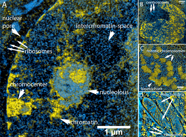 Figure 1. Overview of structures that can be observed in an ESI image
Please click here to view a larger version of this figure.
(A) ESI image of a mouse embryonic fibroblast. Chromatin ridges (yellow) are surrounded by nucleoplasm (cyan) filling up the interchromatin space. The nucleus is surrounded by peripheral heterochromatin and chromocenters (lower left) that are interrupted by nuclear pore complexes (cyan). The nucleoli can be clearly separated by their color. This is due to the fact that amount of protein relative to nucleic acid is higher in the nucleolar structure than it is in chromatin. Outside the nucleus, mitochondria and ribosomes (rich in nucleic acid) can be easily identified.
(B) Image of a nucleus and the centrosomes (see arrows), which can be seen as hollow protein-rich particles in the upper left of the image.
(C) Cross section through a metaphase plate. The highly condensed metaphase chromosomes have aligned to a disk that spans from the upper left corner to the lower left corner. High concentrations of nitrogen are visible at the surface of some chromosomes. These areas are the kinetochores (see arrows).
D: Parts of mitochondria (see upper arrows) in the cytoplasm surrounded by ribosomes (small yellow spots – see lower arrows). The inner membrane of the mitochondria with its typical invaginations (cristae) is visible.
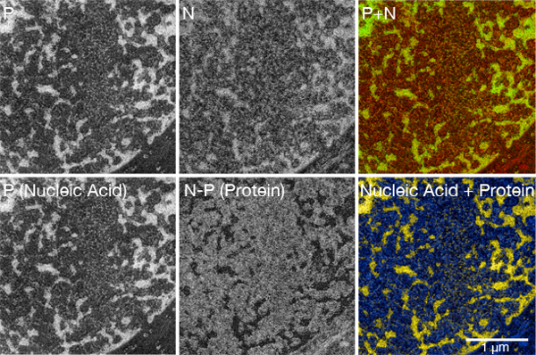 Figure 2. Creation of a multi-color ESI picture
(Upper row) The first two pictures in the row show the ratio maps of phosphorus and nitrogen. The last picture in the upper row shows these elemental maps superimposed in the RGB color space. Yellow structures represent nucleoproteins, reflecting the presence of both phosphorus and nitrogen.
(Lower row) The first picture shows the phosphorus map, which primarily reveals the distribution of nucleic acid in the sample. The middle picture shows the distribution of nucleic acid-depleted/negative structures. It was calculated by subtracting the phosphorus map from the nitrogen map. The lower right picture shows a merge of the nucleic acid map and the protein map in the subtractive color space. This color composite should be used to assist in the identification of individual structures and to classify them as nucleoprotein or not nucleoprotein. The quantitative information on the phosphorus and nitrogen abundance should be gathered visually from the net phosphorus and net nitrogen greyscale maps or from composites generated by using additive colors, such as in the top row.
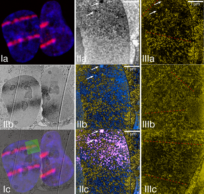 Figure 3. Laser micro irradiation of U2OS cells stably expressing MDC1-miniSOG-mCherry.
Please click here to view a larger version of this figure.
(I) The upper image shows laser microirradiated cells that were fixed approximately 30 min after irradiation. The blue color shows the nucleus of a Hoechst-sensitized cell. The red signal shows the distribution of MDC1-miniSOG-mCherry following its recruitment to the sites of DNA damage. Ib shows a low magnification conventional TEM image taken from the same cells that are shown in Ia. Ic shows an overlay of Ia and Ib. This example of correlative microscopy shows how good the match between the fluorescence signal and the miniSOG-generated signal is.
(II) The area, highlighted by a green square in Ic was magnified and shown in normal transmission mode (IIa) and ESI (IIb). IIc shows an overlay of the ESI image with the signal of the damage track. The damage track signal was obtained by thresholding the upper image.
(III) Examples of the structure of laser micro-irradiated chromatin and chromatin outside the laser-damaged area.
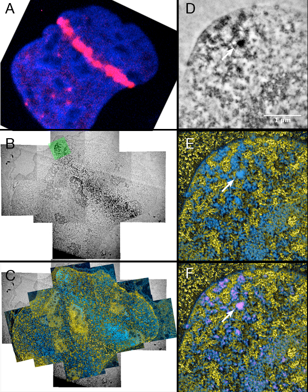 Figure 4.
Laser micro irradiation of cells stably expressing 53BP1-miniSOG-mCherry.
Please click here to view a larger version of this figure.
Left column: (A) Fluorescence, (B) Conventional TEM and (C) ESI image of the same laser micro irradiated nucleus.
Right column: (D) Conventional TEM, (E) ESI and (F) Overlay of the ESI image with the miniSOG signal that was segmented by thresholding of (D) (see step 6.10)
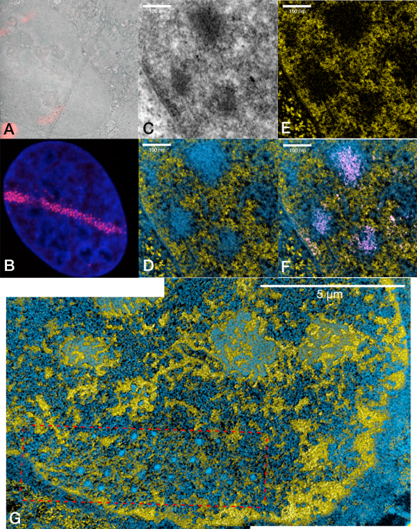 Figure 5.
U2OS cell line stably expressing Rad52-miniSOG-mCherry and damaged by laser-micro-irradiation.
Please click here to view a larger version of this figure.
(A) Overlay of a fluorescence image with a low-magnification TEM image showing a laser microirradiated U2OS nucleus with a damage track at the lower left.
(B) Representative confocal fluorescence microscopy image of a laser micro irradiated Hoechst-stained nucleus (blue) expressing Rad52-miniSOG-mCherry showing the characteristic pattern of small foci along the damage track (red signal).
(C) Conventional TEM, (D) ESI, (E) phosphorus map, (F) ESI and segmented signal from (C) High magnification of the nucleus shown in the upper left.
(G) ESI image of another U2OS nucleus stably expressing Rad52-miniSOG-mCherry showing a laser-induced damage track in the context of the whole nucleus.
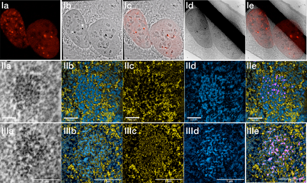 Figure 6.
U2OS cells stably expressing 53BP1-miniSOG-mCherry irradiated with 2 Gy and fixed after 30 min.
Please click here to view a larger version of this figure.
(I) a) Fluorescence image showing the gamma irradiation-induced 53BP1 foci. b) Transmitted light image after photopolymerization. c) Overlay of the fluorescence with the transmitted light image. d) Low magnification TEM image (the black stripe is a TEM grid bar). e) Overlay of the fluorescent image with the low magnification TEM image.
(II) Damage focus labelled with an asterisk in the transmitted light image recorded in normal TEM and in ESI mode. a) Zero-loss, b) ESI, c) Phosphorus, d) Protein e) Overlay ESI and segmented signal from the zero-loss image.
(III) Damage focus labeled with a cross in the fluorescence image recorded in normal TEM and in ESI mode. a) Zero-loss, b) ESI, c) Phosphorus, d) Protein e) Overlay ESI and segmented signal from the zero-loss image.
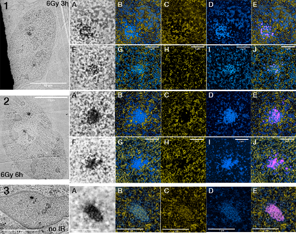 Figure 7.
Changes in foci structure between foci after different times of irradiation.
Please click here to view a larger version of this figure.
U2OS 53BP1 miniSOG mCherry cells exposed to 6 Gy of gamma irradiation fixed after 3h (1A-E,F-J) and 6h (2A-E,F-J) respectively. 3 shows an unirradiated U2OS 53BP1 miniSOG mCherry nucleus showing a cryptic focus (A-E). ESI pictures are presented in the order ESI (nucleic acid and protein), nucleic acid (alone), protein (alone), ESI (nucleic acid and protein) + segmented miniSOG signal.
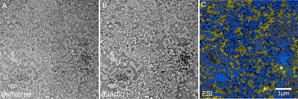 Figure 8.
DNA-repair foci are still visible in conventional transmission mode when post fixation with osmium tetroxide is omitted.
Please click here to view a larger version of this figure.
Ultrathin section (50 nm) of an U2OS nucleus showing two 53BP1 foci from a sample that was not treated with osmium tetroxide. (A) In conventional TEM mode, it is possible to see sites stained by the DAB polymer even without enhancing contrast with the heavy metal stain. (B) The contrast of the foci can be further enhanced by taking zero-loss images (filtering away all electrons that origin from plural scattering events).
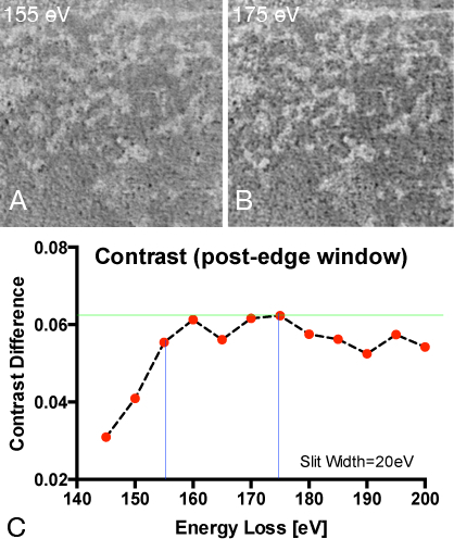 Figure 9.
Determination of the optimal energy window settings for mapping phosphorus
(A) Elemental ratio map recorded for phosphorus with post edge at 155 eV and pre-edge at 120 eV.
(B) Elemental ratio map recorded for phosphorus with post edge at 175 eV and pre-edge at 120 eV.
(C) Calculating phosphorus ratio maps from a constant pre-edge window at 120 eV energy loss and a variable post-edge window ranging from 140-200eV energy loss in order to determine the combination that is best in contrast. The intensity difference of the brightest and the dimmestpixel in a line-scan spanning over the same phosphorus rich and phosphorus poor region shows highest contrast values (dynamic range) when a post-edge picture of 175 eV energy loss was chosen.
Discussion
ESI can serve as an excellent tool for examining different states of chromatin and ribonucleoproteins in the nucleus because it is able to specifically map areas that are rich in phosphorus. It profoundly augments the amount of detail that can be obtained by an electron microscope and is not dependent on nonspecific contrasting methods. One disadvantage of ESI is that it requires thinner sections than conventional TEM at the same accelerating voltage. This can be overcome by working with serial sections or using tomographic methods28.
Although a lot of information can be obtained by looking at the distributions of phosphorus and nitrogen, it is of interest to be able to also map the distribution of certain proteins. With the method presented in this paper, it was demonstrated that ESI could be combined with methods that are based on the site-specific polymerization of diaminobenzidine. Although this method does not add a full new color to ESI, it is clearly useful to map the distribution of a protein. This applies in particular to proteins that interact with the chromatin. If a study needs to visualize more than one protein population, the labeling methods using immunogold can still be used when applied as pre-embedding staining, prior to photo-oxidation9. Compared to stable cell lines, transient transfections have the disadvantage that expression levels can vary significantly between cells and thus make it hard to find multiple cells expressing similar amounts of the tagged protein. Therefore, the creation of stable cell lines is recommended. However, it is possible to judge the relative amount of protein expression using fluorescence imaging and select cells with intermediate expression following transient transfection.
Although the miniSOG fusion tag is fluorescent itself, its quantum yield is significantly worse than GFP (0.37 vs. 0.6)10. For the purpose of correlative microscopy, adding an additional fluorescent protein tag like mCherry allows imaging in the live cells without the production of singlet oxygen that occurs with miniSOG excitation. The expression level of the miniSOG-tagged proteins, the amount of oxygen in the DAB-containing buffer, and the pH can also affect the speed of photo-oxidation. Sometimes it can be quite problematic to achieve homogenous photo-oxidation in the region of interest because of the light dependence of the photo-oxidation reaction. Prolonged photo-oxidation can lead to nonspecific staining and the deposition of too much heavy metal in the sample, which can complicate the detection of element-specific signals by ESI. The photo-oxidation process is quite time consuming so that usually only a very small region containing a few cells on the coverslip are normally stained.
We have shown the combination of miniSOG tagged proteins with ESI using a monolayer of an adherent human cancer cell line. In principal, the method can also be applied to any other sample (yeast, bacteria, tissue, embryo) as long as it is possible to express the miniSOG-tagged protein at reasonable levels and as long translucency and the diffusion of oxygen and DAB is sufficiently high to allow proper photo-oxidation and thus homogenous staining. For suspension cells, it would be advantageous to fix the location of cells on a cover slip using an adhesive such as poly-L-lysine. For thicker samples, objectives with a lower numerical aperture will achieve a more homogenous illumination but take longer to photo-oxidize.
We have presented the use of the miniSOG-tagged fusion proteins as close to the original protocol published by Shu et al. 10 as possible – including the use of osmium tetroxide. There it could be observed that, apart from preferentially depositing on DAB-polymers and membranes, osmium tetroxide shows some reactivity and deposition on most of the biological material in the specimen (10 Figure 3). Osmium tetroxide has an elemental edge at 45 eV. This signal and its plasmons can be superimposed on the electron energy loss spectrum as the thickness of the specimen increases and single electrons undergo multiple energy loss events during passage through the specimen. This can limit the quality of the phosphorus elemental maps if high OsO4 concentrations are used in sample preparation. The concentrations that we have used here, which are significantly lower than what was used previously 10, allowed the generation of good quality phosphorus maps. In an experiment using miniSOG tagged proteins that demands higher OsO4 concentrations, the best concentration that still allows good phosphorus map creation will have to be determined empirically.
We have found that the DAB polymer that forms at the DNA repair foci is sufficiently dense to be seen in conventional TEM mode (or in zero-loss mode with even better contrast) even when post-fixation with osmium tetroxide is omitted (see Figure 8). The segmentation of the signals that were recorded this way was as robust as using the samples that were treated with osmium. Depending on the nuclear protein that has to be visualized, the size of the structures it forms and the necessity to visualize membrane systems, the use of osmium tetroxide might not be necessary and its omission will remove the potential of masking the elemental signature of phosphorus.
Compared to other publications using ESI 18,29,30 we have used different settings for the pre- and post-edge pictures in order to generate elemental ratio maps with the least amount of noise. We have empirically determined the settings presented in the manuscript (see figure 9). The chosen settings around the edges should lead to correct elemental maps unless the collection windows are overlapping with other elements that are present in the sample. In our case, sulphur could be such an element. Since the concentration of sulphur (which occurs in the amino acids methionine and cysteine) is very low and contributes to the calculated map only in a negligible amount, we believe the better S/N ratio that we obtained using the settings used here outweighs the disadvantages that might arise from traces of sulphur in the sample.
We revealed the ultrastructure of DRFs at nanometer resolutions using the DNA repair proteins MDC1, 53BP1 and Rad52 combined with ESI and TEM techniques. The organization of the chromatin and individual DSB repair protein localization was resolved using this approach. Their localization in domains rich in DNA lesions following laser micro-irradiation DNA and the tendency of repair proteins to fill the space between the chromatin ridges was shown. In the case of Rad52, which plays a role in homologous recombination, the formation of nuclear body-like spherical structures along the laser-damaged track could be observed and this was in contrast to the other two tested proteins. When the damage is applied by gamma irradiation, 53BP1 formed foci around the damaged chromatin. The relative composition and position of chromatin and protein in the foci seems to change over time. The relationship between these proteins and the damaged chromatin as well as changes in the organization of chromatin and the composition of nuclear bodies can all easily be obtained using the ESI technique whereas conventional brightfield microscopy using uranium and lead as contrasting agents cannot assess these properties directly. Thus, this technique shows high potential for the study of structure-function relationships, particularly for processes acting on DNA.
Disclosures
The authors have nothing to disclose.
Acknowledgments
We thank Dr. Roger Tsien for providing us with the miniSOG constructs. Dr. Xuejun Sun for help with the TEM. Lisa Lem, and Peter Shipple from the Cross Cancer Institute for supplying oxygen. Hilmar Strickfaden holds a postdoctoral fellowship by the Alberta Cancer foundation and was supported by the Bayrische Forschungsallianz. This work was supported by grants from the Canadian Institutes of Health Research and Alberta Cancer Foundation.
References
- Schermelleh L, Heintzmann R, Leonhardt H. A guide to super-resolution fluorescence microscopy. The Journal of Cell Biology. 2010;190:165–175. doi: 10.1083/jcb.201002018. [DOI] [PMC free article] [PubMed] [Google Scholar]
- Bazett-Jones DP, Hendzel MJ, Kruhlak MJ. Stoichiometric analysis of protein- and nucleic acid-based structures in the cell nucleus. Micron (Oxford, England: 1993) 1999;30:151–157. doi: 10.1016/s0968-4328(99)00019-0. [DOI] [PubMed] [Google Scholar]
- Michael J Hendzel FMB, Bazett-Jones DP. Direct Visualization of a Protein Nuclear Architecture. Molecular biology of the cell. 1999;10:2051. doi: 10.1091/mbc.10.6.2051. [DOI] [PMC free article] [PubMed] [Google Scholar]
- Ottensmeyer FP, Andrew JW. High-resolution microanalysis of biological specimens by electron energy loss spectroscopy and by electron spectroscopic imaging. Journal of ultrastructure research. 1980;72:336–348. doi: 10.1016/s0022-5320(80)90069-6. [DOI] [PubMed] [Google Scholar]
- Leapman RD, Ornberg RL. Quantitative electron energy loss spectroscopy in biology. Ultramicroscopy. 1988;24:251–268. doi: 10.1016/0304-3991(88)90314-2. [DOI] [PubMed] [Google Scholar]
- Simon GT. Electron spectroscopic imaging. Ultrastructural pathology. 1987;11:705–710. doi: 10.3109/01913128709048457. [DOI] [PubMed] [Google Scholar]
- Egerton R. Electron Energy-Loss Spectroscopy in the Electron Microscope. Springer; 2011. [Google Scholar]
- Aronova MA, Kim YC, Zhang G, Leapman RD. Quantification and thickness correction of EFTEM phosphorus maps. Ultramicroscopy. 2007;107:232–244. doi: 10.1016/j.ultramic.2006.07.009. [DOI] [PMC free article] [PubMed] [Google Scholar]
- Hopkins C, Gibson A, Stinchcombe J, Futter C. Chimeric molecules employing horseradish peroxidase as reporter enzyme for protein localization in the electron microscope. Methods in enzymology. 2000;327:35–45. doi: 10.1016/s0076-6879(00)27265-0. [DOI] [PubMed] [Google Scholar]
- Shu X, et al. A Genetically Encoded Tag for Correlated Light and Electron Microscopy of Intact Cells, Tissues, and Organisms. PLoS biology. 2011;9:e1001041. doi: 10.1371/journal.pbio.1001041. [DOI] [PMC free article] [PubMed] [Google Scholar]
- Gaietta G, et al. Multicolor and electron microscopic imaging of connexin trafficking. Science (New York, NY) 2002;296:503–507. doi: 10.1126/science.1068793. [DOI] [PubMed] [Google Scholar]
- Fernandez-Capetillo O, Celeste A, Nussenzweig A. Focusing on foci: H2AX and the recruitment of DNA-damage response factors. Cell cycle (Georgetown, Tex) 2003;2:426–427. [PubMed] [Google Scholar]
- Haaf T, Golub EI, Reddy G, Radding CM, Ward DC. Nuclear foci of mammalian Rad51 recombination protein in somatic cells after DNA damage and its localization in synaptonemal complexes. Proceedings of the National Academy of Sciences of the United States of America. 1995;92:2298–2302. doi: 10.1073/pnas.92.6.2298. [DOI] [PMC free article] [PubMed] [Google Scholar]
- Maser RS, Monsen KJ, Nelms BE, Petrini JH. hMre11 and hRad50 nuclear foci are induced during the normal cellular response to DNA double-strand breaks. Molecular and Cellular Biology. 1997;17:6087–6096. doi: 10.1128/mcb.17.10.6087. [DOI] [PMC free article] [PubMed] [Google Scholar]
- Bekker-Jensen S, Mailand N. Assembly and function of DNA double-strand break repair foci in mammalian cells. DNA repair. 2010;9:1219–1228. doi: 10.1016/j.dnarep.2010.09.010. [DOI] [PubMed] [Google Scholar]
- Chapman JR, Sossick AJ, Boulton SJ, Jackson SP. BRCA1-associated exclusion of 53BP1 from DNA damage sites underlies temporal control of DNA repair. Journal of cell science. 2012;125:3529–3534. doi: 10.1242/jcs.105353. [DOI] [PMC free article] [PubMed] [Google Scholar]
- Dellaire G, Kepkay R, Bazett-Jones DP. High resolution imaging of changes in the structure and spatial organization of chromatin, gamma-H2A.X and the MRN complex within etoposide-induced DNA repair foci. Cell cycle (Georgetown, Tex) 2009;8:3750–3769. doi: 10.4161/cc.8.22.10065. [DOI] [PubMed] [Google Scholar]
- Kruhlak MJ, et al. Changes in chromatin structure and mobility in living cells at sites of DNA double-strand breaks. The Journal of Cell Biology. 2006;172:823–834. doi: 10.1083/jcb.200510015. [DOI] [PMC free article] [PubMed] [Google Scholar]
- Goodson HV, Dzurisin JS, Wadsworth P. Generation of stable cell lines expressing GFP-tubulin and photoactivatable-GFP-tubulin and characterization of clones. Cold Spring Harbor protocols. 2010;2010 doi: 10.1101/pdb.prot5480. [DOI] [PubMed] [Google Scholar]
- Zeyda M, Borth N, Kunert R, Katinger H. Optimization of sorting conditions for the selection of stable, high-producing mammalian cell lines. Biotechnology progress. 1999;15:953–957. doi: 10.1021/bp990089g. [DOI] [PubMed] [Google Scholar]
- Dellaire G, Nisman R, Bazett-Jones DP. Correlative light and electron spectroscopic imaging of chromatin in situ. Methods in enzymology. 2004. pp. 375–456. [DOI] [PubMed]
- Campbell S, Ismail IH, Young LC, Poirier GG, Hendzel MJ. Polycomb repressive complex 2 contributes to DNA double-strand break repair. Cell cycle. 2013;12:2675–2683. doi: 10.4161/cc.25795. [DOI] [PMC free article] [PubMed] [Google Scholar]
- Mortusewicz O, et al. Recruitment of RNA polymerase II cofactor PC4 to DNA damage sites. J Cell Biol. 2008;183:769–776. doi: 10.1083/jcb.200808097. [DOI] [PMC free article] [PubMed] [Google Scholar]
- Bekker-Jensen S, et al. Spatial organization of the mammalian genome surveillance machinery in response to DNA strand breaks. The Journal of Cell Biology. 2006;173:195–206. doi: 10.1083/jcb.200510130. [DOI] [PMC free article] [PubMed] [Google Scholar]
- Ferrando-May E, et al. Highlighting the DNA damage response with ultrashort laser pulses in the near infrared and kinetic modeling. Frontiers in genetics. 2013;4:135. doi: 10.3389/fgene.2013.00135. [DOI] [PMC free article] [PubMed] [Google Scholar]
- Lukas C, et al. 53BP1 nuclear bodies form around DNA lesions generated by mitotic transmission of chromosomes under replication stress. Nature. 2011;13:243–253. doi: 10.1038/ncb2201. [DOI] [PubMed] [Google Scholar]
- Harrigan JA, et al. Replication stress induces 53BP1-containing OPT domains in G1 cells. The Journal of Cell Biology. 2011;193:97–108. doi: 10.1083/jcb.201011083. [DOI] [PMC free article] [PubMed] [Google Scholar]
- Aronova MA, et al. Reprint of 'Three-dimensional elemental mapping of phosphorus by quantitative electron spectroscopic tomography (QuEST) J. Struct. Biol. 2007;161:322–335. doi: 10.1016/S1047-8477(08)00062-2. [DOI] [PubMed] [Google Scholar]
- Fussner E, et al. Constitutive heterochromatin reorganization during somatic cell reprogramming. The EMBO journal. 2011;30:1778–1789. doi: 10.1038/emboj.2011.96. [DOI] [PMC free article] [PubMed] [Google Scholar]
- Kepkay R, Attwood KM, Ziv Y, Shiloh Y, Dellaire G. Cell cycle. Vol. 10. Georgetown, Tex: 2011. KAP1 depletion increases PML nuclear body number in concert with ultrastructural changes in chromatin; pp. 308–322. [DOI] [PubMed] [Google Scholar]


