Abstract
X-ray absorption studies of dilute samples require fluorescence detection techniques. Since signal-to-noise ratios are governed by the ratio of fluorescent to scattered photons counted by a detector, solid state detectors which can discriminate between fluorescence and scattered photons have become the instruments of choice for trace element measurements. Commercially available 13 element Ge array detectors permitting total count rates < 500000 counts per second are now in routine use. Since X-ray absorption beamlines at high brightness synchrotron sources can already illuminate most dilute samples with enough flux to saturate the current generation of solid state detectors, the development of next-generation instruments with significantly higher total count rates is essential. We present the design and current status of the 100 element Si array detector being developed in a collaboration between the NSLS and the Instrumentation Division at Brookhaven National Laboratory. The detecting array consists of a 10×10 matrix of 4 mm×4 mm elements laid out on a single piece of ultrahigh purity silicon mounted at the front end of a liquid nitrogen dewar assembly. A matrix of charge sensitive integrating preamplifiers feed signals to an array of shaping amplifiers, single channel analyzers, and scalers. An electronic switch, delay amplifier, linear gate, digital scope, peak sensing A/D converter, and histogramining memory module provide for complete diagnostics and channel calibration. The entire instrument is controlled by a LabView 2 application on a MacII ci; the software also provides full control over beamline hardware and performs the data collection.
1. Introduction
X-ray absorption spectroscopy is an important tool in the physical and biological sciences [1]. Modern X-ray and UV light sources provide high photon fluxes over a continuous energy spectrum, allowing monochromatization and hence selection of the atomic species for study. In many experiments, however, small concentrations and quantities of sample result in low signal levels which must be monitored with X-ray fluorescence techniques and distinguished from a large background of scattered radiation.
General requirements for detector sensitivity and the need to discriminate against a background of elastically scattered photons has led to the development and commercialization of solid state detectors based on intrinsic semiconductor diodes as detecting elements. The current generation of such detectors feature 13 channels and have greatly facilitated X-ray absorption spectroscopy studies of dilute systems [2]. These detectors are easily saturated, however, and further detector developments are needed to make full use of the available signal photons either by increasing single element count rates [3] or increasing the number of channels [4]. Major efforts are already under way to address the need for larger arrays of solid state detectors, including a design based on HgI2 detector elements [4]. In this paper we discuss the design, current status, and applications of the NSLS 100 element solid state detector, a next generation instrument being developed in a collaboration between the National Synchrotron Light Source and the Instrumentation Division at Brookhaven National Laboratory.
2. Motivation
For dilute species, the indirect measurement of X-ray absorption via detection of the fluorescence arising from the radiative decay of the core-hole produced in an absorption event is more sensitive than the direct transmission measurement. In real experiments, the radiation detected as emanating from a sample illuminated with a monochromatic X-ray beam typically comprises a weak fluorescence signal from the desired element and a much larger component of elastically scattered photons. This is aggravated if a sample contains a lattice material or crystalline domains which can produce Bragg reflections in the solid angle subtended by the fluorescence detector. The sample matrix may also contain other elements within a few atomic numbers of the desired species which contribute their own fluorescence background.
Since the noise in a photon-statistics-limited experiment scales with the square root of the total number of counts registered by a detector, instruments which can distinguish between signal fluorescent photons and background scattered photons are inherently capable of yielding data with better signal-to-noise ratios. For a sample with a fluorescence intensity of If and a scattered background intensity of Ib, a detector which responds to both signals will have a signal-to-noise ratio which scales as
whereas an energy discriminating detector which responds only to the fluorescence photons will have a S/N ratio proportional to
where t is the integration time over which data is collected. It is important to note that the ratio of Ib to If is essentially a fixed characteristic of a sample. The statistics of the measurement can only be improved by increasing the integration time or the incident flux exciting the sample [5].
A limitation of an energy discriminating instrument is that the signals corresponding to different photons striking the same detector element must be processed (shaped) in a manner which minimizes pileup effects while maximizing the signal-to-noise ratio. One is forced to make tradeoffs since high rates suggest short pulse peaking times while improved S/N ratios require somewhat longer shaping. The result is that existing solid state detectors have maximum count rates on the order of 30000 photons per second per element before saturation effects start to become evident (higher count rates can be used if a systematic empirical dead-time correction is made) [6]. The number of elements into which a given solid angle is divided thus determines the total count rate which can be tolerated, and hence the degree to which the counting statistics can be improved with higher incident flux.
In an example case where a sample has a ratio of scattered (Ib) to fluorescent intensity (If) of 100:1, a 13 element detector can count a maximum of approximately 3900 fluorescent photons per second. To acquire the customary 106 counts of signal thus requires a minimum of 4.3 min per point, or 18 h for a 250 point EXAFS scan! The objective of the NSLS 100 element detector project is to increase the maximum count rate by an order of magnitude, permitting experiments such as the one above to be completed in a few hours and allowing systems with even lower If/Ib ratios to be studied within reasonable time periods. The miniaturization and cost-reduction required to realize a 100 channel instrument should also significantly benefit future construction of solid state detectors with more or fewer elements as necessary.
3. Design overview
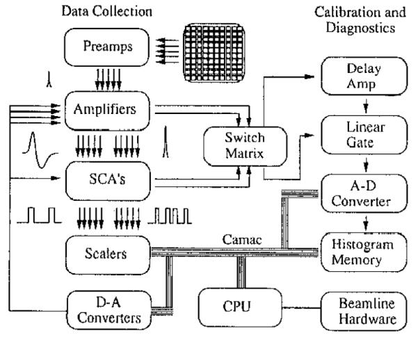
A block diagram of the detector system is shown in fig. 1. The data collection path is straightforward, with 100 detecting elements feeding charge proportional to the energy of the detected photon into 100 preamplifiers which provide initial charge to voltage conversion. This is followed by 100 fast/slow shaping amplifiers which provide further gain and condition the slow signals for energy discrimination via pulse height analysis with 100 single channel analyzers. Each SCA generates a logic pulse when a signal has met the upper and lower threshold conditions, i.e. corresponds to a photon in the selected energy range. These pulses are counted in scalers which are enabled during the data collection integration time. Each shaping amplifier also produces a so-called “fast” signal which is compared against an independent lower threshold in each SCA to yield a total count rate, that is, one logic true pulse for each photon regardless of its energy. This latter signal is also counted in scalers to allow for possible dead-time corrections or other statistical manipulations.
Fig. 1.

Block diagram of 100 element solid state array detector.
The diagnostics and calibration path begins at a programmable switch which selects which channel is to be examined. A delay amplifier produces a delayed version of the signal pulse which is then presented to a linear gate which passes the signal through only if a logic true pulse has been delivered from the associated single channel analyzer. The signal pulse is then digitized with a peak sensing A/D converter and counted in a histogramming memory module. The gate may alternatively be bypassed such that every signal pulse is passed to the A/D converter. In this fashion it is possible to view, in close to real time, the energy spectrum of the photons being emitted from the sample and ensure that the SCA thresholds have been adjusted to accurately accept the desired fluorescence photons.
4. Hardware
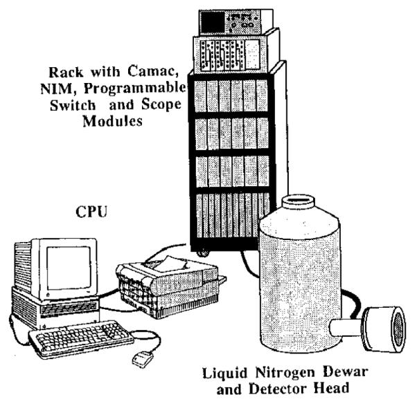
The detector comprises three physically separate components as shown in fig. 2: a liquid nitrogen dewar assembly with an evacuated head which contains the actual detecting elements and the preamplifiers; a rack of electronics with a CAMAC crate, three NIM bins, a programmable switch, and a digitizing scope; and a controlling computer. The instrument has been designed to provide a 300 eV resolution at 6 keV, and provide an overall energy coverage of roughly 2–20 keV.
Fig. 2.

Components of the 100 element detector.
The photon detecting element is a single piece of 300 μm thick silicon which has been masked and metallized in several steps to provide an array of one hundred 4 mm × 4 mm anodes in a 5 cm × 5 cm area. A common cathode made of thin aluminum is deposited on the opposite surface. During operation a 50 V bias is applied which sweeps electrons promoted into the conduction band by the absorption of an X-ray photon to the anodes. Table 1 lists representative signal magnitudes for selected X-ray energies, and it is of interest to note that the design resolution of 300 eV corresponds to a noise level of ±50 electrons. The energy range the detector can cover is limited at the low end (~ 2 keV) by the decreasing transmittance of the entrance window, and the high end (~ 18 keV) by the Si becoming transparent to the fluorescence photons.
Table 1.
Performance parameters for Si detector for photons of different energies
| Photon energy [keV] |
Electrons collected |
Charge collected [C] |
Preamp output (Cf = 0.33 pF) |
Shaping amp output [V] |
|---|---|---|---|---|
| 2.2 | 608 | 9.7×10⁻¹⁷ | 0.30 | 0.73 |
| 4.5 | 1243 | 2.0×10⁻¹⁶ | 0.60 | 1.50 |
| 10.0 | 2762 | 4.4×10⁻¹⁶ | 1.34 | 3.33 |
| 17.0 | 4696 | 7.5×10⁻¹⁶ | 2.28 | 5.67 |
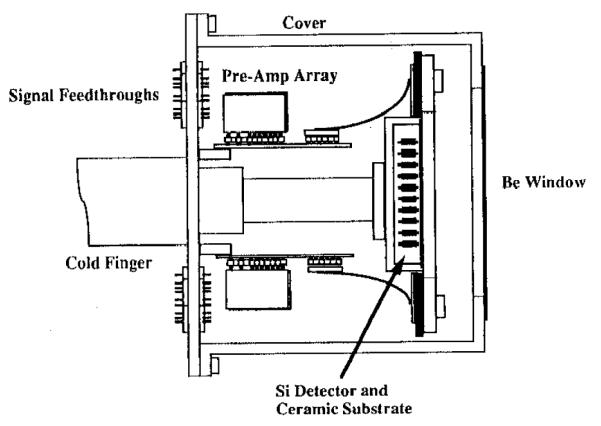
Immediately behind the detector is mounted a hand-assembled, ceramic substrate which holds the first “front end” components of an array of 100 low noise preamplifiers: charge collecting capacitors, precision feedback resistors and FET transistors. The silicon/ceramic assembly is mounted within the evacuated detector head of a Canberra solid state detector dewar, shown in fig. 3, behind a thin beryllium window which is transparent to hard X-rays. Thermal contact with a cold finger at liquid nitrogen temperature suppresses thermal noise. The “back ends” of the preamplifiers are held in two arrays of 17 hybrid circuits, each with three channels, mounted on two motherboards, also within the evacuated front end. External connections are accomplished with electrical feedthroughs.
Fig. 3.

Detector head cross-section drawing.
Signals are bussed from the detector dewar assembly to the electronics rack with approximately 30 ft of ribbon coaxial cable. The shaping amplifiers, also hybrid circuits developed at BNL, are arranged as sixteen channels within a double wide NIM bin module. Each amplifier has a fine gain adjustment which can be programmed with a dc voltage level to modify the nominal voltage gain of 2500 by ±25%, as well as an electronic enable/disable control which is used to address a single channel for diagnostics. The amplifiers have both a fast (150 ns shaping time) unipolar output and a slower (~ 2 μs) bipolar output, the latter of which yields a count rate ~ 10000 pulses/s before 10% pileup. From the amplifier modules, the signals are routed via ribbon cable into matching arrays of single channel analyzers and fast threshold discriminators, also comprising 16 hybrid circuits in a double wide NIM module. The SCAs are also programmable via dc voltages: a lower and upper threshold for energy discrimination, and a lower threshold for total count rate determination. Each SCA output is counted in a separate channel in LeCroy 4434 scaler modules in the CAMAC crate for time intervals controlled by a DSP RTC 018 real time clock.
The detector computer, an Apple MACINTOSH II Ci, controls the amplifier and SCA parameters via a bank of CAMAC based DSP 3016 D/A converters. It also interacts with the LeCroy 3512 A/D converter, LeCroy 3588 histogramming memory, Tektronix TSI 8150 programmable switch crate equipped with TSS44 coax scanners, and Tektronix 2221 digital storage scope which make up the diagnostic side of the instrument. All interfacing is via an IEEE-488 bus.
5. Software
The detector software is a user friendly Labview 2 [7,8] application which is divided into two sections: calibration and diagnostics, and data collection. The calibration software implements a multichannel analyzer by rapidly reading out the contents of the histogramming memory and plotting the counts versus energy (voltage) on the computer monitor. After the user selects and adjusts a template channel with a standard X-ray source of known energy, the software automatically adjusts the gains in the remaining 99 channels to match with a small feedback routine. The SCA windows may then be simply adjusted by the user to select the fluorescent energy desired.
The monitoring of fluorescence from multiple atomic species is possible either simultaneously by dedicating a fraction of the channels to use different SCA windows or sequentially by having all channels have the same windows at any one time, but alternating between two or more SCA windows temporally. Either scheme in principle permits the advantageous measurement of the incident flux, which is needed for normalization of the collected spectra, with the same detection method as used for the fluorescence measurement. Facilities are provided for monitoring the windowed and total count rates as a function of pixel number for optimizing the data collection geometry and detecting Bragg reflections which may occur.
The data collection routines provide the standard ability to define and execute X-ray fluorescence measurement scans with varying energy steps and integration times. Collected data is plotted in real time, allowing continual evaluation of the progress of the experiment. A serial connection between the detector and the beamline computers is used to coordinate the adjustment of the beamline optics and the instrument operation. A convention has been defined in which the detector computer requests a particular X-ray energy and waits until the beamline computer has adjusted the monochromator and any other relevant parameters and responds that data collection may begin. This will permit the detector to be used with any synchrotron beamline which supports the simple interfacing convention.
The software has been designed to accommodate a flexible range of detector hardware configurations, including instruments with larger or fewer numbers of channels. All device-dependent code has been embedded in an identified set of low level routines which should make the implementation of new detectors a rapid process.
6. Current status
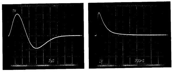
The detector development project has progressed rapidly, and a prototype testing arrangement with three channels completely implementing the design described above will be tested with X-rays in early 1992. The preamplifiers, shaping amplifiers, and SCAs have been hybridized; and sample scope traces from the fast and slow channels of the amplifier hybrid are shown in fig. 4. Artwork has been generated for the Si detector wafer and associated ceramic overlay; though these will not be produced until the three channel prototype system has been fully demonstrated and the mass replication of the hybrids has been initiated. The cryogenic dewar, detector head with beryllium window, and the preamplifier array motherboards are complete. The motherboards for the NIM based shaping amplifier and SCA arrays have yet to be designed.
Fig. 4.
Sample scope traces of output from prototype shaping amplifier hybrid circuit with slow and fast channels.
All other componentry has been procured and installed in the electronics rack. The software has been fully completed, including all calibration, diagnostics, and data-collection functions described.
7. Applications
Solid state detectors are already essential tools for X-ray spectroscopy in fields ranging from structural biology to surface science. In biological EXAFS, for example, counting rates are typically low due to millimolar or submillimolar maximum concentrations of enzymes and proteins, and 8–24 h of data collection are typically required for complete EXAFS spectra of a single sample. Such long exposures often result in significant X-ray damage which, at the minimum, complicates the interpretation of collected data. XANES measurements on dilute systems require typically a minimum of approximately 3 min, preventing dynamical studies of all but the slowest of systems.
The development of next generation solid state detectors such as the HgI2 detector [4] and the instrument described here, will facilitate these and other kinds of measurements by permitting EXAFS and XANES measurements to be made on more dilute systems, with considerably shorter integration times, and with less difficulty for highly scattering samples. Representative examples of other experiments which will benefit include studies of surfaces with monolayer and submonolayer coverages, crystalline or polycrystalline solids, and frozen solutions. Shorter integration times in principal allow studies of dynamic systems, though timescales will still be slow by most kinetic standards. The gain in sensitivity provided by the small dead area is of benefit for the scanning of heterogeneous materials with small (< 100 μm), focused beam spots.
Development of the miniature electronics for the next generation detectors will result in a significant reduction in the cost per channel for amplifiers and single channel analyzers. It should therefore be possible in the near future to design experimental arrangements with even more elements or, for example, sample chambers in which detector elements are included as integral parts. Ultimately, however, even the present level of miniaturization and integration is insufficient to handle the count rates anticipated with the next generation of synchrotron light sources, and progress is needed towards single chip X-ray detectors.
8. Conclusion
The full sensitivity of fluorescence X-ray absorption spectroscopy is only achieved when:
-
1)
the detector has sufficient resolution to separate the desired trace element fluorescence from background signals,
-
2)
the detector is fast enough to respond to all available photons, and
-
3)
the detector subtends a large solid angle with small dead area.
The NSLS 100 element solid state detector is designed to meet these criteria and help advance the state of the art in X-ray detector technology. It will significantly enhance the range of feasible experiments for X-ray absorption studies in a variety of fields.
References
- [1].Stern EA, Heald SM. In: Handbook of Synchrotron Radiation. Koch EE, editor. Vol. 1. North-Holland, Amsterdam: 1983. See e.g. and references therein. [Google Scholar]
- [2].Cramer SP, Tench O, Yocum M, George GN. Nucl. Instr. and Meth. 1988;A266:586. [Google Scholar]
- [3].Derbyshire GE, Dent AJ, Dobson BR, Farrow RC, Felton A, Greaves GN, Morrell C, Wells MP. Rev. Sci. Instr. 1992;63:814. [Google Scholar]
- [4].Iwanczyk JS, Dorri N, Wang M, Szawlowski M, Warburton WK, Hedman B, Hodgson KO. Rev. Sci. Instr. 1989;60:1561. [Google Scholar]
- [5].Filters can improve If/Ib, but are typically limited in performance by nonideal behavior.
- [6].Zhang K, Rosenbaum G, Bunker G. to be published.
- [7].National Instruments. Austin, TX, USA: [Google Scholar]
- [8].Kirkman IW, Buksh PA. Rev. Sci. Instr. 1992;63:869. [Google Scholar]


