Abstract
Shielded 137Cs irradiators are routinely used in pre-clinical radiation research to perform in vitro or in vivo investigations. Without appropriate dosimetry and irradiation protocols in place, there can be large uncertainty in the delivered dose of radiation between irradiated subjects that could lead to inaccurate and possibly misleading results. Here, a dosimetric evaluation of the JL Shepard Mark I-68A 137Cs irradiator and an irradiation technique for whole-body irradiation of small animals that allows one to limit the between subject variation in delivered dose to ±3% are provided. Mathematical simulation techniques and Gafchromic EBT film were used to describe the region within the irradiation cavity with homogeneous dose distribution (100% ±5%), the dosimetric impact of varying source-to-subject distance, and the variation in attenuation thickness due to turntable rotation. Furthermore, an irradiation protocol and dosimetry formalism that allows calculation of irradiation time for whole-body irradiation of small animals is proposed, that is designed to ensure a more consistent dose delivery between irradiated subjects. To compare this protocol with the conventional irradiation protocol suggested by the vendor, high-resolution film dosimetry measurements evaluating the dose difference between irradiation subjects and the dose distribution throughout subjects was performed, using phantoms resembling small animals. Based on these results, there can be considerable variation in the delivered dose of > ±5% using the conventional irradiation protocol for whole-body irradiation doses below 5 Gy. Using the proposed irradiation protocol this variability can be reduced to within ±3% and the dosimetry formalism allows for more accurate calculation of the irradiation time in relation to the intended prescription dose.
Keywords: Radiation dosimetry, Cesium-137, Whole-body irradiation, Pre-clinical research
Introduction
X- and γ-ray irradiators are widely used in radiobiological experiments to irradiate biological samples or animal subjects to observe their biological response to radiation.(Cummins and Delaney 1961, Zoetelief et al. 2001, Minniti and Seltzer 2007, Yoshizumi et al. 2011) In response to the increased concern regarding radiological emergencies, a network of Centers for Medical Countermeasures against Radiation (CMCR) was established in the United States in 2005, focusing on evaluating animal model responses to whole-body or partial-body radiation exposure. It is becoming clear that experiments involving animal models require accurate and reproducible irradiation dosimetry as a crucial part in radiobiological investigations.(Kazi et al. 2014) Without accurate and reproducible delivery of radiation dose, the results of radiobiological experiments will be hard to interpret and possibly misleading.
In terms of expected dose accuracy, uncertainty and uniformity, the International Commission on Radiation Units and Measurements (ICRU 1979) recommended a homogeneous ratio of < 1.10 and preferably < 1.05 between the maximum and minimum absorbed doses across the target volume and a combined standard uncertainty of 3.5% for radiobiological studies related to applications in radiation therapy. Although image-guided small animal irradiation systems are now commercially available(Bazalova et al. 2014), the vast majority of animal studies still utilize simpler, less sophisticated irradiation devices such as orthovoltage X-ray machines, Cesium-137 (137Cs) irradiators, or Cobalt-60 irradiators. Among them, 137Cs irradiators with rotating turntables are extensively used in many institutions.
Although manufacturers provide the output dose rate of 137Cs irradiators and isodose curves for each available irradiation position at the time of installation of the irradiator, investigators have reported that despite this there can be considerable uncertainty in the delivered radiation dose using 137Cs irradiators.(Rodriguez et al. 2003, Brady et al. 2009, Yoshizumi et al. 2011, Brady et al. 2012) There is also a variation in dose rate between different animals depending on their position inside the irradiator and the rotation of the turntable.(Brady et al. 2012)
To ensure accurate and homogenous radiation dose delivery for modern day pre-clinical radiological experiments there is a need to establish accurate irradiation protocols. Such protocols will play an important role in harmonizing radiobiological studies across different centers and investigators. Here, a dosimetry formalism and homogeneous irradiation protocol for whole-body irradiation of small animals are proposed for 137Cs irradiators, expected to limit the variability of the delivered radiation dose between animal subjects to within ± 3%.
Materials and Methods
The 137Cs irradiator
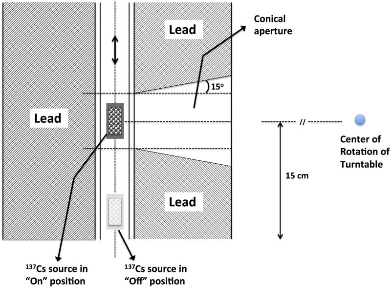
In this study a Mark I-68A 137Cs irradiator (JL Shepherd and Associates, San Fernando, CA) was used. The schematic and components of this irradiator are described in detail elsewhere (Brady et al. 2009). Hence, only a short description is given here. The irradiator has a self-shielded module (81 cm diameter × 198 cm tall), an interior irradiation cavity (31 cm wide × 36 cm tall × 31cm deep), a cylindrical source guide, a source indicator, and a turntable. The radiation source consists of two solid cesium chloride (CsCl) sources, encapsulated in stainless steel containers and welded to a translatable rod with an initial nominal activity A0 = 4000 Ci (per manufacturer's documentation) at the time of installation. Fig. 1 shows a schematic illustration of the irradiator setup. The geometric center of the source is approximately 15 cm above the irradiation cavity floor during times of “beam on”. Three positions, P1, P2 and P3, can be used to mount and rotate the turntable so that it is centered at distances which are 5, 15 and 20 cm from the source, respectively.
Figure 1.
Schematic illustration of the Mark I-68A 137Cs irradiator used in the current study.
Dose output verification
The dose rate given in the look-up tables for the 137Cs irradiator at the Albert Einstein College of Medicine was verified by obtaining the dose rate to water measured in air at static conditions (no table rotation) using an Exradin A12 farmer type ion chamber (Standard Imaging, Inc., Middleton, WI, USA), with a 137Cs energy point calibrated at the University of Wisconsin Accredited Dosimetry Calibration Laboratory (UWADCL). The in air measurement setting was achieved by suspending the ion chamber at the different isocenter points of the irradiator. At the time of measurement the dose rates measured at P1, P2, and P3 were found to be within 1.5% of the stated look-up table values of 11.235 Gy/min, 3.311 Gy/min, and 2.326 Gy/min, respectively. Since the expected uncertainty of these dose rate measurements is about 1.1% given all the related uncertainties for such a measurement added in quadrature, based on the uncertainty contribution factors from a recent publication summarizing the uncertainty of 137Cs dosimetry(Hassan et al. 2011), the stated look-up table values were used. 137Cs has a physical half-life of 30.2 years and as such the output is very stable and only needs to be corrected by the time decay factor (annual decay of 2.3%). For mortality and morbidity studies with steep dose-response curves it is important to investigate the potential variability in dose between irradiated subjects, as well as the dose rate output of the Cs-source.
Dose variation simulation for rotational irradiation
With respect to the dose to the irradiated animals, two factors have the largest influence on the accuracy of the delivered dose; namely the variation in source-to-subject distance (SSD) and the varied attenuation from animals shielding each other within the irradiation cavity. In order to evaluate the dosimetric influence of the turntable rotation (at constant rotation speed), mathematical calculations based on subject positions and Gafchromic EBT film dosimetry were employed to quantitatively analyze the resulting dose discrepancy and variability.
Mathematical simulation of SSD change due to turntable rotation
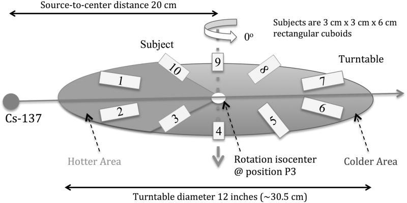
The variability in delivered dose among irradiated animals due to stopping at different angular positions at the end of irradiation can be minimized by decreasing the dose rate, i.e. increasing the source-axis distance (SAD) employing the largest SSDs by placing the turntable at position P3, as was done in this study. In order to study the effect on the expected delivered dose to subjects stopping at different positions within the irradiation chamber at the end of the irradiation experiment, 3 cm × 3 cm × 6 cm cuboid samples were simulated as placed on the irradiator turntable. Each sample center was assumed to be 6 cm away from the rotation isocenter. Ten subjects were uniformly distributed around the periphery of the turntable, and the turntable was placed at Position 3 at a distance of 20 cm from the source, as illustrated in Fig. 2. The change in dose from one rotation cycle due to the SSD change and changing attenuation thickness during rotation was simulated separately.
Figure 2.
Ten subjects are uniformly distributed around the periphery of the turntable, 6 cm away from the rotation axis. The subjects in the hotter area, the 108° sector closest to the Cs-source, experience a higher dose rate based on source-to-subject distance compared to the ones in the colder area.
Simulation of the change in attenuation thickness
Since the subjects have a certain volume and may be non-uniformly distributed on the turntable, the amount of tissue traversed by the irradiation beam before reaching a subject will vary with turntable rotation.
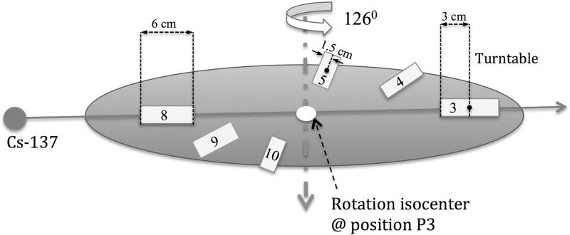
In Fig. 3, a typical partially loaded irradiation jig of small animals is illustrated. Six subjects (3 cm × 3 cm × 6 cm) are symmetrically loaded onto the turntable. The attenuation thickness to the midpoint, M, of the subjects includes the attenuation (shielding) by other animal subjects as well as the self-attenuation within one subject. With the animals diametrically opposed as in Fig. 3 the maximum attenuation thickness is 9 cm (3/2 × length of subjects), while the minimum attenuation thickness is 1.5 cm (1/2 × width of subjects), corresponding to a 40.5% or 6.8% dose reduction, respectively. This estimate is based on an attenuation rate of water at about 4.5% per cm for 137Cs γ-rays, given in Wheatley et al. (Wheatley et al. 1960). Moreover, to account for attenuation of dose at the rotation isocenter point due to the number of subjects loaded in the proposed dosimetry formalism detailed below, a simple correction based on the number of subjects and their length is proposed (Fig. 3). The load factor is denoted, LF, i.e. number of subjects loaded divided by maximum number of subjects that can be placed in the jig. Then, assuming that a sector in the jig is either completely filled or completely unfilled, a first order approximation of the mean attenuation thickness, AT, seen at the rotation isocenter during rotation is given by the product of the load factor and subject length, i.e. AT = LF × subject length. Thus, the mean attenuation factor, AF, at the rotation isocenter during rotation, is given by AF = AT × 0.045.
Figure 3.
Illustration showing the change in attenuation thickness with table rotation.
Dose measurement by film dosimetry
Gafchromic EBT film dosimetry setup
Because of the continuous turntable rotation, the geometric positions of the subjects are constantly changing, making it difficult to measure the absolute dose and dose distribution throughout the irradiated subjects. Thus, detectors with significant directional dependence like thermoluminescent dosimeter (TLD) chips, optically stimulated luminescence (OSL) dosimeters, or parallel ion chambers, are not appropriate. Cylindrical ion chambers, TLD rods or Gafchromic film can be used for such absolute and relative dose measurements, given appropriate calibration. In this study Gafchromic EBT film was chosen for the measurements, which agrees well with measurements taken by ion chambers and TLDs (Brady et al. 2009, Yoshizumi et al. 2011, Brady et al. 2012).
In this work a previously published film dosimetry protocol was followed for these measurements (Hardcastle et al. 2011). All films were digitized pre- and post-exposure using a 48-bit transmission/reflection flatbed photo scanner with its accompanying scanning software (Perfection V700 PHOTO, EPSON, Japan), placing the films at the same lateral position on the scanner bed using an opaque template to minimize the variations in lateral scatter from the light source (Hardcastle et al. 2011). This ensures a consistent light exposure of the films, however due to scattering of the light source in the field the response of the scanner is not flat over the field, and hence each scanned film is divided by a field flattening image to correct for this. The orientation of each film was marked to ensure correct placement of the film on the scanner between pre- and post-exposure scans, and Newton ring artifacts were addressed by making sure the film was placed so that it was not in direct contact with the scanner bed. (Hardcastle et al. 2011) The digitized EBT films were analyzed using open-source software (Image J). After comparing the H-D curves from the red, green and blue color channels, the red channel data was chosen for the dosimetric analysis in this study.
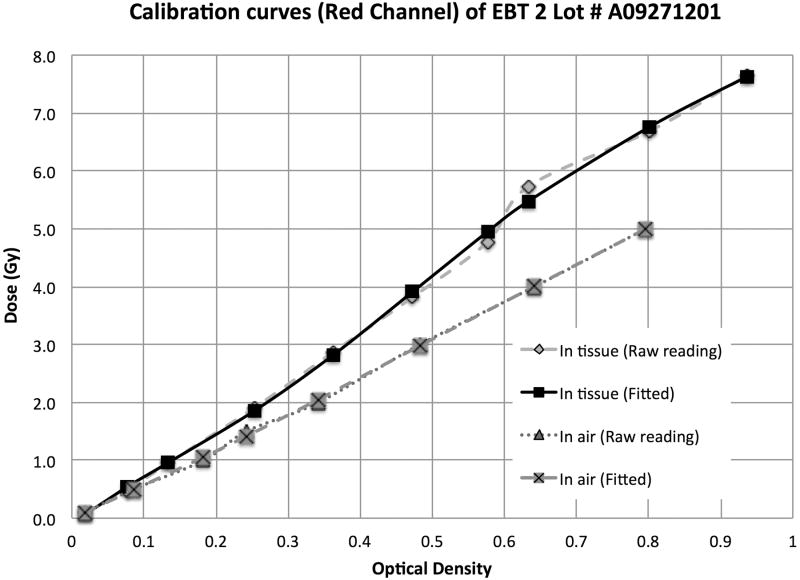
EBT-2 Gafchromic film ((International Specialty Products, Wayne, NJ) was used for these experiments. This film works well for megavoltage x-ray beam dosimetry, has a high spatial resolution and importantly a negligible energy dependence.(Arjomandy et al. 2010) The films were therefore calibrated up to 8 Gy for the 137Cs irradiator in air, and using 1 cm of tissue-equivalent build up and backscattering material. The films were placed perpendicular to the beam axis at the irradiation position P3, under static irradiation, with correction for transfer time error. Calibration curve fits are presented in Fig. 4 for dose to water measured in air and dose to water measured in 1 cm tissue-equivalent material, respectively, calculated from the dose rate of the 137Cs irradiator at the measurement point and applying a tissue attenuation correction of 4.5%/cm.
Figure 4.
H-D curves calibrated in air and in tissue (1 cm build up and 1 cm backscattering) for the 137Cs irradiator from 0 to 8 Gy.
Dose mapping of the irradiation cavity
Irradiation position P3 was used with a support table (15 cm high) that has been indexed to the turntable to allow for a unique support table position using three index holes on the turntable that are 120 degrees apart, as such some limited scattering effects of the support table influenced the measurements. A prescribed dose of 5 Gy in air was used to measure the isodose curves along the horizontal and vertical planes under rotation irradiation.
As per a previously published film dosimetry protocol (Hardcastle et al. 2011), films were scanned 36 hours post-irradiation to minimize the optical density fluctuation related to film self development. During rotation, the film geometry will be different compared to the static settings. Therefore, the measured dose was normalized to the dose at the isocenter (turntable rotation center), as this part of the film should remain static and thus represent the dose to water measured in air (film placed on Styrofoam support).
Dose distribution within subjects during rotation irradiation
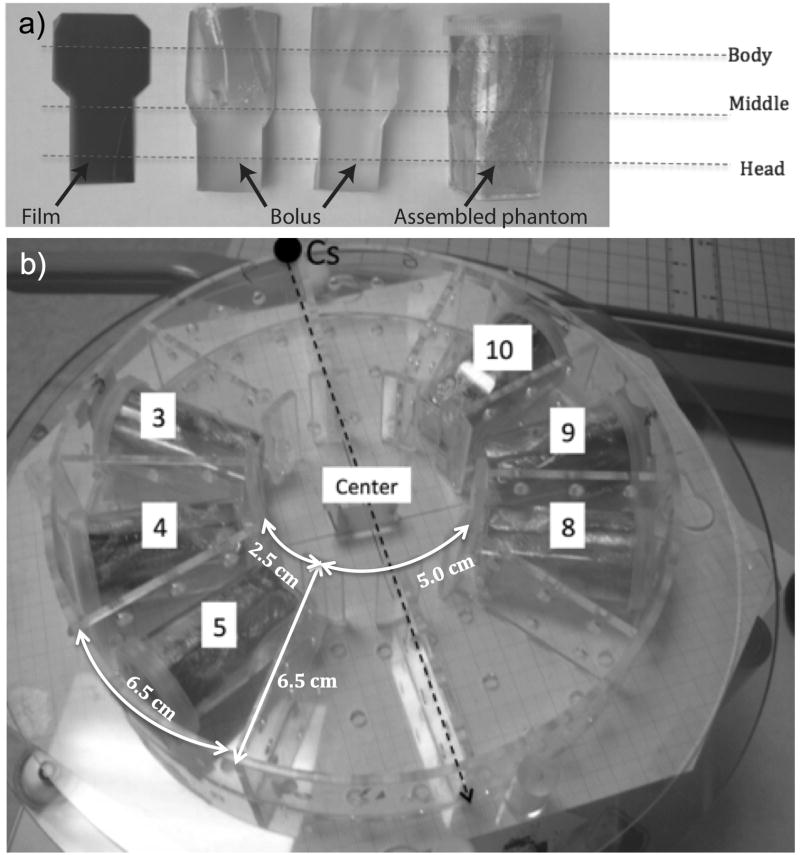
In order to measure the dose and dose distribution within subjects, a set of tissue-equivalent small animal phantoms were constructed, as illustrated in Fig. 5a. The phantom can be rotated to align the film with sagittal (vertical) or coronal (horizontal) planes according to experimental requirements.
Figure 5.
a) The small animal phantoms consisted of two pieces of half-round tissue-equivalent bolus material, a plastic holder, and a piece of EBT Gafchromic film sandwiched between the bolus pieces. This approximately resembled a head of size 2×2×2 cm, attached to a body 3.5 cm long and 3 cm in diameter. b) Irradiation jig loaded with phantoms in the recommended irradiation positions with respect to the source position.
These small animal phantoms were then loaded into a round Plexiglas jig (the dosimetric effect of which is henceforth referred to as the jig factor) that was then placed on the irradiator turntable (Fig. 5b). This jig has a diameter of 215.9 mm (8.5 inches), all the Plexiglas walls have a thickness of 3 mm, with a density of 1.18 g/cm3 and specific dimensions that are further explained in Fig. 5b. For each experiment the measurements were performed twice, first with the film phantoms aligned horizontally and then subsequently aligned vertically.
Proposed irradiation protocol for increased dose homogeneity
This phantom setup was used to evaluate the dosimetric accuracy and dose homogeneity of whole-body irradiation delivered using the conventional rotation irradiation method (CRIM) as proposed by the vendor. The CRIM was then compared with an irradiation protocol that was hypothesized to improve dose homogeneity between subjects receiving whole-body irradiation. These comparisons were performed for two different dose levels, 2.2 Gy and 5 Gy. The proposed protocol investigated was Half-dose Delivery with Opposite Re-setup, Rotation Irradiation Method (HDOR-RIM). The details of the irradiation protocol are given in a standard operating procedure available as Supplementary material. A Half-dose Delivery with Opposite Re-setup static irradiation method was also investigated, however, the lack of turntable rotation led to large deviations in dose between subjects (data not shown) and therefore, this option was not further explored. The main difference between HDOR-RIM and CRIM is that the jig with the irradiation subjects is rotated 180° after half of the intended dose delivery time. Setup uncertainty due to rotation of the jig on the support table is reduced, since the jig is indexed to the support table using diametrically opposed index holes and is fixed to the support table using neural nylon screws. In order to turn the jig these screws are loosened and the jig is carefully lifted off the support table, rotated by 180° and refastened to the support table. Note that the support table in turn is indexed uniquely to the irradiator turntable as described above.
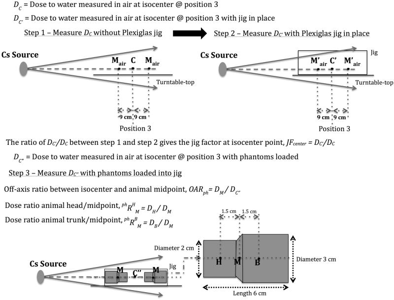
A dosimetry formalism is also proposed that can be used for HDOR-RIM aimed to achieve a higher dosimetric accuracy when calculating the irradiation time. This formalism is further explained by the illustrations provided in Fig. 6.
Figure 6.
Detailed description of the suggested HDOR-RIM dosimetry formalism and measurements needed to obtain the jig factor and off-axis ratio. This along with Equations 1 through 9 and the following notation will allow the user to perform any necessary dose calculations for this protocol. : Dose rate to water measured in air at isocenter point C without irradiation jig present. DM: Dose to water in phantom at position M. DH: Dose to water in phantom at position H. DB: Dose to water in phantom at position B. : Dose ratio between point H and point M in phantom. . JFcenter: Jig Factor, measured at isocenter with Gafchromic film comparing the dose with or without the jig.
DC is the dose to water measured in air at the calibration point, C, which corresponds to the center position of the turn table, i.e. the point about which the turn table rotates, either P1, P2, or P3. DC′ is the dose to water measured in air at the calibration point with the jig in place, as such the jig factor, JFcenter, at the calibration point is given by JFcenter = DC′/DC. Further, DC″ is the dose to water measured in air at the calibration point with the film phantoms loaded. The off-axis ratio between the calibration point, C, and animal (or phantom) midpoint, M, is measured for the presented irradiation setup and is defined as OARph = DM/DC″.
Based on this the irradiation time can be obtained using the following equations, where the dose to water at the midpoint in the phantom, M, can be calculated according to:
| (1) |
where DC″ = DC′ (1 − AF) and AF is the mean attenuation factor based on the number of animals loaded, as defined above. The point doses DH and DB subsequently can be calculated using:
| (2) |
and
| (3) |
where is the dose ratio between animal head/midpoint and the dose ratio between animal trunk/midpoint.
It follows from Equation 1 and the definition of the jig factor, JFcenter, that the dose to the midpoint of the animal, DM, can be expressed in terms of the dose to water measured in air at the calibration point, DC, as follows:
| (4) |
Equation 4 can be inverted to yield the calculated dose at the calibration point, , needed to achieve the desired prescribed dose, DM, at the midpoint of the animal:
| (5) |
As the dose can be prescribed to either points M, H, or B, the calculated dose at the calibration point, , is then given by either:
| (6) |
| (7) |
| (8) |
The total irradiation time is then obtained using:
| (9) |
where is the calculated dose to water at the calibration point C based on the dose prescribed to either point M, H, or B and is the dose rate to water measured in air at the calibration point. Since the expected dose at the turn table rotation center (calibration point) is calculated based on the dose prescribed to a point within the irradiation subject, a dosimeter such as a TLD chip or a OSL dosimeter, can be placed at the center of the irradiation jig to obtain a quality control measurement of the dose delivered during irradiation.
A spreadsheet that can be used for calculating the irradiation time is provided as supplementary material, where the input required by the user is the number of animals loaded into the jig, approximate size of the animals, prescribed dose to either the midpoint, body or head of the animal, the current activity of the 137Cs source given in Curie (or the dose rate to water in Gy/min if this is known). If the irradiation jig or loading of the animals differ significantly from the one described in this paper then the values of JFcenter, OARph, , and would have to be measured for the specific jig setup.
Verification experiments for dose distribution between and within subjects
To validate the proposed HDOR dosimetry protocols, two verification experiments were performed, a fan-view EBT film measurement in air and EBT film in phantom dose distribution measurements using the phantoms described in Fig. 5a.
For the fan-view experiment two 108° arc film strips were set up horizontally on the left and right side of the irradiation cavity, 5 cm above the turntable, which was placed at position P3. The films supported by Styrofoam blocks were irradiated to 5 Gy to the isocenter point, rotating the turntable 180° after the first half of irradiation as per the HDOR protocol.
To evaluate the dose distribution within subjects 6 film phantoms were placed symmetrically in the left and right side inserts of the Plexiglas jig as well as a piece of film measuring the dose in air at the jig isocenter. The subjects were then irradiated to 2.2 Gy or 5 Gy (prescribed to the middle of the film phantoms) using CRIM and HDOR-RIM. The EBT film calibration curves presented in Fig. 4 were used to calculate the delivered doses based on the exposed film phantoms.
Results
Simulation of SSD change due to turntable rotation
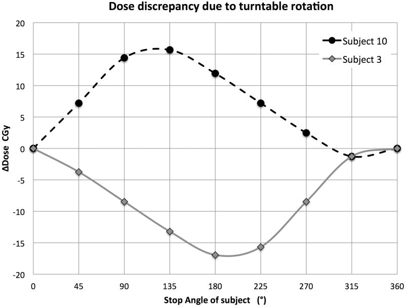
Fig. 7 illustrates the change in subject positions from a 108° turntable rotation. The extreme dose discrepancy scenario was simulated for subjects #3 and #10 by simulating their SSDs through one full rotation in steps of 45°, normalized to the dose at the rotation isocenter, i.e. the point with no change in SSD. Fig. 8 shows the expected variation in dose at the animal midpoint as a function of table stop angle, if a full rotation is not carried out when the table is placed at position P3. Of course for positions P1 and P2 this effect is even more pronounced, as they are closer to the source (data not shown).
Figure 7.
The change in subject positions from a 108° turntable rotation. Subjects that were in the hotter area (#1, #2, #3) have now moved into the colder area, while some of the subjects in colder area (#8, #9, #10) have now moved into the hotter area.
Figure 8.
Absolute dose discrepancy for subject #3 and #10 in one rotation cycle due to SSD change. Simulation conditions: Turntable at position P3, dose rate = 2.326 Gy/min, rotation speed = 4 cycles/min, mean SSD = 19.3 cm (range: 13.3 cm ∼ 25.8 cm). The maximum over dosage of 0.24 Gy for subject #10 occurs at the stopping angles between 90° to 135°, and the maximum under dosage of subject #3 of 0.24 Gy occurs at stopping angles between 180° and 225°. The dose discrepancy for the other subjects will be somewhere in between these two extremes.
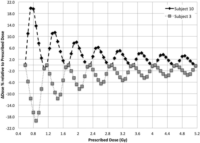
Notably, this dose discrepancy will cancel out at one full rotation, and importantly this means that the magnitude of the discrepancy will not increase with more table rotations, so the relative dose discrepancy decreases as the prescribed dose increases. This can be confirmed from Fig. 9 where the same simulation is extended to multiple turntable rotations, starting after one full rotation since the relative dose difference within the first rotation would be very large.
Figure 9.
Relative dose discrepancy simulated over multiple table rotations up to a prescribed dose of 5.2 Gy, starting after one full rotation.
Hence, with higher prescription dose and thus more rotation cycles, the relative dose discrepancy due to turntable rotation will be reduced. The maximum dose discrepancies would be approximately 8% to 20% for a prescribed dose < 3 Gy and would decrease to within ±5% for prescribed doses > 5 Gy.
Combined effects of SSD change and change in attenuation thickness
Combining the dose deviation from SSD change and change in attenuation thickness in quadrature leads to a considerable dose variability between subjects, for example approximately 14% for a prescription dose of 2 Gy. As presented in Table 1, where the deviation due to the change in SSD and attenuation thickness have been combined in quadrature, the overall variability in dose decreases as the prescribed dose increases.
Table 1.
Relative dose deviation based on the irradiator turntable rotation.
| Prescribed dose (Gy) | 1.0 | 2.0 | 3.0 | 5.2 |
|---|---|---|---|---|
| ΔD% due to SSD | ±20% | ±11.7% | ±7.4% | ±4% |
| ΔD% due to attenuation | ±14% | ±7.2% | ±5% | ±2.8% |
| Total ΔD% | ±24% | ±14% | ±9% | ±5% |
Dose mapping of the irradiation cavity during CRIM
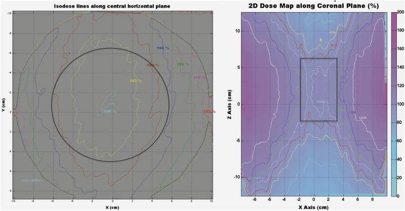
The horizontally and vertically placed EBT films were irradiated to a prescribed dose of 2.2 Gy and 5 Gy to the center of the film, delivered using the CRIM protocol. Fig. 10 describes the regions within the irradiation cavity with less than ± 5% variation in dose compared to the isocenter dose.
Figure 10.
Isodose curves showing the dose distribution horizontally and vertically throughout the irradiation cavity. Solid black lines represent the regions with a dosimetric uncertainty of less than ±5% compared to the isocenter dose, resulting in a circular region of 12 cm in diameter and a rectangular region of 5 cm × 8 cm for the horizontal and vertical planes, respectively.
Dosimetric characterization between subjects during HDOR-RIM
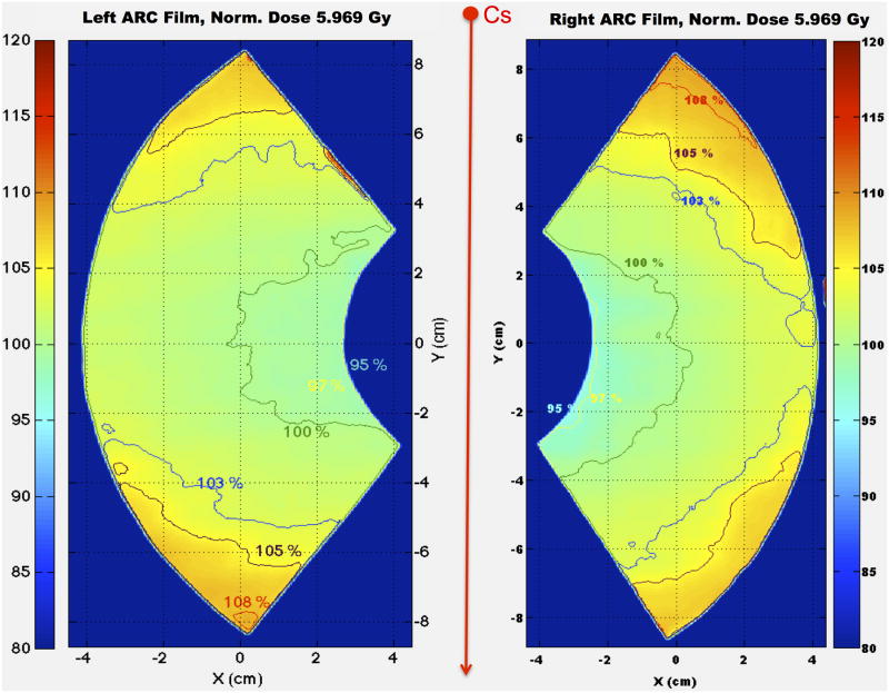
The two 108° fan-view arc EBT films (each of which covers three subject cages in the Plexiglas jig) were irradiated symmetrically on either side of the beam axis, 5 cm above the turntable as to mimic the middle dose planes of the subject cages. The dose was normalized to the point of the fan film corresponding to the center point of the middle cage in which subjects are placed. Isodose curves are presented in Fig. 11 showing similar dose distributions for the two films, with minimum dose measured at 95% and maximum dose at about 108%.
Figure 11.
Isodose curves showing the 2D relative dose distributions from the two arc films irradiated to 5 Gy to the rotation isocenter using the HDOR-RIM protocol.
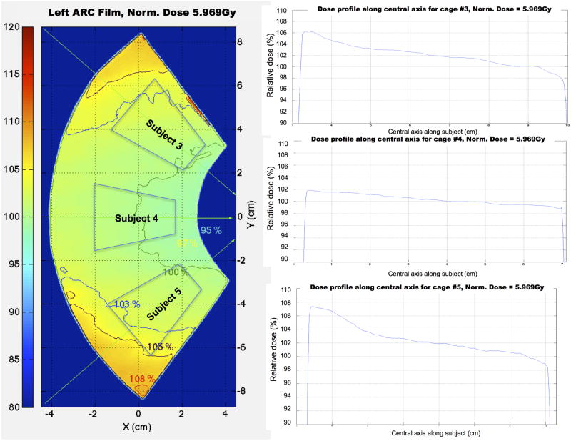
In Fig. 12 it is determined that based on these fan-view measurements, the dose profiles at the location where the subjects would be placed are within the range of 97% to 105% of the reference dose.
Figure 12.
Dose profiles along the central axis of three virtual subjects from the left fan-view film, showing that profiles are homogeneous especially for the middle subject.
Within subject dose characterization for the proposed HDOR-RIM protocol
The 6 film phantoms were loaded symmetrically in the Plexiglas jig and irradiated to a prescribed isocenter dose of either 2.2 Gy or 5 Gy.
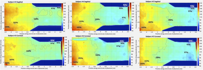
As presented in Fig. 13, the dose distribution is similar both in the horizontal and vertical planes for 3 different subjects when irradiated using the HDOR-RIM protocol. Given the “pie-shaped” cages in the Plexiglas jig, phantoms (as well as animals) are placed with the head facing towards the rotation isocenter in the jig (Fig. 5b). The thicker “body” part of the phantoms receive a slightly higher dose of between 100% to 105% and the “head” part of the phantoms receive a dose close to 98%, relative to the isocenter dose.
Figure 13.
2D dose distributions along the sagittal plane (upper row) and coronal plane (lower row) for subjects #3, #4 and #5, irradiated with the HDOR-RIM protocol to a prescribed dose of 5 Gy.
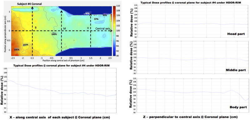
Using the dose distribution for subject #4 as an example, Fig. 14 illustrates the dose profiles measured throughout the phantom. Along the central x-axis, the relative dose gradually decreased from 105% to 98% from the body to the head of the subject. The transverse dose profiles at points B, M and H were homogenous showing good dose uniformity in these planes. By comparing the measured dose at the middle point of the subjects to that of the isocenter reference film, an average value and standard deviation was determined for the off-axis ratio, OARph, for the HDOR-RIM protocol measured at both 2.2 Gy and 5 Gy to be OARph = 1.075 ± 0.004. The jig factor, JFcenter, giving the ratio of the dose with and without the jig in place was measured to be 0.935 ± 0.003 for the current setup.
Figure 14.
Dose profile along the central x-axis and transverse lines through points B, M and H (body, middle and head) for subject #4, irradiated with the HDOR-RIM protocol to a prescribed dose of 5 Gy.
Within subject dose distribution comparing CRIM and HDOR-RIM
The same within phantom film dosimetry experiments as for the HDOR-RIM protocol described above were also carried out for the CRIM protocol, comparing the dose uniformity between these protocols.
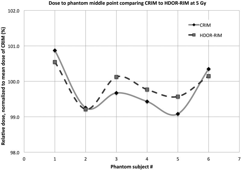
The dose to the middle phantom point M is presented as absolute and relative dose in Table 2 comparing the two protocols CRIM and HDOR-RIM at 2.2 Gy and at 5 Gy. From Table 2, it can be determined that there is a larger uncertainty in dose for 2.2 Gy dose (within ±5% for CRIM and ±3% of HDOR-RIM) compared to the 5 Gy dose (within ±1% for CRIM and ±0.7% for HDOR-RIM also illustrated in Fig. 15).
Table 2.
Doses to the middle point in subjects irradiated to a prescribed dose of either 2.2 Gy or 5 Gy with CRIM or HDOR-RIM. Subject # refers to the subject positions as shown in Fig. 2 and Fig. 8b. The doses are normalized to the average dose for all subjects irradiated with the CRIM protocol.
| Prescribed Dose = 2.2 Gy | DM (Gy) | DM (%) | ||
|---|---|---|---|---|
| Subject # | CRIM | HDOR-RIM | CRIM | HDOR-RIM |
| 3 | 2.185 | 2.151 | 104.5 | 102.9 |
| 4 (middle) | 2.056 | 2.093 | 98.4 | 100.1 |
| 5 | 2.061 | 2.090 | 98.6 | 100.0 |
| 8 | 2.040 | 2.064 | 97.6 | 98.8 |
| 9 (middle) | 2.005 | 2.077 | 95.9 | 99.4 |
| 10 | 2.191 | 2.145 | 104.8 | 102.6 |
| Mean | 2.090 | 2.103 | 100.0 | 100.6 |
| Prescribed Dose = 5 Gy | DM (Gy) | DM (%) | ||
| Subject # | CRIM | HDOR-RIM | CRIM | HDOR-RIM |
| 3 | 5.179 | 5.162 | 100.9 | 100.5 |
| 4 (middle) | 5.096 | 5.094 | 99.3 | 99.2 |
| 5 | 5.117 | 5.141 | 99.7 | 100.1 |
| 8 | 5.105 | 5.122 | 99.4 | 99.8 |
| 9 (middle) | 5.087 | 5.112 | 99.1 | 99.6 |
| 10 | 5.152 | 5.142 | 100.3 | 100.2 |
| Mean | 5.134 | 5.129 | 100.0 | 99.9 |
Figure 15.
The distribution of measured doses at the middle point of film phantoms comparing the CRIM and HDOR-RIM for a prescribed dose of 5 Gy.
Discussion
A dosimetry formalism and irradiation protocol are presented that can increase the dose homogeneity for whole-body small animal irradiation using the JL Shepard Mark I-68A 137Cs irradiator, especially if lower prescription doses are employed.
The region of homogeneous irradiation (100% ± 5%) was measured to be approximately 12 cm in diameter and 8 cm high for this irradiator using film dosimetry (Fig. 10). This region was found to be smaller than the region suggested by the vendor (14 cm × 18 cm) but comparable to the 10 cm × 12 cm region reported in a previously published dosimetric characterization of a 137Cs irradiator.(Brady et al. 2009)
Compared to the conventional irradiation protocol, using the HDOR-RIM protocol incorporates corrections for the off-axis ratio from subject midpoint to the rotation isocenter and an effective tissue attenuation thickness, dependent on the number of animals loaded into the jig. These factors are incorporated into the dosimetry formalism of the proposed HDOR-RIM irradiation protocol, and as such using the CRIM protocol would mean ignoring these correction factors.
With respect to the accuracy and homogeneity of the dose delivered to whole-body irradiated subjects it was found that for prescribed doses < 5 Gy the vendor-based CRIM protocol could result in dosimetric deviations of more than ± 5% throughout the subjects. Thus, the main usefulness of the proposed HDOR-RIM and dosimetry formalism, ensuring a variation in dose of less than 3% between subjects, will be for whole-body irradiation experiments where the dose-response is steep, requiring homogeneous radiation delivery.
A limitation of this study and the proposed protocol is of course that the assumed shape of the irradiation subjects, for which the film measurements were taken, may not represent the full range of animals to be irradiated. There can be considerable size variation among small animals, such as between mice and rats that could alter the applied dosimetric corrections somewhat. The impact on the attenuation corrections can, however, be taken into account by specifying the average subject dimensions in the calculation spreadsheet when computing the attenuation correction factor. It should be noted though that a change in animal size affects the CRIM protocol to an even larger extent, since no size corrections are applied. Substantial variation in animal size will also affect the jig factor (JFcenter) and off-axis ratio (OARph) corrections and ideally these factors should also be measured to take this change into account.
These data (Table 2) indicate that using 6 subjects will lead to dose homogeneity between animals of better than 3%. This is however, the maximum number of animals that will allow for this increased homogeneity with the current geometrical setup. If fewer than 6 subjects are irradiated they should be irradiated in pairs that are placed diametrically opposed. If irradiating 2 subjects they should be placed in positions #4 and #9, while 4 subjects should be placed in positions #3, #5, #8, and #10, and 6 subjects should be placed in positions #3, #4, #5, #8, #9, and #10 (as can be compared to Fig. 2 and Fig. 5b), thus avoiding the hottest and coldest sectors, that are closest and furthest from the source.
Based on the results presented in this study, using the proposed HDOR-RIM protocol and dosimetry formalism is recommended, even for higher radiation doses where the CRIM would provide sufficient dose homogeneity. Mainly because the dosimetry formalism for the HDOR-RIM protocol estimates the dose to water, takes off-axis correction and variation in attenuation thickness into account, resulting in a delivered dose that is closer to the actual prescribed dose. Since part of the dosimetry formalism is geometry dependent, the OARph and JFcenter would need to be determined for the specific irradiator and jig setup if these differ substantially from the setup and irradiator used in this study, although these factors should still be valid for a similar irradiation setup. As long as mice are used for the experiments, use of the presented irradiation protocol and measured factors is recommended, especially since size corrections for attenuation can be applied when calculating the irradiation time. If rats are to be used, however, measuring the OARph and JFcenter for the specific setup is recommended, given that rats are too large to fit in the jig used in this study as well as to determine the appropriate values for , and .
Supplementary Material
Acknowledgments
The authors would like to thank the anonymous reviewers for their helpful and constructive comments that have improved the quality and presentation of the manuscript. This work has been supported in part by grant U19AI091175 from the United States National Institutes of Health (NIH). The contents are solely the responsibility of the authors and do not necessarily represent the official views of the NIH.
Biography
Dr. Patrik Brodin holds a MSc degree in Medical Physics from Lund University in Sweden and a PhD degree in Medical Physics from Copenhagen University in Denmark. Dr. Brodin is currently working as a postdoctoral researcher at the Albert Einstein College of Medicine in New York where he is focusing on studying radiation-driven immunotherapy, risk-adaptive radiation therapy and countermeasures for effects of acute radiation exposure.

Footnotes
Conflict of interest statement: The authors have no conflicts of interest to declare in regards to this work.
References
- Arjomandy B, Tailor R, Anand A, Sahoo N, Gillin M, Prado K, Vicic M. Energy dependence and dose response of gafchromic ebt2 film over a wide range of photon, electron, and proton beam energies. Medical physics. 2010;37:1942–7. doi: 10.1118/1.3373523. [DOI] [PubMed] [Google Scholar]
- Bazalova M, Nelson G, Noll JM, Graves EE. Modality comparison for small animal radiotherapy: A simulation study. Medical physics. 2014;41:011710. doi: 10.1118/1.4842415. [DOI] [PMC free article] [PubMed] [Google Scholar]
- Brady SL, Toncheva G, Dewhirst MW, Yoshizumi TT. Characterization of a 137cs irradiator from a new perspective with modern dosimetric tools. Health physics. 2009;97:195–205. doi: 10.1097/HP.0b013e3181a9bd42. [DOI] [PMC free article] [PubMed] [Google Scholar]
- Brady SL, Yoshizumi TT, Anderson-Evans C, Nguyen G. Isodose curve mappings measured while undergoing rotation for quality assurance testing of a 137cs irradiator. Health physics. 2012;102(Suppl 1):S8–12. doi: 10.1097/HP.0b013e31823c9671. [DOI] [PMC free article] [PubMed] [Google Scholar]
- Cummins DO, Delaney CF. Design studies for a cs-137 irradiator. The International journal of applied radiation and isotopes. 1961;10:106–11. doi: 10.1016/0020-708x(61)90106-5. [DOI] [PubMed] [Google Scholar]
- Hardcastle N, Basavatia A, Bayliss A, Tome WA. High dose per fraction dosimetry of small fields with gafchromic ebt2 film. Medical physics. 2011;38:4081–5. doi: 10.1118/1.3597834. [DOI] [PubMed] [Google Scholar]
- Hassan GM, Rabie N, Shousha HA, Ezzat M. Impact of beam quality q for 137cs on nk and nd,w for different types of ionization chambers. Applied Physics Research. 2011;3:115–121. [Google Scholar]
- International Commission on Radiation Units and Measurement, Quantitative concepts and dosimetry in radiobiology. 1979 Report no. 30. [Google Scholar]
- Kazi AM, MacVittie TJ, Lasio G, Lu W, Prado KL. The mcart radiation physics core: The quest for radiation dosimetry standardization. Health physics. 2014;106:97–105. doi: 10.1097/HP.0b013e3182a2a987. [DOI] [PMC free article] [PubMed] [Google Scholar]
- Minniti R, Seltzer SM. Calibration of a 137cs gamma-ray beam irradiator using large size chambers. Applied radiation and isotopes: including data, instrumentation and methods for use in agriculture, industry and medicine. 2007;65:401–6. doi: 10.1016/j.apradiso.2006.10.008. [DOI] [PubMed] [Google Scholar]
- Rodriguez ML, del Risco Reyna L, de Almeida CE. Study of the radiation field characteristics of a 137cs irradiator by monte carlo simulation. Health physics. 2003;85:433–7. doi: 10.1097/00004032-200310000-00007. [DOI] [PubMed] [Google Scholar]
- Wheatley BM, Jones JC, Sinclair TC. A caesium 137 beam therapy unit. I. Physical aspects. The British journal of radiology. 1960;33:251–7. doi: 10.1259/0007-1285-33-388-251. [DOI] [PubMed] [Google Scholar]
- Yoshizumi T, Brady SL, Robbins ME, Bourland JD. Specific issues in small animal dosimetry and irradiator calibration. International journal of radiation biology. 2011;87:1001–10. doi: 10.3109/09553002.2011.556178. [DOI] [PMC free article] [PubMed] [Google Scholar]
- Zoetelief J, Broerse JJ, Davies RW, Octave-Prignot M, Rezvani M, Vergara JC, Toni MP. Protocol for x-ray dosimetry in radiobiology. International journal of radiation biology. 2001;77:817–35. doi: 10.1080/09553000110050605. [DOI] [PubMed] [Google Scholar]
Associated Data
This section collects any data citations, data availability statements, or supplementary materials included in this article.


