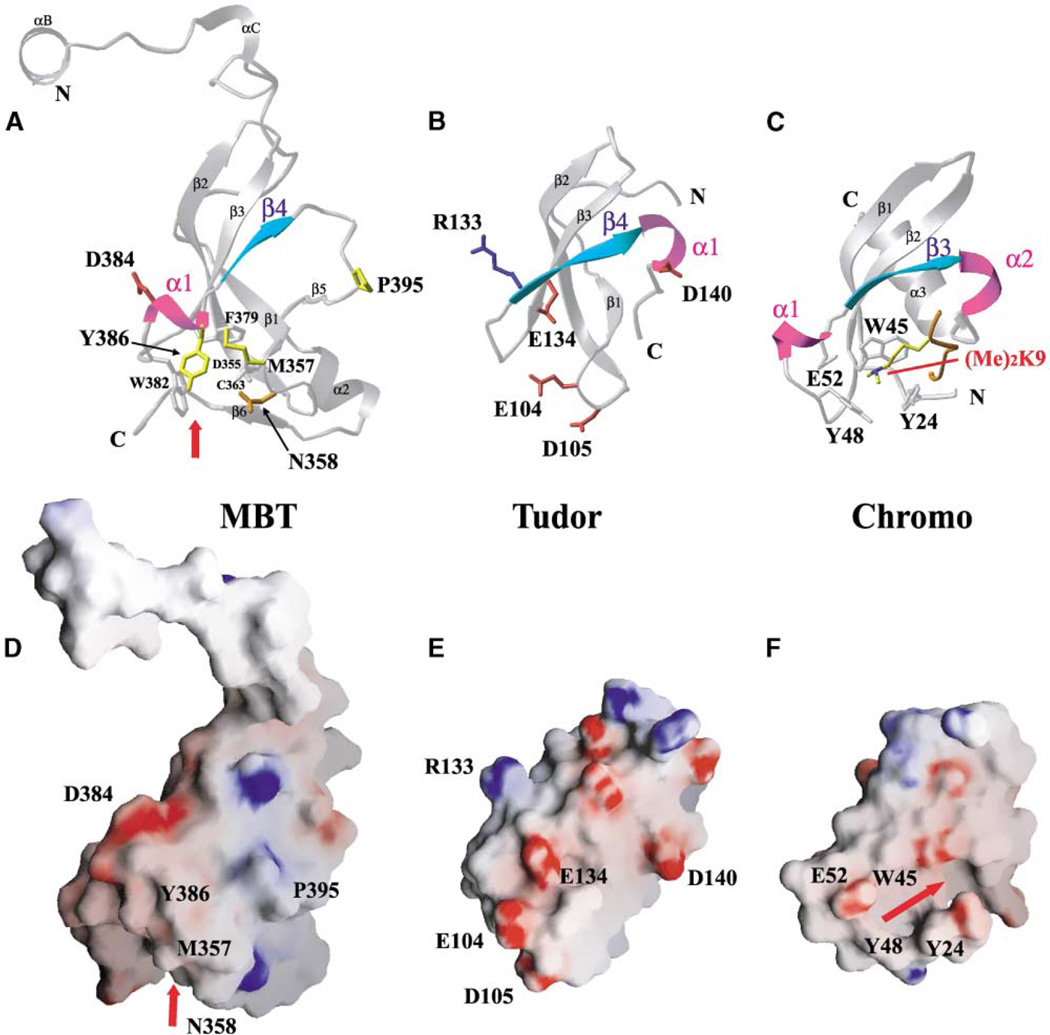
Figure 7. Structural Homology between the 3mbt β Subunit Core, Tudor Domain, and Chromodomain.
(A) Ribbon representation showing the β subunit core of the second repeat of the seleno-met 3mbt structure.
(B) Ribbon representation of the Tudor domain (Selenko et al., 2001). Note the difference in the position of the α1 helical turn between Tudor domain (B) and mbt repeat (A).
(C) Ribbon representation of the chromodomain of HP1 bound to a dimethylated lysine 9 histone H3 tail (Jacobs and Khorasanizadeh, 2002).
(D) Electrostatic surface representation of the second mbt repeat of the seleno-met 3mbt structure. Refer to Figure 2B for the electrostatic surface of the ligand binding cage.
(E) Electrostatic surface representation of the Tudor domain. Note the differences in surface charge distributions between the Tudor domain (E) and mbt repeat (D).
(F) Electrostatic surface representation of the chromodomain of HP1. Note the cavity and the aromatic cage that accommodates the histone H3 peptide tail and dimethylated lysine 9.
The secondary-structural elements of α1 and β4 (A and B) are colored magenta and cyan, respectively. Hydrophobic (yellow), positively charged (red), negatively charged (blue), and polar (orange) side chains are shown in the ball and stick representation for 3mbt in (A) and the Tudor domain in (B). Other related residues involved in the cage are indicated in silver for clarity. The electrostatic surface in 3mbt (D) and the Tudor domain (E) is colored as in Figures 2B and 2C. The red arrow indicates the location of the ligand binding cage in the mbt structure and the binding cavity for the histone H3 peptide tail in the chromodomain, respectively.

