Abstract
Quantitatively capturing developmental processes is crucial to derive mechanistic models and key to identify and describe mutant phenotypes. Here protocols are presented for preparing embryos and adult C. elegans animals for short- and long-term time-lapse microscopy and methods for tracking and quantification of developmental processes. The methods presented are all based on C. elegans strains available from the Caenorhabditis Genetics Center and on open-source software that can be easily implemented in any laboratory independently of the microscopy system used. A reconstruction of a 3D cell-shape model using the modelling software IMOD, manual tracking of fluorescently-labeled subcellular structures using the multi-purpose image analysis program Endrov, and an analysis of cortical contractile flow using PIVlab (Time-Resolved Digital Particle Image Velocimetry Tool for MATLAB) are shown. It is discussed how these methods can also be deployed to quantitatively capture other developmental processes in different models, e.g., cell tracking and lineage tracing, tracking of vesicle flow.
Keywords: Developmental Biology, Issue 106, quantitative biology, development, time-lapse microscopy, tracking, 3D modelling, embryogenesis, cortical flow
Introduction
With the steady improvements of fluorescent proteins, genome engineering, light microscopy, and computer soft- and hardware, it is now possible to record development of many model organisms at unprecedented spatio-temporal resolution. This allows researchers to ask questions that could not be addressed previously or to revisit known developmental processes in order to search for overlooked aspects. This progress has sparked the field of quantitative developmental biology, which aims at transforming qualitative, informal models into quantitative models by thorough measurements and statistical analyses.
Tracking cells and subcellular structures has made it possible to derive quantitative models of embryonic development, nervous system activity, or cell division1-12. By tracking cell division remnants during early development of the C. elegans embryo, we could recently reveal that they follow a stereotyped path and constitute important polarizing factors13,14.
Here, protocols are presented that make quantitative developmental biology approaches accessible for non-experts. The focus lies on three straight-forward, freely available tools that are implementable in any lab that has access to standard confocal microscopy and computers. These include a protocol to generate 3D cell shapes, a protocol to track cell division remnants, and a protocol to quantitatively describe cortical actomyosin dynamics. The nematode C. elegans is used as an exemplary case, however, the methods and tools discussed here are suited for a variety of questions in other biological models, e.g., cultured cells, tissue explants, organoids or spheroids, other embryos, etc.
Generally, some of the analyses shown here can also be performed with the popular open source tool ImageJ (http://imagej.nih.gov/ij/docs/index.html; or FIJI, the ‘batteries included’ version of ImageJ, http://fiji.sc/Fiji) for which many plugins for different quantitative analyses are available. However, the programs discussed here are designed to tackle specific problems.
Firstly, IMOD, an image processing, modeling and display suite can be used for 3D reconstructions of serial sections from electron or light microscopy15. IMOD also contains tools for viewing the 3D data from any orientation. Secondly, Endrov, a Java program designed to perform image analysis, data processing, and annotation of networks or tracks (among others) on the basis of an extended plugin architecture, with ImageJ plugin compatibility16. It contains over 140 image-processing operations and an extensible user interface in which model and raw data are displayed separately. Its source code can be found at https://github.com/mahogny/Endrov. Thirdly, PIVlab, a MATLAB tool for digital particle image velocimetry that allows the user to quantitatively and qualitatively analyze particle flow fields17. The use of this programs requires a MATLAB license that includes the Image Processing Toolbox (http://mathworks.com). PIVlab is a program designed to quantitatively describe flow. It calculates the velocity distribution, magnitude, vorticity, divergence, or shear within image pairs or series. For this, it cross-correlates small areas of images (called ‘passes’ in the protocol section) of an image pair to derive the most probable particle displacement. This cross-correlation yields a correlation matrix that can be analyzed in the space or frequency domain using either direct cross-correlation or a fast Fourier transformation (FFT), respectively.
The equipment used here is an inverted microscope equipped with a Nipkow ('spinning') disc, an EMCCD, 488 and 561 nm standard solid-state lasers, and 20x air or 40x or 60x plan/apochromat oil- or water-immersion objectives. However, it is also possible to perform time-lapse imaging with other imaging modalities, e.g., point-, line- or sheet-scanning laser-based microscopy, multi-photon microscopy, as well as epi-fluorescence microscopy combined with deconvolution or structured illumination. The advantage of using a Nipkow disc system is the extremely fast image acquisition, especially if a streaming mode (continuous movement and scanning of the object in the z dimension) is available. In addition, to improve resolution, a 1.5-fold magnifying extender in front of the EMCCD can be used.
Protocol
1. Preparation of C. elegans Embryos for Time-lapse Microscopy using Microbeads
Transfer gravid adult worms by using a worm pick (platinum wire) into a drop of M9 buffer and clean off bacteria by first vigorously agitating and then transferring each worm to an adjacent drop of M9 using an eye lash mounted onto a tooth pick/pipette tip or use a pointed glass capillary.
Dilute the dispersion containing the 20 µm diameter polystyrene beads 10-fold in M9 buffer (1 L M9 buffer contains 3 g KH2PO4, 6 g Na2HPO4, 5 g NaCl, and, after autoclaving (20 min, 120 °C), add an additional 1 ml of a 1 M MgSO4 solution).
Make a mouth pipette from any type of thin glass capillary (e.g., melting point capillaries or capillaries used to pull injection needles), a roughly 0.5 m long piece of rubber, silicone or similar material tubing (ideally transparent), a 200 µl pipette tip, the lid of a 200 µl PCR tube, a hydrophobic filter for small syringes (e.g., a 0.2-0.45 µm pore size and 15-50 mm diameter Nylon, PTFE or similar material filter), and a 1000 µl pipette tip. This type of mouth pipette ensures that no biological material can get in contact with the experimenter.
Assemble the pipette by inserting the 200 µl pipette tip with the tip first into the tubing and plug it with the lid of a PCR tube which has a central perforation that matches the diameter of the capillary used. A very pointed awl or preparation needle can be used to generate the perforation.
Draw a thin capillary and insert it into the perforation. Insert the filter into the other end of the tubing and insert a 1000 µl pipette tip as mouth piece (Figure 1).
Dissect gravid adults by cutting worms transversely at the vulva with a clean razor blade or scalpel. NOTE: Usually, many embryos will be expulsed after cutting. However, if early embryos are needed, they sometimes have to be released from the carcass using an eye lash or pointed needle.
Pipette one drop of the diluted polystyrene bead dispersion (~4 µl) onto a 24x60 mm cover glass and transfer embryos into this drop using the mouth pipette.
Carefully place a small (e.g., 18x18 or 20x20 mm) cover glass on top of the drop and make sure the drop has fully spread out. NOTE: The drop should also be small enough not to touch the edges of the small cover glass.
Seal the mount with liquefied vaseline. Add a drop of immersion oil on the 24x60 mm cover slip side and proceed to the 'Time-lapse Microscopy' section.
2. Preparation of Adult C. elegans Animals for Time-lapse Microscopy using Nanobeads
NOTE: In general, the protocol for mounting adult animals is an adaptation of the protocol from ref. 18. With this protocol, it is possible to perform long-term time-lapse confocal microscopy of adult animals.
Prepare a 1.5% (w/v) agarose solution in M9 buffer, boil (1 min, 100 °C in water bath or microwave). The use of higher concentrations of agarose is not recommended since this can lead to extrusion of the intestine and/or parts of the gonad.
Stick down 2-3 layers of tape onto two microscope slides each. Place a slide without tape between the two slides with tape.
Use a pipette tip and place one drop of the hot agarose solution in the center of the middle slide. Quickly place another slide onto the drop so that it is supported by the tape layers on each side. This will create a round and flat agar pad of around 10 mm diameter.
Put a drop of 100 nm bead solution (undiluted, which is 2.6% (w/v)) onto the pad. Transfer 1-10 cleaned adult worms into the drop with a worm pick. Seal with 18x18 mm cover glass and vaseline as explained in Protocol 1.
3. Time-lapse microscopy
Put a drop of immersion oil onto the microscope slide or the cover glass sandwich. Use brightfield at low magnification (5x or 10x lenses) to locate the sample. NOTE: Limit the exposure to blue light as much as possible (in particular for C. elegans embryos), e.g., do not use epi-fluorescence microscopy to find/focus the specimen but use brightfield instead.
Change to higher magnification (40x or 60x objectives), bring the sample into focus (either central plane or top/bottom planes of the sample, depending on the acquisition software).
Set the sampling intervals to 30 planes at 1 µm spacing recorded every 1min. In case an automated xy- or xyz-stage is available, multiple spots can be recorded in one session. Switch to fluorescence imaging and check the focus again. NOTE: Try to avoid using high laser powers, rather use slightly longer exposure times at very low intensities. Measure acquired images right away, either in the image acquisition program or in ImageJ to avoid saturation, which crops the dynamics range and also means excessive radiation exposure.
Start recording the time-lapse series. NOTE: To exclude analyzing artifacts, start with long (3-10 min) time intervals between sample scanning and gradually increase temporal sampling to the desired intervals. Developmental timing as well as end points in both cases should be similar when performing a statistical analysis. Moreover, it is often necessary to assess phototoxicity and survival rates. Therefore, recover specimen from the mount after long-term time-lapse microscopy and check whether they continue to develop/live.
4. Reconstructing a 3D Cell Shape model with IMOD
NOTE: IMOD software is available from the IMOD web page: http://bio3d.colorado.edu/imod/. Installation of the software is described there. When using Windows OS, a Unix toolkit has to be installed, which can also be found as a package on the IMOD webpage. Moreover, there is an excellently compiled 3dmod introduction available on the IMOD webpage (http://bio3d.colorado.edu/imod/doc/3dmodguide.html).
Open the Unix shell and type in "imod". The IMOD window will open. Select the file with the raw data (ideally a stacked tif or similar) from which to generate a 3D model.
Locate the bottom and top of the objects in the ZaP window by using the information window (up&down scrolling tool).
Start tracing the cell outlines. Importantly, ensure that each cell is one object. Begin with the top plane of each cell and create the first contour there using the information window. Scroll down in z and create a new contour for each z-plane.
Do the same for as many cells as needed to model in 3D. Do not forget to create a new object when starting with a new cell. NOTE: There are many different ways for contour tracing and several helpful plugins. Please visit the IMOD webpage and online tutorials for details. In the case shown here, the default setting has been used.
Open the "Model View" window to inspect the objects and their contours.
In the "Model View" toolbar choose "Edit" -"Objects". The respective editing window will open.
To model cells as filled and closed objects, choose "Mesh" as "Draw Data Type" and "Fill" as "Drawing Style". Click on "Meshing" in the scrollable selection at the lower left of the window. Check the option "Cap" in the selection at the lower right. Check as many objects as necessary and click "Mesh All". The program will generate solid objects from the stacks of contours. The z-sampling factor can be adjusted by changing "Z-scale" in the "View" window.
Move/rotate the 3D object ("Edit" - "View") and save snapshots or movies ("File" -"Snap Tiff As ..." or "Movie/Montage").
5. Tracking Fluorescently Labeled Structures with Endrov
NOTE: In order to track cell division remnants, use a strain with a nuclear or plasma membrane marker for cell identification (e.g., H2B, PH-PLC-d1) and a cell division remnant marker (e.g., NMY-2, ZEN-4). The nuclear or plasma membrane marker is important to determine which cell inherits the cell division remnant.
For fast loading and ease of use, the raw data has to be converted to a tiff file (e.g., in ImageJ). Next, open Endrov and load the file to be analysed by choosing the "Load file" option from the file menu. Click on the "2D viewer" icon on the toolbar.
Adjust the histogram by clicking on the "Fit range" icon (the blue icon at the bottom right corner of the Endrov screen). Set the XYZ-resolution by going to "Data" -"filename"-"Imageset" -"Channel"-"Set XYZ-resolution". Type in values for X, Y, and Z, e.g., 5, 5, 1 if X and Y resolution is 0.2 µm and sample every 1 µm in Z.
For annotating the nuclei, move to the plane of interest and click on "2D viewer". Select "Lineage" from the dropdown menu and choose "New lineage".
By clicking and dragging on the nucleus, it can be marked. To name the nucleus, right click and choose "Rename particle" from the dropdown menu. To increase or decrease the diameter of the circle, drag the arrow icon that appears on the left of the marked circle. To mark the central plane of the nucleus, click on the right icon. When using a plasma membrane marker, a large sphere can be drawn that will cover most of the cell.
To proceed in time and plane, choose the "Frame" and "Z" options at the bottom toolbar. After going to the next time point, adjust the position or size of the circle that marks the nucleus accordingly. Repeat this until the tracked cell divides.
When there is a cell division, mark the daughter nuclei and switch to "Lineage viewer". This can be selected by clicking on the "Windows" icon on the top toolbar. Mark all three nuclei simultaneously, go to the "Lineage" option in the top toolbar and select "Associate parent".
When cell tracking is finished, switch to the channel marking the cell division remnant for tracking. To switch channels, click on the file name on the bottom left corner of the toolbar. The cell division remnant (or any other structure) can be tracked as described above for the nucleus.
When returning to the software after closing, it is necessary to go to "2D Viewer" -"Lineage"-"Edit" and to click on the lineage number that will be edited.
6. Analyzing Cortical Actomyosin Flow with PIVlab
NOTE: PIVlab is a freely available software from: http://pivlab.blogspot.de/; it can be invoked from within the Matlab command line environment by typing PIVlab_GUI. When working with PIVlab, it is recommended to save the image series in a separate folder.
Start a new session from "File menu". Load the image files by clicking the "Load images" button.
Select the sequencing style 1-2, 2-3, ... and navigate to the directory that contains the sequence of desired images. Select the images and click on the "Add" button and import.
Go to "Analyses settings" and select "Exclusions (ROI,Mask)". Alternatively, press "Ctrl + E". Use the button "Draw mask(s) for current frame" to inactivate the undesired part of the image/s (i.e., area outside embryo).
Select "PIV settings" from the "Analyses settings" menu. Alternatively, press "Ctrl + S". Choose "FFT window deformation" as the desired PIV algorithm. NOTE: Fast Fourier transformation (FFT) reduces the computational cost but is only recommended the signal is well above noise and if the displacement of the particles studied does not exceed half the pass area analyzed (see 6.5).
Enter the following values for the three passes, which are the area of interrogation for intensity cross correlation between subsequent images: Pass 1: Interrogation area of 64 pixels with a step of 32. Pass 2: Interrogation area of 32 pixels with a step of 16. Select "linear" from the Window deformation drop down menu. Choose Gaussian 2*3-point method for sub-pixel displacement estimation.
Select "Analyze!" from Analysis menu and use the button "Analyze all frames" to begin an analysis.
For post processing select "Vector validation" from "Post processing" menu and set the standard deviation (Stdev) filter threshold to 7 and apply to all frames.
Choose "Derive parameters/ modify data" from "Plot" menu. Select "Vectors [px/frame]" from dropdown menu. Adjust the smoothness of vectors and high pass filter and apply to all frames.
To calculate mean vectors of all frames, set the "Used frames" to 1:end and click on "Calculate mean vectors" button.
Representative Results
By using protocols 2, 3, and 4, time-lapse imaging of gonads in wild type C. elegans adults is performed (strain OD58 (unc-119(ed3) III; ltIs38[pAA1; pie-1::GFP::PH(PLC1delta1) + unc-119(+)]), expressing a membrane marker from a germline promoter). Focusing on the turn of the gonad, a 3D model of the germ cells is generated from the microscopy data (Figure 2). This model allows to analyze changes in cell size while the cells transit form the distal to the proximal arm, reveals the organization of the rachis and the size of the contacts of individual cells to the rachis (see also http://www.wormatlas.org/hermaphrodite/germ%20line/Germframeset.html).
Next, protocols 1, 3, and 5 are used to perform long-term time-lapse microscopy of C. elegans embryos (strain CHP52 which is a cross of strain RW10226 (unc-119(ed3) III; itIs37[pie-1p::mCherry::H2B::pie-1 3'UTR + unc-119(+)]; stIs10226[his-72 promoter HIS-24::mCherry translational fusion with let-858 3' UTR + unc-119(+)]) and strain LP162 (nmy-2(cp13[nmy-2::gfp + LoxP]) I.). In this strain, it is possible to follow both nuclei (through the mCherry-histone fusion proteins) and cell division remnants (through the genomically modified non-muscle myosin II locus where a GFP has been integrated in frame through the CRISPR/Cas9 technology19) simultaneously when using two-color time-lapse microscopy (Figure 3, left panels). The models obtained by lineaging of both structures in Endrov show the previously described stereotyped pattern of cell division remnant inheritance13,14. Moreover, from the lineaging data, the tracks for each cell and cell division remnant (Figure 3, right panels) and the time of cell division remnant persistence (based on the NMY-2GFP-signal) as well as the correlation to the cell division timing can be obtained (Figure 4, shown for the ABa lineage only). When using a plasma membrane marker in addition, it is also possible to observe the time point of cell division remnant internalization.
Finally, by using protocols 1, 3, and 6, short-term time-lapse microscopy with high temporal resolution (5s intervals between recording a z-stack) of cortical non-muscle myosin II (NMY-2GFP) is performed. The focus here lies on the differences in the dynamics of cortical polarizing flow by comparing this flow between wild type and embryos RNAi-depleted for the Rho GTPase activating protein RGA-320,21. Similar to recent observations22, flow in wild type embryos is predominantly along the long axis of the embryo (Figure 5, left panels), while flow in the rga-3 RNAi embryo is orthogonal to this axis. This is readily apparent from overlaying consecutive time points or from the PIV analysis (Figure 5, bottom panels).
To observe these differences, it is important to choose a sampling interval so that cortical flow particles can be resolved unambiguously for accurate interpretation of data. Smaller time intervals (≤5 sec) are recommended to avoid large displacements and missing vectors. The interrogation window should be large enough to accommodate the size of the particles to be analyzed (cortical granules). Overlap between neighboring interrogation windows allows to reduce the vector spacing and thus increases the number of vectors in the grid.
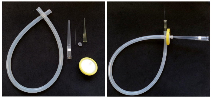 Figure 1. Assembling a mouth pipette. Left: Parts required to assemble a mouth pipette with filter. Right: The assembled pipette. Please click here to view a larger version of this figure.
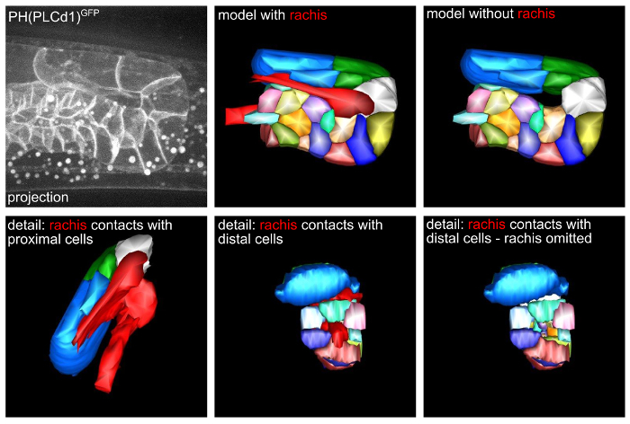 Figure 2. A 3D model of the gonad turn region. Top left: 3D projection of a single time point from time-lapse microscopy data. Top middle and right: 3D models of the microscopy data. Bottom: Details of cell-rachis contacts. Please click here to view a larger version of this figure.
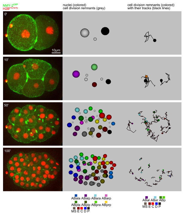 Figure 3. Tracking of nuclei and cell division remnants. Left: 3D projections from time-lapse microscopy data. Middle: Snapshots of the model obtained from tracking both nuclei (colored spheres) and cell division remnants (grey spheres). Right: Snapshots from cell division remnant tracking. The paths for the remnants are also shown. Please click here to view a larger version of this figure.
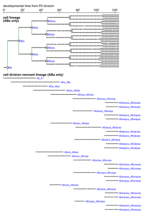 Figure 4. Cell and cell division remnant lineages for the ABa sublineage. Lineages from a representative embryo are shown. Cell divisions are marked by squares. Each tick mark corresponds to 1 min. The cell division remnants were named after the daughters that arise from the division during which the remnant is generated. Please click here to view a larger version of this figure.
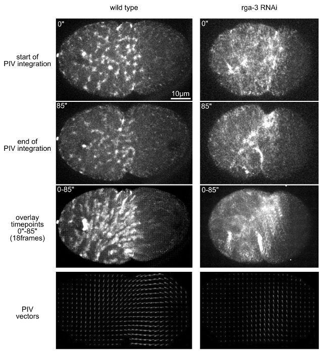 Figure 5. Analysis of cortical contractile flow with PIV. Top: 3D projection stills from time-lapse microscopy that depict the start (first row) and end (second row) of the time window used to calculate the vector field with PIVlab. The third row of panels shows the overlay of all time points of the time window. Bottom: Vector fields obtained by PIVlab. Please click here to view a larger version of this figure.
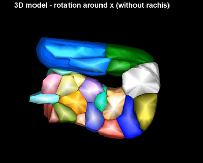
Video 1 - related to Figure 2. A 3D model of the gonad turn region. The video starts with scrolling through the entire stack of planes used to segment the cells. Afterwards a 3D maximum projection of the stack is shown, followed by the 3D segementation model rotating around the x and y axes (with and without the segmented gonad's rachis).

Video 2 - related to Figure 3. Tracking of nuclei and cell division remnants. Left: 3D projections from time-lapse microscopy data. Middle: The model obtained from tracking both nuclei (colored spheres) and cell division remnants (grey spheres). Right: Cell division remnants and their trajectories. Scale bar = 10 µm.

Video 3 - related to Figure 5. Analysis of cortical contractile flow with PIV. 3D maximum projection time-lapse recordings of a representative wild type and rga-3 RNAi embryo used to calculate the vector field with PIVlab. Scale bar = 10 µm.
Discussion
Through object tracking in development, in particular nuclear tracking, it has been possible to elucidate central patterning mechanisms of C. elegans embryogenesis1,23,24. Expanding this strategy to higher throughput, it has been recently possible to uncover additional patterning rules and to propose a method how to deduce patterning rules de novo10. For many mutants, however, the precise patterning defects are still unknown. The methods described here are tools that can be instrumental in their elucidation. Importantly, it has become clear in recent years that although many other model systems do not follow an invariant development like C. elegans, object tracking and analysis of the quantitative tracking data is a crucial tool to identify developmental mechanisms and mechanisms of disease.
The methods shown here are especially well suited in the situation where it would either be too challenging to implement more complex and/or self-generated software solutions, or simply too costly to implement commercial software tools, respectively. Importantly, the tools discussed here enable the researcher to load and analyze any data independently on which instrument they have been recorded. Moreover, if proprietary image acquisition software is used, ImageJ provides the Bio-Formats plugin that can load data in proprietary formats and save them in standard formats (jpeg, tiff).
A critical step in all protocols that rely on time lapse microscopy is to choose the conditions right to obtain sufficient contrast in microscopy images, and, at the same time, to reduce radiation exposure to the specimen. This heavily depends on the type of microscope used and it is generally recommended to use fast scanning techniques such as spinning disc or single plane illumination microscopy. Specifically, for PIV of cortical dynamics, older versions of point-scanning microscopes might be too slow to allow capturing cortical signals at a sufficient resolution and speed to perform valid analyses. It is therefore always crucial to carefully evaluate the radiation exposure and test the viability of the specimen. In addition, although the protocols discussed here use micobeads to mount embryos, it is also possible to use agarose pads, which just takes a little more time to prepare but is less expensive and with some experience equally reproducible. However, it should be pointed out that the combination of agarose pad and nanobeads is the superior method for long-term immobilization of adult worms since it avoids the use of any paralyzing agent, e.g., levamisole.
It should be pointed out that the tools discussed here have their limitations since they do not perform fully automated data analysis. However, for structures like cell division remnants, it is often challenging to identify a molecular marker that only stains this structure, which is crucial for reliable tracking. A major future challenge therefore lies in including features like machine learning and adaptable detection/segmentation algorithms in the easy-to-use and open access software that we discuss here. Some of these features can be found in other software modules, in particular software that can deal with repeated tracking over longer time intervals, or that can compare large sets of tracking data (e.g., StarryNite/AceTree25 or Nucleitracker4D26, which are designed to track nuclei using histone-fusion proteins or spindles27, or Simi BioCell28). These tools may be more complex to implement when aiming at tracking of structures other than nuclei. Notwithstanding the particular structure that should be tracked, these programs are generally very helpful when large amounts of image data will be analyzed. Importantly, there is compatibility between the above mentioned software modules.
When working with other model systems (e.g., fly embryos, mammalian cultured cells, etc.), the methods presented here are also well suited to track orthologous structures as described above. More importantly, independently of the model system under investigation, different subcellular structures, e.g., centrosomes, nucleoli, microparticles, vesicles, etc. can be readily tracked, only the acquisition parameters have to be adjusted to ensure complete capturing of object tracks.
Disclosures
Research in the lab of CP is funded by the Deutsche Forschungsgemeinschaft (EXC 115; FOR 1756) and the LOEWE Research Cluster Ubiquitin Networks. CP is further supported by the European Union Framework Program 7 (Marie Curie Actions Project 326632).
Acknowledgments
The authors have nothing to disclose.
References
- Sulston JE, Schierenberg E, White JG, Thomson JN. The embryonic cell lineage of the nematode Caenorhabditis elegans. Dev. Biol. 1983;100(1):64–119. doi: 10.1016/0012-1606(83)90201-4. [DOI] [PubMed] [Google Scholar]
- Kimmel CB, Warga RM. Tissue-specific cell lineages originate in the gastrula of the zebrafish. Science. 1986;231(4736):365–368. doi: 10.1126/science.231.4736.365. [DOI] [PubMed] [Google Scholar]
- Nishida H. Cell lineage analysis in ascidian embryos by intracellular injection of a tracer enzyme. III. Up to the tissue restricted stage. Dev. Biol. 1987;121(2):526–541. doi: 10.1016/0012-1606(87)90188-6. [DOI] [PubMed] [Google Scholar]
- Lee T, Luo L. Mosaic analysis with a repressible cell marker for studies of gene function in neuronal morphogenesis. Neuron. 1999;22(3):451–461. doi: 10.1016/s0896-6273(00)80701-1. [DOI] [PubMed] [Google Scholar]
- Livet J, Weissman TA, Kang H, Draft RW, Lu J, Bennis RA, Sanes JR, Lichtman JW. Transgenic strategies for combinatorial expression of fluorescent proteins in the nervous system. Nature. 2007;450(7166):56–62. doi: 10.1038/nature06293. [DOI] [PubMed] [Google Scholar]
- Fernandez R, Das P, Mirabet V, Moscardi E, Traas J, Verdeil JL, Malandain G, Godin C. Imaging plant growth in 4D: robust tissue reconstruction and lineaging at cell resolution. Nat. Methods. 2010;7(7):547–553. doi: 10.1038/nmeth.1472. [DOI] [PubMed] [Google Scholar]
- Olivier N, et al. Cell lineage reconstruction of early zebrafish embryos using label-free nonlinear microscopy. Science. 2010;329(5994):967–971. doi: 10.1126/science.1189428. [DOI] [PubMed] [Google Scholar]
- Kitajima TS, Ohsugi M, Ellenberg J. Complete kinetochore tracking reveals error-prone homologous chromosome biorientation in mammalian oocytes. Cell. 2011;146(4):568–581. doi: 10.1016/j.cell.2011.07.031. [DOI] [PubMed] [Google Scholar]
- Schrödel T, Prevedel R, Aumayr K, Zimmer M, Vaziri A. Brain-wide 3D imaging of neuronal activity in Caenorhabditis elegans with sculpted light. Nat. Methods. 2013;10(10):1013–1020. doi: 10.1038/nmeth.2637. [DOI] [PubMed] [Google Scholar]
- Du Z, Santella A, He F, Tiongson M, Bao Z. De novo inference of systems-level mechanistic models of development from live-imaging-based phenotype analysis. Cell. 2014;156(1-2):359–372. doi: 10.1016/j.cell.2013.11.046. [DOI] [PMC free article] [PubMed] [Google Scholar]
- Amat F, et al. Fast, accurate reconstruction of cell lineages from large-scale fluorescence microscopy data. Nat. Methods. 2014;11(9):951–958. doi: 10.1038/nmeth.3036. [DOI] [PubMed] [Google Scholar]
- He B, Doubrovinski K, Polyakov O, Wieschaus E. Apical constriction drives tissue-scale hydrodynamic flow to mediate cell elongation. Nature. 2014;508(7496):392–396. doi: 10.1038/nature13070. [DOI] [PMC free article] [PubMed] [Google Scholar]
- Singh D, Pohl C. Coupling of rotational cortical flow, asymmetric midbody positioning, and spindle rotation mediates dorsoventral axis formation in C. elegans. Dev. Cell. 2014;28(3):253–267. doi: 10.1016/j.devcel.2014.01.002. [DOI] [PubMed] [Google Scholar]
- Singh D, Pohl C. A function for the midbody remnant in embryonic patterning. Commun. Integr. Biol. 2014;7:e28533. doi: 10.4161/cib.28533. [DOI] [PMC free article] [PubMed] [Google Scholar]
- Kremer JR, Mastronarde DN, McIntosh JR. Computer visualization of three-dimensional image data using IMOD. J. Struct. Biol. 1996;116(1):71–76. doi: 10.1006/jsbi.1996.0013. [DOI] [PubMed] [Google Scholar]
- Henriksson J, Hench J, Tong YG, Johansson A, Johansson D, Bürglin TR. Endrov: an integrated platform for image analysis. Nat. Methods. 2013;10(6):454–456. doi: 10.1038/nmeth.2478. [DOI] [PubMed] [Google Scholar]
- Thielicke W, Stamhuis EJ. PIVlab - Towards User-friendly, Affordable and Accurate Digital Particle Image Velocimetry in MATLAB. Journal of Open Research Software. 2014;2(1):e30. [Google Scholar]
- Kim E, Sun L, Gabel CV, Fang-Yen C. Long-term imaging of Caenorhabditis elegans using nanoparticle-mediated immobilization. PLoS One. 2013;8(1):e53419. doi: 10.1371/journal.pone.0053419. [DOI] [PMC free article] [PubMed] [Google Scholar]
- Dickinson DJ, Ward JD, Reiner DJ, Goldstein B. Engineering the Caenorhabditis elegans genome using Cas9-triggered homologous recombination. Nat. Methods. 2013;10(10):1028–1034. doi: 10.1038/nmeth.2641. [DOI] [PMC free article] [PubMed] [Google Scholar]
- Schonegg S, Constantinescu AT, Hoege C, Hyman AA. The Rho GTPase-activating proteins RGA-3 and RGA-4 are required to set the initial size of PAR domains in Caenorhabditis elegans one-cell embryos. Proc. Natl. Acad. Sci. U. S. A. 2007;104(38):14976–14981. doi: 10.1073/pnas.0706941104. [DOI] [PMC free article] [PubMed] [Google Scholar]
- Schmutz C, Stevens J, Spang A. Functions of the novel RhoGAP proteins RGA-3 and RGA-4 in the germ line and in the early embryo of C. elegans. Development. 2007;134(19):3495–3505. doi: 10.1242/dev.000802. [DOI] [PubMed] [Google Scholar]
- Naganathan SR, Fürthauer S, Nishikawa M, Jülicher F, Grill SW. Active torque generation by the actomyosin cell cortex drives left-right symmetry breaking. Elife. 2014;3:e04165. doi: 10.7554/eLife.04165. [DOI] [PMC free article] [PubMed] [Google Scholar]
- Kaletta T, Schnabel H, Schnabel R. Binary specification of the embryonic lineage in Caenorhabditis elegans. Nature. 1997;390(6657):294–298. doi: 10.1038/36869. [DOI] [PubMed] [Google Scholar]
- Schnabel R, et al. Global cell sorting in the C. elegans embryo defines a new mechanism for pattern formation. Dev. Biol. 2006;294(2):418–431. doi: 10.1016/j.ydbio.2006.03.004. [DOI] [PubMed] [Google Scholar]
- Murray JI, Bao Z, Boyle TJ, Waterston RH. The lineaging of fluorescently-labeled Caenorhabditis elegans embryos with StarryNite and AceTree. Nat. Protoc. 2006;1(3):1468–1476. doi: 10.1038/nprot.2006.222. [DOI] [PubMed] [Google Scholar]
- Giurumescu CA, et al. Quantitative semi-automated analysis of morphogenesis with single-cell resolution in complex embryos. Development. 2012;139(22):4271–4279. doi: 10.1242/dev.086256. [DOI] [PMC free article] [PubMed] [Google Scholar]
- Dejima K, Kang S, Mitani S, Cosman PC, Chisholm AD. Syndecan defines precise spindle orientation by modulating Wnt signaling in C. elegans. Development. 2014;141(22):4354–4365. doi: 10.1242/dev.113266. [DOI] [PMC free article] [PubMed] [Google Scholar]
- Schnabel R, Hutter H, Moerman D, Schnabel H. Assessing normal embryogenesis in Caenorhabditis elegans using a 4D microscope: variability of development and regional specification. Dev Biol. 1997;184(2):234–265. doi: 10.1006/dbio.1997.8509. [DOI] [PubMed] [Google Scholar]


