

Abstract
Cone-beam computed tomography (CBCT) has been accepted as a useful tool for diagnosis and treatment planning in dentistry. Despite a growing trend of CBCT in dentistry, it has some disadvantages like artifacts. Artifacts are discrepancies between the reconstructed visual image and the actual content of the subject which degrade the quality of CBCT images, making them diagnostically unusable. Additionally, structures that do not exist in the subject may appear within images. Such structures can occur because of patient motion, the image capture and reconstruction process. To optimize image quality, it is necessary to understand the types of artifacts. This article aims to throw light on the various types of artifacts associated with CBCT images.
Keywords: Aliasing artifacts, beam hardening, motion artifacts, scanner-related artifacts, stair step artifacts, zebra artifacts
INTRODUCTION
The first cone-beam computed tomography (CBCT) machine developed strictly for maxillofacial imaging was the NewTom-9000 (Quantitative Radiology, Verona, Italy). Since its development in 1998, there has been a rapid progression in the production of CBCT units manufactured for imaging the maxillofacial region. Like conventional CT used in medicine, CBCT provides a means for three-dimensional (3D) imaging. However, in dentistry, CBCT is designed for imaging the maxillofacial region and, therefore, can be applied to diagnostic imaging tasks specific to the field of dentistry. In addition, the radiation dose is lower in CBCT used in dentistry than in CT used in medicine.[1]
However, there are some drawbacks in using CBCT as an imaging technique. The presence of gray-level non-uniformities in CBCT contributes to artifact formation in reconstructed CBCT images. In CT, the term “artifact” refers to any systematic discrepancy between the CT numbers in the reconstructed image and the true attenuation coefficients of the object.[1] Artifacts are commonly encountered in clinical CT, and may obscure or simulate pathology. There are many different types of CT artifacts [Figure 1], including noise, beam hardening, scatter, pseudoenhancement, motion, cone beam, helical, ring, and metal artifacts.[2]
Figure 1.
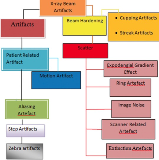
Classification of artifacts
X-RAY BEAM ARTIFACTS
Beam hardening
Beam hardening is one of the most prominent sources of artifacts. An X-ray beam is composed of individual photons with a range of energies. As the beam passes through an object, it becomes “harder,” i.e., its mean energy increases, because the lower-energy photons are absorbed more rapidly than the higher-energy photons.[3,4] Highly absorbing materials such as metal[3,5,6] function as a filter positioned within the object. If the emitted spectrum contains more relatively lower-energetic rays than that recorded on the detector (i.e. the beam is hardened), a non-linear error (relatively too much energy recorded in the beam path behind highly absorbing materials) is induced in the recorded data. In the 3D reconstruction, the error is back projected into the volume, resulting in darks streaks.[3,5,7] Because the CBCT X-ray beam is heterochromatic and has lower mean kilovolt (peak) energy compared with conventional CT, this artifact is more pronounced on CBCT images. These can be reduced using iterative reconstruction. Two types of artifact can result from this effect: The so-called cupping artifacts and the appearance of dark bands or streaks between dense objects in the image [Figure 2].[1,2,6,8] In clinical practice, it is advisable to reduce the field of view (FOV)[9] to avoid scanning regions susceptible to beam hardening (e.g., metallic restorations, dental implants), which can be achieved by collimation, modification of patient positioning, or separation of the dental arches.[6,5] More recently, dental CBCT manufacturers have introduced artifact reduction technique algorithms within the reconstruction process (e.g., Scanora 3D; SOREDEX, Helsinki, Finland). These algorithms reduce image noise, metal and motion-related artifacts and require fewer projection images, and therefore may allow for a lower acquisition dose. However, they are computationally demanding and require increased reconstruction times.[10,11,12,13,14]
Figure 2.
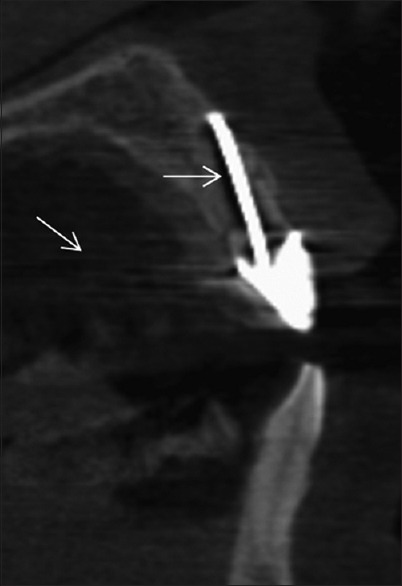
Beam hardening artifact adjacent to a silver point and metal artifact streaks from the metal coping
Manufacturers minimize beam hardening by using filtration, calibration correction, and beam hardening correction software.[15]
Filtration
A flat piece of attenuating, usually metallic material is used to “pre-harden” the beam by filtering out the lower-energy components before it passes through the patient. An additional “bowtie” filter further hardens the edges of the beam, which will pass through the thinner parts of the patient.[15]
Calibration correction
Manufacturers calibrate their scanners using phantoms in a range of sizes. This allows the detectors to be calibrated with compensation tailored for the beam hardening effects of different parts of the patient.[15]
Beam hardening correction software
An iterative correction algorithm may be applied when images of bony regions are being reconstructed. This helps minimize blurring of the bone–soft tissue interface in brain scans and also reduces the appearance of dark bands in non-homogeneous cross sections.[15]
Avoidance of beam hardening by the operator
It is sometimes possible to avoid scanning bony regions, either by means of patient positioning or by tilting the gantry.[15]
Cupping artifact
The cupping effect artifact is demonstrated when a uniform cylindrical object is imaged. X-rays passing through the middle portion of a uniform cylindrical phantom are hardened more than those passing though the edges because they are passing though more material. As the beam becomes harder, the rate at which it is attenuated decreases. The gray levels decrease in value in the center of the aluminum cylinder owing to the increase in transmitted intensity to the detector from the presence of beam hardening and scatter radiation occurring during image acquisition. Therefore, the resultant attenuation profile differs from the ideal profile that would be obtained without beam hardening and displays a characteristic cupped shape artifact.[1,15]
PATIENT-RELATED ARTIFACTS
Patient motion can cause misregistration of data, which appears as unsharpness [Figure 3] in the reconstructed image. This unsharpness can be minimized by using a head restraint and as short a scan time as possible.[2,12]
Figure 3.
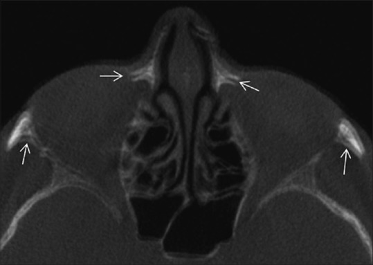
Blurring and double cortices caused by motion artifact
Avoidance of metal artifacts by the operator
Patients are normally asked to take off removable metal objects such as jewelry before scanning commences. For non-removable items, such as dental fillings, prosthetic devices, and surgical clips, it is sometimes possible to use gantry angulation to exclude the metal inserts from scans of nearby anatomy. When it is impossible to scan the required anatomy without including metal objects, increasing technique, especially kilovoltage, may help penetrate some objects, and using thin sections will reduce the contribution due to partial volume artifact.[15]
Motion artifacts–misalignment artifacts
These two sources of error are closely related in that a misalignment of any of the three components (source, object, and detector) causes inconsistencies in the back projection process. Patient motion can cause misregistration artifacts within the image. If an object moves during the scanning process, the reconstruction does not account for that move since no information on the movement is integrated in the reconstruction process.[2,12,14]
Hence, the lines along which the back projection takes place do not correspond to the lines along which the attenuation had been recorded, simply because the object has moved during the acquisition. The smaller the voxel size (i.e., the higher the spatial resolution), the smaller the movement necessary to move the patient structures out of the “correct” voxels. Movement artifacts present as double contours.[2,11,12,16,17]
Misalignment of the source relative to the detector or the unit of the two of them relative to the stationary patient causes the same sort of inconsistencies as described above. This applies also for minute deviations, e.g., deviations from a truly planar circular source and detector trajectory. This results in poor overall image quality. Since the resolutions of the present CBCT are very high, ranging from 0.08 to 0.4 mm, even small motions can have a detrimental effect on image quality. To prevent these sorts of errors poses great challenges on the mechanical stability of the systems.[2,12,16,17]
Avoidance of motion artifacts by the operator
The use of positioning aids is sufficient to prevent voluntary movement in most patients. However, in some cases (e.g., pediatric patients), it may be necessary to immobilize the patient by means of sedation. Using as short a scan time as possible helps minimize artifacts when scanning regions prone to movement. Respiratory motion can be minimized if patients are able to hold their breath for the duration of the scan. The sensitivity of the image to motion artifacts depends on the orientation of the motion. Therefore, it is preferable if the start and end position of the tube is aligned with the primary direction of motion, e.g., vertically above or below a patient undergoing a chest scan. Specifying body scan mode, as opposed to head scan mode, may automatically incorporate some motion artifact reduction in the reconstruction.[15,18,19,20,21]
SCANNER-RELATED ARTIFACTS
Ring artifacts
Visible as concentric rings [Figure 4] centered around the location of the axis of rotation that result from imperfections in scanner detection or poor calibration. They are most prominent when homogeneous media are imaged. Owing to the circular trajectory and the discrete sampling process, these inconsistencies appear as rings in the planes coplanar with the movement plane of the source (axial planes in CBCT).[2,10,11,12,20,22]
Figure 4.
Ring artifact caused by calibration error
Avoidance and software corrections
The presence of circular artifacts in an image is an indication that the detector gain needs recalibration or may need repair services. Selecting the correct scan field of view may reduce the artifact[6] by using calibration data that fit more closely to the patient anatomy. All modern scanners use solid-state detectors, but their potential for ring artifacts is reduced by software that characterizes and corrects detector variations.[15]
IMAGE NOISE
Noise is defined as an unwanted, randomly and/or non-randomly distributed disturbance of a signal that tends to obscure the signal's information content from the observer. Noise affects images produced by cone-beam CT units by reducing low contrast resolution [Figure 5],[23] making it difficult to differentiate low-density tissues, thereby reducing the ability to segment effectively. Some authors also include “detector blurring” in terms of noise. CBCT machines for dose reduction reasons are operated at milliamperes that are approximately one order of magnitude below those of medical CT machines. Thus, the signal-to-noise ratio is much lower than in CT. In other words, a high noise level is to be expected in CBCT images. Noise represents itself in inconsistent attenuation (gray) values in the projection images, i.e., large standard deviations in areas where a constant attenuation should be present. When back projecting these incorrect values, the computed attenuation coefficient “m” in the volume will also be erroneous. This is because of the use of an area detector, non-linear attenuation is recorded and contributes to image degradation or noise. The scatter-to-primary ratios are about 0.01 for single-ray CT and 0.05–0.15 for fan-beam and spiral CT, and may be as large as 0.4–2.0 in CBCT.[2,10,11,12]
Figure 5.
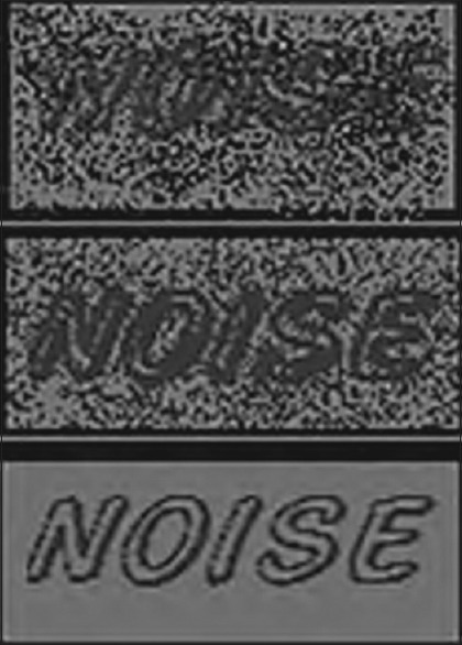
Noise
Scatter
Scatter, on the other hand, is caused by those photons that are diffracted from their original path after interaction with matter. This additional share of scattered X-rays results in increased measured intensities, since the scattered intensities simply add to the primary intensity (I0). It is easy to see that back projection of overestimated intensities yields overestimated intensities in every voxel along the path; this corresponds to an underestimation of absorption. This effect has long been known for classical CT. The reconstructed error is dependent on the object and is proportional to the amount of scatter present. The larger the detector, the higher the probability that scattered photons incite it. Thus, the image degrading effect of scattered radiation will affect CBCT machines more than classical highly collimated fan-beam CTs. Scatter causes streak artifacts[24] in the reconstruction that are very similar to those caused by beam hardening. Scatter is well known to further reduce soft-tissue contrast and it will also affect the density values of all other tissues.[2,10,11,12,15,25]
Extinction artifacts
These are often termed “missing value artifacts.” If the object under study contains highly absorbing material, e.g., prosthetic gold restorations, then the signal IP recorded in the detector pixels behind that material may be close to zero or actually zero. A typical gold crown may be estimated to have at least 2–3 mm of thickness (when considering that the X-rays have to pass through both sides of it). This results in absorption of the mean energy of 90–97%. Clearly, two gold restorations or even one with thicker walls will result in zero incident intensity on the detector. Consequently, no absorption can be computed and severe artifacts are induced as these zero entries are back projected into the volume.[2,10,11,12] Postprocessing image filters can help to correct raw data in areas of low photon count, identify portions of the raw projection data where there is a disproportionate loss in X-ray signal, and apply a local 3D filter with smoothing effect to reduce image noise and streak artifacts.[13,15]
Exponential edge gradient effect
This effect appears at sharp edges with high contrast to neighboring structures. It is caused by averaging the measured intensity over a finite beam width (and finite focal spot width), while the mathematics used for the reconstruction assumes zero width. The width is determined by the focal spot and detector pixel size in combination with the imaging geometry of the machine. The exponential edge gradient effect (EEGE) error induced in the projection values has been proven to be negative always, i.e. it will always reduce the computed density value. The EEGE is known to cause streaks tangent to long straight edges in the projection direction. As sharp edges metallic FPD with of high contrast may commonly occur in the oral cavity, e.g., at metallic crown borders.[2,10,11,12,15]
Aliasing artifacts
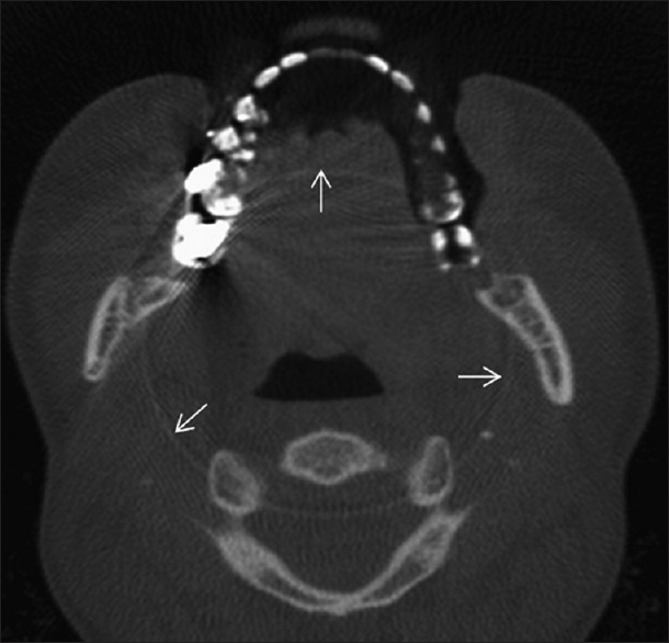
Aliasing in CBCT lies in the divergence of the cone beam. In each projection, the voxels close to the source will be traversed by more recorded “rays” [Figure 6] than those close to the detector. This causes aliasing which represents itself as line patterns (moire patterns), commonly diverging toward the periphery of the reconstructed volume. Aliasing may also be introduced by a crude interpolation between the back projection “lines” and the voxel they traverse. Ideally, the exact volume a voxel shares with the “line-fragment” crossing through it should be used to compute the intensity of the voxel. Owing to computational limitations, however, often only crude but fast approximations (i.e., the length of the fragment) enter the computation. This causes aliasing artifacts which can be avoided by a better interpolation scheme that is more closely conforming with the actual physical measurement conditions.[2,10,11,12]
Figure 6.
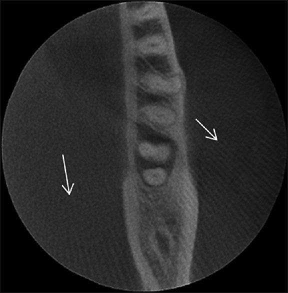
Aliasing pattern artifact
Stair step artifacts
Stair step artifacts appear around the edges of structures in multiplanar and 3D reformatted images when wide collimations and non-overlapping reconstruction intervals are used. They are less severe with helical scanning, which permits reconstruction of overlapping sections without the extra dose to the patient that would occur if overlapping axial scans were obtained. Stair step artifacts are virtually eliminated in multiplanar and 3D reformatted images from thin section data obtained with today's multisection scanners.[1,15]
Zebra artifacts
Faint stripes may be apparent in multiplanar and 3D reformatted images from helical data because the helical interpolation process gives rise to a degree of noise inhomogeneity along the z axis. This “zebra” effect becomes more pronounced away from the axis of rotation because the noise inhomogeneity is worse off axis.[15]
Summary
Artifacts are common in today's CBCT. Since artifacts may interfere with the diagnostic process performed on CBCT data sets, every user should be aware of their presence. Consequently, more modern approaches attempt to avoid reconstruction errors by supplementing either missing information or incorrect information in the projection images. But all these require massive computational power, which has so far prevented them from being used in commercial scanners in daily routine work. The ever-increasing computational speed, however, and particularly the advancement in graphics processing units, has already drastically reduced the computational time required. As this process will continue, it is very likely that enhanced reconstruction methods will be much more common in the near future. They will help to reduce various sorts of artifacts.
Financial support and sponsorship
Nil.
Conflicts of interest
There are no conflicts of interest.
REFERENCES
- 1.Hunter AK, McDavid WD. Characterization and correction of cupping effect artefacts in cone beam CT. Dentomaxillofac Radiol. 2012;41:217–23. doi: 10.1259/dmfr/19015946. [DOI] [PMC free article] [PubMed] [Google Scholar]
- 2.Schulze R, Heil U, Groβ D, Bruellmann DD, Dranischnikow E, Schwanecke U, et al. Artefacts in CBCT: A review. Dentomaxillofac Radiol. 2011;40:265–73. doi: 10.1259/dmfr/30642039. [DOI] [PMC free article] [PubMed] [Google Scholar]
- 3.Esmaeili F, Johari M, Haddadi P, Vatankhah M. Beam hardening artifacts: Comparison between two cone beam computed tomography scanners. J Dent Res Dent Clin Dent Prospects. 2012;6:49–53. doi: 10.5681/joddd.2012.011. [DOI] [PMC free article] [PubMed] [Google Scholar]
- 4.Ibraheem I. Reduction of artifacts in dental cone beam CT images to improve the three dimensional image reconstruction. J Biomed Sci Eng. 2012;5:409–15. [Google Scholar]
- 5.Esmaeili F, Johari M, Haddadi P. Beam hardening artifacts by dental implants: Comparison of cone-beam and 64-slice computed tomography scanners. Dent Res J (Isfahan) 2013;10:376–81. [PMC free article] [PubMed] [Google Scholar]
- 6.Nabha W, Hong YM, Cho JH, Hwang HS. Assessment of metal artifacts in three-dimensional dental surface models derived by cone-beam computed tomography. Korean J Orthod. 2014;44:229–35. doi: 10.4041/kjod.2014.44.5.229. [DOI] [PMC free article] [PubMed] [Google Scholar]
- 7.Jin SO, Kim JG, Lee SY, Kwon OK. Bone-induced streak artifact suppression in sparse-view CT image reconstruction. Biomed Eng Online. 2012;11:44. doi: 10.1186/1475-925X-11-44. [DOI] [PMC free article] [PubMed] [Google Scholar]
- 8.Parirokh M, Ardjomand K, Manochehrifar H. Artifacts in cone-beam computed tomography of a post and core restoration: A case report. Iran Endod J. 2012;7:98–101. [PMC free article] [PubMed] [Google Scholar]
- 9.Bechara B, McMahan CA, Geha H, Noujeim M. Evaluation of a cone beam CT artefact reduction algorithm. Dentomaxillofac Radiol. 2012;41:422–8. doi: 10.1259/dmfr/43691321. [DOI] [PMC free article] [PubMed] [Google Scholar]
- 10.Scarfe WC, Farman AG. What is cone-beam CT and how does it work? Dent Clin North Am. 2008;52:707–30, v. doi: 10.1016/j.cden.2008.05.005. [DOI] [PubMed] [Google Scholar]
- 11.Bhoosreddy AR, Sakhavalkar UP. Image deteriorating factors in cone beam computed tomography, their classification, measure to reduce them: A pictorial essay. J Indian Acad Oral Med Radiol. 2014;26:293–7. [Google Scholar]
- 12.Makins RS. Artifacts interfering with interpretation of cone beam computed tomography images. Dent Clin North Am. 2014;58:485–95. doi: 10.1016/j.cden.2014.04.007. [DOI] [PubMed] [Google Scholar]
- 13.Kataoka ML, Hochman MG, Rodriguez EK, Lin PJ, Kubo S, Raptopolous VD. A review of factors that affect artifact from metallic hardware on multi-row detector computed tomography. Curr Probl Diagn Radiol. 2010;39:125–36. doi: 10.1067/j.cpradiol.2009.05.002. [DOI] [PubMed] [Google Scholar]
- 14.Leng S, Zambelli J, Tolakanahalli R, Nett B, Munro P, Star-Lack J, et al. Streaking artifacts reduction in four-dimensional cone-beam computed tomography. Med Phys. 2008;35:4649–59. doi: 10.1118/1.2977736. [DOI] [PMC free article] [PubMed] [Google Scholar]
- 15.Barrett JF, Keat N. Artifacts in CT: Recognition and avoidance. Radiographics. 2004;24:1679–91. doi: 10.1148/rg.246045065. [DOI] [PubMed] [Google Scholar]
- 16.Zheng D, Ford JC, Lu J, Lazos D, Hugo GD, Pokhrel D, et al. Bow-tie wobble artifact: Effect of source assembly motion on cone-beam CT. Med Phys. 2011;38:2508–14. doi: 10.1118/1.3582944. [DOI] [PMC free article] [PubMed] [Google Scholar]
- 17.Spin-Neto R, Mudrak J, Matzen LH, Christensen J, Gotfredsen E, Wenzel A. Cone beam CT image artefacts related to head motion simulated by a robot skull: Visual characteristics and impact on image quality. Dentomaxillofac Radiol. 2013;42:32310645. doi: 10.1259/dmfr/32310645. [DOI] [PMC free article] [PubMed] [Google Scholar]
- 18.Zhang Q, Hu CY, Liu F, Goodman K, Rosenzweig EK, Mageras GS. Correction of motion artefacts in cone-beam CT using a patient-specific respiratory motion model. Med Phys. 2010;37:2901–9. doi: 10.1118/1.3397460. [DOI] [PMC free article] [PubMed] [Google Scholar]
- 19.Sureshbabu W, Mawlawi O. PET/CT imaging artifact. J Nucl Med Technol. 2005;33:156. quiz 163-4. [PubMed] [Google Scholar]
- 20.LU W, Parikh PJ, Hubenschmidt JP, Politte DG, Whiting BR, Bradley JD, et al. Reduction of motion blurring artifacts using respiratory gated CT in sinogram space: A quantitative evaluation. Med Phys. 2005;32:3295–304. doi: 10.1118/1.2074187. [DOI] [PubMed] [Google Scholar]
- 21.Marchant TE, Price GJ, Matuszewski BJ, Moore CJ. Reduction of motion artefacts in on-board cone beam CT by warping of projection images. Br J Radiol. 2011;84:251–64. doi: 10.1259/bjr/90983944. [DOI] [PMC free article] [PubMed] [Google Scholar]
- 22.Kincade K. Cone-beam CT artifacts: What's a dentist to do? Dentomaxillofac Radiol. 2011;40:265–73. [Google Scholar]
- 23.Bechara B, McMahan CA, Moore WS, Noujeim M, Geha H, Teixeira FB. Contrast-to-noise ratio difference in small field of view cone beam computed tomography machines. J Oral Sci. 2012;54:227–32. doi: 10.2334/josnusd.54.227. [DOI] [PubMed] [Google Scholar]
- 24.Miracle AC, Mukherji SK. Conebeam CT of the head and neck, Part 1: Physical principles. AJNR Am J Neuroradiol. 2009;30:1088–95. doi: 10.3174/ajnr.A1653. [DOI] [PMC free article] [PubMed] [Google Scholar]
- 25.Zhao W, Zhu J, Wang L. Fast scatter artifacts correction for Cone-Beam CT without system modification and repeat scan. Med Phys. 2015 doi: 10.1118/1.4943796. [DOI] [PMC free article] [PubMed] [Google Scholar]