Abstract
Droplet interface bilayer (DIB) networks are emerging as a cornerstone technology for the bottom up construction of cell-like and tissue-like structures and bio-devices. They are an exciting and versatile model-membrane platform, seeing increasing use in the disciplines of synthetic biology, chemical biology, and membrane biophysics. DIBs are formed when lipid-coated water-in-oil droplets are brought together—oil is excluded from the interface, resulting in a bilayer. Perhaps the greatest feature of the DIB platform is the ability to generate bilayer networks by connecting multiple droplets together, which can in turn be used in applications ranging from tissue mimics, multicellular models, and bio-devices. For such applications, the construction and release of DIB networks of defined size and composition on-demand is crucial. We have developed a droplet-based microfluidic method for the generation of different sized DIB networks (300–1500 pl droplets) on-chip. We do this by employing a droplet-on-rails strategy where droplets are guided down designated paths of a chip with the aid of microfabricated grooves or “rails,” and droplets of set sizes are selectively directed to specific rails using auxiliary flows. In this way we can uniquely produce parallel bilayer networks of defined sizes. By trapping several droplets in a rail, extended DIB networks containing up to 20 sequential bilayers could be constructed. The trapped DIB arrays can be composed of different lipid types and can be released on-demand and regenerated within seconds. We show that chemical signals can be propagated across the bio-network by transplanting enzymatic reaction cascades for inter-droplet communication.
I. INTRODUCTION
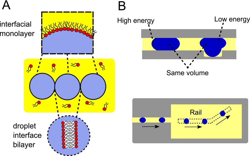
The past decade has seen the emergence of droplet interface bilayers (DIBs) as a powerful and versatile model membrane system. The principle behind the construction of DIBs is a simple one: water droplets, when placed in an oil solution containing amphiphilic lipids, will have a lipid monolayer self-assemble around them. When two or more droplets are brought into contact, oil is excluded from the interface and a bilayer is formed between them (Fig. 1(a)).1,2
FIG. 1.
(a) Bilayers are formed at the interfaces of lipid coated water-in-oil droplets. By bringing together more than two droplets, networks of sequential bilayers can be generated. (b) When a squeezed droplet partially enters a “rail” (a groove on the channel surface) its surface energy is reduced. This creates an energy gradient at the edge of the rail, which leads to an attractive force pulling it towards the deeper areas. This lower energy state causes the droplet to continue travelling along the direction of the rail, meaning the direction of travel can be defined in 2D space.
There are multiple advantages of DIB systems over alternative model membranes such as liposomes, black lipid membranes, and supported lipid bilayers. DIBs can be stable for weeks,3 are capable of withstanding mechanical perturbations,4 can easily have electrodes inserted for electrical characterisation, and can be used to generate asymmetric bilayers.5 Uniquely, by joining up more than two droplets, DIB networks and arrays of a defined architecture can be constructed, which can be functionalised with biological machinery to yield biomimetic electrical devices,6–8 artificial cells,9–11 and tissue mimics.12 They have also been used for the study of ion channels,13 for the quantification of ion flux through membrane proteins,14 and for dynamic control of protein concentrations.15 Recent advances in microfluidic DIB generation have provided unique insight into the dynamic morphological behaviours of bilayer due to evaporation from the micron-scale droplets.16,17 There have also been developments concerning the generation of air-stable DIBs, which do not sit in a bulk oil solvent, further widening their potential applications.18
The most common approach for the construction of DIB networks is via manual pipetting and manipulation of aqueous droplets.1 This technique has inherent limitations due to the large size of the droplets produced, the low-throughput at which droplets are generated, and the poor control over droplet location and network architecture. In response to this, there have been several microfluidic technologies developed. Specifically, electrowetting methods have been employed,19 but these cannot be used to generate extended DIB networks. More recently, droplet generators have been used to construct networks, where pL droplets are packed in a chip of defined geometry leading to 2D and 3D networks of hundreds of bilayers.20,21 However, forming networks of different sizes requires redesigning the device, and forming several networks within the same device is not possible.
Villar et al. adopted a microfluidic approach whereby thousands of droplets were individually printed on a substrate to yield a material that resembled tissues in its elastic properties and ability to exhibit collective and co-operative behaviour, such as folding and transmittance of electrical signals down defined paths. However, this was done in a bulk oil environment, and not on-chip, and required a bespoke 3D droplet printer.12 Another recently reported study utilized 3D printed fabrication of a polydimethylsiloxane (PDMS) based chip for the generation of millifluidic DIBs.22 This method uses on demand droplet generation which requires a charge in the droplet which may be undesirable, and it can also only be used for extremely large (2 μl) droplets. Others have taken the advantage of PDMS permeability to oil to automate the generation of isolated DIBs in microfluidic channels.23 Finally, Czekalska et al. have used the high-throughput nature of droplet microfluidics to automate the production of single DIBs and have demonstrated in principle the potential for repetitive electrical interrogations of multiple bilayers, with applications for ion channel screening.24
The development of reproducible and stable methods to generate extensive networks of micron-scale DIBs on-chip still remains a challenge. In order to improve the functionalities and applications of DIB networks, control over individual droplet composition, size, and location must be achieved. In this paper, we use a DIB-on-rail microfluidic chip technology to address this. Droplets of different sizes are generated and are directed to different “rails” (grooves on the channel substrate, Fig. 1(b)), where they are trapped leading to multiple linear networks of DIBs, each containing droplets of a defined size. By transplanting an engineered enzymatic signalling cascade into the DIB network, we demonstrated inter-droplet chemical communication and signal propagation through the network.
II. RESULTS AND DISCUSSION
A. Microfluidic chip working principle
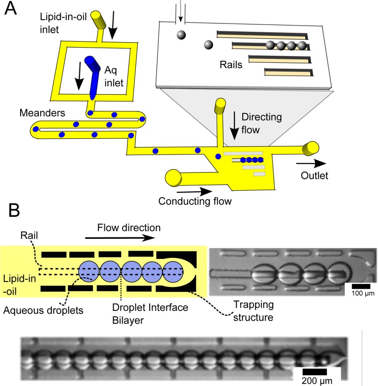
We designed a microfluidic chip capable of generating and trapping droplets of varying sizes, and guiding them down microfabricated rails, leading to multiple parallel DIB networks, each one containing droplets of defined size. The device operates in the following manner (Fig. 2). First, lipid-coated droplets of different sizes are generated in a flow focusing junction using gravity to drive pressure. The droplets then travel through a meandering channel, allowing time for them to be effectively coated by a lipid monolayer. These droplets are then fed into a wide central chamber containing several rails (deeper grooves on the channel substrate).
FIG. 2.
(a) Schematic of device. First, water in oil droplets are generated at a flow-focussing junction. Droplets travel along meanders, providing sufficient time for lipid-monolayers to self-assemble at the interface. Droplets then enter the sorting chamber, where they are directed to one of four rails by a directing flow. (b) Where the rails come to an end, droplets are trapped and accumulate next to each other, resulting in a droplet interface bilayer network. Networks of up to 20 bilayers could be formed in this way.
At all times, droplets are squeezed vertically by the channel (Fig. 1(b)). Where the droplets meet the rails, they become less squeezed as the flattened droplets partially enter the cavity of the track, which reduces their interfacial surface energy. This provides an energetic driving force for the droplet to travel along the rails, as droplets are captured by these areas of reduced confinement.25,26
The physical principle underlying this phenomenon is as follows. The surface energy (εγ) of a water/oil droplet with a defined surface tension (γ) is given by εγ = γ × droplet surface area. The droplet surface area, and thus the surface energy, is at a minimum when the droplet adopts a spherical shape. If the droplet is confined in the vertical direction, where it is squeezed and adopts a pancake shape, its surface energy is raised: the greater the confinement the greater the surface energy. When the droplet lies in a groove on a substrate (i.e., a rail), it has a reduced confinement—and therefore a lower energy—than when it is off the groove. Comprehensive discussions of the physical principles underlying trapping droplets on rails have been discussed elsewhere.27
There are several rails arranged parallel to one another in the main chamber. Which rail the droplet is directed to depends on the flow rates of an auxiliary directing oil stream perpendicular to the direction of travel of the droplets. By changing this flow rate droplets can be directed to enter different rails in the chamber. The droplets continue travelling down the rail until the rail comes to an end, and the droplets are prevented from moving using a micro-fabricated trapping structure. Droplets are then accumulated in a given row, one behind the other leading to a linear network of DIBs (Fig. 2(b)).
B. Parallel multi-sized DIB networks
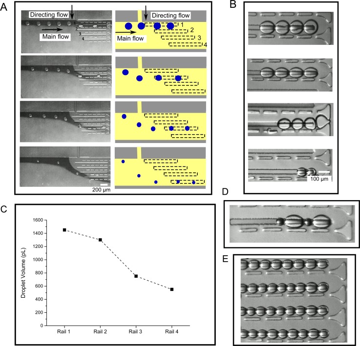
Throughout the experiments, the only flow rate which was varied was that of the directing flow. The flow rates of the flow-focussing junction were kept constant, leading to an initially monodisperse stream of droplets. This was subsequently directed to each one of the four rails by changing the flow rates of the directing flow. Changing the flow rate of the directing flow in turn led to different sized droplets being produced upstream as the pressures in the droplet generation regions changed. In this way, different sized droplets (from 300 to 1450 pl) were produced over time, which could be directed along different rails.
Using this method we generated 4 different linear DIB networks on rails, with each network containing droplets of different sizes (Fig. 3). Larger droplets were trapped in the tracks closer to the droplet inlet channels, and smaller droplets trapped further away. After droplets were guided down the rail, they were stopped on the rail by stopping the flow. Droplets then came into contact with one another, and DIBs formed between them were shown to be stable for monitoring over periods of up to 30 min. At any point, the droplets could be released by restoring the flow, and new DIB networks could be generated by reverting back to the original flow parameters.
FIG. 3.
(a) Droplets of varying sizes were guided into each of the four rails via a directing flow, with the larger droplets directed to Rail 1 at the top of the image, and smaller droplets to Rails 2, 3, and 4 at the bottom. Dye was added to the main flow to provide a contrast allowing the flow direction to be visualised. (b) Images of different sized DIB networks in the four rails. (c) Graph showing the average volume of droplets present in the four rails (N = 10). (d) Example of a DIB networks with variable droplet sizes on a single rail. (e) Image of a multi-array DIB network, with uniform droplet sizes.
In addition to forming parallel DIB networks of defined sizes, it was also possible to generate multiple DIB arrays of uniform size if a continuous stream of monodisperse droplets were produced (Fig. 3(e)), leading to DIB arrays of up to 20 droplets. Furthermore, in addition to showing the ability to direct droplets of the same size in the same rail, we also demonstrated the ability to trap droplets of different sizes within the same rail, using the same principle (Fig. 3(d)).
DIB networks were successfully formed using two types of lipid, 1,2-dioleoyl-sn-glycero-3-phosphocholine (DOPC) and 1,2-diphytanoyl-sn-glycero-3-phosphocholine (DPhPC). These lipids have unsaturated and saturated fatty acid tail regions which demonstrates the robustness of the device. Successful generation of parallel DIB networks of varying sizes was achieved across a range of generation rates, from 130 droplets/min to 60 droplets/min.
C. Mass transfer experiments
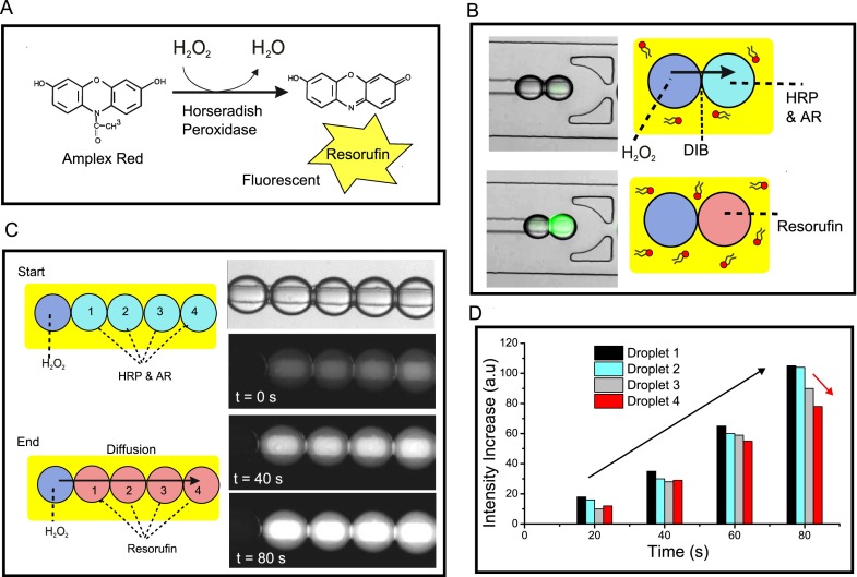
We validated the presence of bilayers and the ability to use the DIB networks for mass-transport studies by showing the propagation of a chemical signal across the network. To do this, we use the reaction between H2O2 (which can diffuse through bilayers) and Amplex Red in the presence of the enzyme horseradish peroxidase (HRP) to yield a fluorescent molecule, resorufin (Fig. 4(a)).28 We constructed a linear array where the first droplet contained H2O2 and all subsequent droplets contained HRP and Amplex Red (Fig. 4(b)). The production of a network with droplets of two different compositions was achieved as before, but using two droplet generation modules with different inlets. Flow-rates were adjusted so that for every 1 droplet containing H2O2, there were 4 droplets containing HRP/Amplex Red.
FIG. 4.
(a) Reaction scheme of enzymatic reaction between Amplex Red (AR) and H2O2, mediated by Horseradish Peroxidase (HRP), leading to the fluorescent product, resorufin. (b) Schematic of the DIB mass transfer experiment. One drop contained H2O2, the other AR. As soon as a DIB was formed, membrane permeable H2O2 transferred to the adjacent droplet, leading to the synthesis of a fluorescent product. (c) An extension of the assay to a five droplet network, where the enzymatic cascade reaction sequentially propagated through the droplets over time. (d) Graph showing fluorescence levels of the four dye-containing droplets over time. This shows that droplets increased in fluorescence as the reaction proceeded (black arrow) and that the droplets further away from the H2O2, source had smaller fluorescence levels (red arrow).
As soon as the DIB network was formed, a fluorescence signal was seen to propagate across the droplets, demonstrating that H2O2 diffused from one droplet to the next, initiating the reaction to produce resorufin. Image analysis revealed that (i) the intensity of all droplets increased over time as the reaction progressed and (ii) the closer droplets were to the H2O2 source, the brighter they were (Figs. 4(c) and 4(d)).
III. MATERIALS AND METHODS
A. Chemicals
Squalene oil (Sigma Aldrich) was used as the main oil carrier. Sudan red dye (Sigma Aldrich) was used to dye the oil and visualize the main carrier flow on chip. Patent Blue dye (Sigma Aldrich) was used to perform precise measurements of the produced droplet volume. All lipids were purchased from Avanti Polar Lipids as powders. The aqueous phase was composed of deionised water unless otherwise stated. The lipid-in-oil solution was prepared at 2 mg ml−1 by sonicating the lipid/oil mixture for 60 min at 50 °C. All reagents for the mass-transfer experiments were purchased from Invitrogen and used as recommended by the product protocols.
B. Microfabrication
The microfluidic device structure mask was designed using Autocad 2010 software (Autodesk) and printed under a darkfield polarity. The chip features were microfabricated silicon wafers (IDB Technologies Ltd., Whitley, UK) using standard soft lithography techniques.29 SU-8 50 (Chestech Ltd., Rugby, UK) was used as the master photoresist and was deposited twice to a thickness of 50 μm, which defined the two different heights of the channel. Microposit EC-Solvent (Chestech Ltd., Rugby, UK) was used to remove unexposed resist, and isopropylalcohol and distilled water were used for rinsing the substrate. PDMS was then poured over the master and cured (5 h at 65 °C). The PDMS device was sealed on another PDMS slide by plasma bonding. Both guiding and trapping structures were manufactured in the same PDMS part. Channels were 100 μm wide and 50 μm deep, so the generated droplets were flattened. Guiding tracks were manufactured at 50 × 50 μm. The hole access for the tubing was manufactured using 2 mm biopsy punches (KAI medical). The device was connected to open syringes by silicone tubing (ID 1.1 mm O.D. 2.16 mm) and pieces of polytetrafluoroethylene (PTFE) tubing (OD 2 mm) (Cole Parmer) acting as connectors.
C. Device construction
Inlets were connected to open barrels of 10 ml disposable plastic syringes (BD biosciences) via silicone tubing (2 mm O.D.) These acted as sample reservoirs. The driving force used for the experiments was gravity, so liquid pressure on the microdevice was controlled by the heights of the open syringes. PTFE and silicone tubing (2 mm OD) were used to interface the reservoirs to the chip.
D. Microscopy
For the fluorescence experiments, an Olympus inverted fluorescence microscope (IX 73) with a tetramethylrhodamine (TRITC) filter was used, with an exposure time of 50 ms. For all other experiments, a Motic Stereoscope and Motican 2.0 software were used. Droplet sizes and fluorescence levels were analysed using Image J software.
IV. CONCLUSIONS
We have developed a microfluidic platform for the construction of micron-scale parallel DIB arrays of varying sizes in a continuous and controlled manner. This methodology combines the generation and guiding of various sizes of droplets using droplet-on-rail technologies with a droplet trapping system, leading to parallel DIB networks of defined sizes. The versatility of the system enables us to generate extended networks from a variety of lipids including DPhPC and DOPC yielding DIBs with precise user defined sizes. This strategy and robust technology facilitates not only the fine control of DIB size production and location but also the study of molecular communications across the interface which is vital to the application of DIBs to the construction of biological networks on-chip. Due to the small droplet volumes handled, short measurement time, and the possibility of varying the compounds to transport, this device is also a promising tool as a platform for high-throughput drug permeability and ion channel assays.30 In summary, this device allows for the reliable production of stable linear droplet arrays with different sized DIBs, opening a wide field of applications for the study of functional droplet networks.
ACKNOWLEDGMENTS
This work was supported by EPSRC via Grant Nos. EP/J0175666/1, EP/K038648/1, and EP/G00465X/1, BBSRC Grant BB/F013167/1, an EPSRC Centre for Doctoral Training Studentship from the Institute of Chemical Biology (Imperial College London) awarded to Y.E., and an EPSRC Doctoral Prize Fellowship awarded to Y.E.
References
- 1. Bayley H., Cronin B., Heron A., Holden M. A., Hwang W. L., Syeda R., Thompson J., and Wallace M. I., Mol. BioSyst. 4, 1191–1208 (2008). 10.1039/b808893d [DOI] [PMC free article] [PubMed] [Google Scholar]
- 2. Leptihn S., Castell O. K., Cronin B., Lee E.-H., Gross L. C., Marshall D. P., Thompson J. R., Holden M., and Wallace M. I., Nat. Protoc. 8, 1048–1057 (2013). 10.1038/nprot.2013.061 [DOI] [PubMed] [Google Scholar]
- 3. Jeon T.-J., Poulos J. L., and Schmidt J. J., Lab Chip 8, 1742–1744 (2008). 10.1039/b807932c [DOI] [PubMed] [Google Scholar]
- 4. Sarles S. A. and Leo D. J., Lab Chip 10, 710–717 (2010). 10.1039/b916736f [DOI] [PubMed] [Google Scholar]
- 5. Hwang W. L., Chen M., Cronin B. d., Holden M. A., and Bayley H., J. Am. Chem. Soc. 130, 5878–5879 (2008). 10.1021/ja802089s [DOI] [PubMed] [Google Scholar]
- 6. Holden M. A., Needham D., and Bayley H., J. Am. Chem. Soc. 129, 8650–8655 (2007). 10.1021/ja072292a [DOI] [PubMed] [Google Scholar]
- 7. Hwang W. L., Holden M. A., White S., and Bayley H., J. Am. Chem. Soc. 129, 11854–11864 (2007). 10.1021/ja074071a [DOI] [PubMed] [Google Scholar]
- 8. Maglia G., Heron A. J., Hwang W. L., Holden M. A., Mikhailova E., Li Q., Cheley S., and Bayley H., Nat. Nanotechnol. 4, 437–440 (2009). 10.1038/nnano.2009.121 [DOI] [PubMed] [Google Scholar]
- 9. Elani Y., Gee A., Law R. V., and Ces O., Chem. Sci. 4, 3332–3338 (2013). 10.1039/c3sc51164b [DOI] [Google Scholar]
- 10. Elani Y., Law R. V., and Ces O., Nat. Commun. 5, 5305 (2014). 10.1038/ncomms6305 [DOI] [PubMed] [Google Scholar]
- 11. Elani Y., Law R. V., and Ces O., Phys. Chem. Chem. Phys. 17, 15534–15537 (2015). 10.1039/C4CP05933F [DOI] [PubMed] [Google Scholar]
- 12. Villar G., Graham A. D., and Bayley H., Science 340, 48–52 (2013). 10.1126/science.1229495 [DOI] [PMC free article] [PubMed] [Google Scholar]
- 13. Barriga H. M., Booth P., Haylock S., Bazin R., Templer R. H., and Ces O., J. R. Soc., Interface 11, 20140404 (2014). 10.1098/rsif.2014.0404 [DOI] [PMC free article] [PubMed] [Google Scholar]
- 14. Castell O. K., Berridge J., and Wallace M. I., Angew. Chem., Int. Ed. 51, 3134–3138 (2012). 10.1002/anie.201107343 [DOI] [PubMed] [Google Scholar]
- 15. Gross L. C., Castell O. K., and Wallace M. I., Nano Lett. 11, 3324–3328 (2011). 10.1021/nl201689v [DOI] [PubMed] [Google Scholar]
- 16. Boreyko J. B., Mruetusatorn P., Sarles S. A., Retterer S. T., and Collier C. P., J. Am. Chem. Soc. 135, 5545–5548 (2013). 10.1021/ja4019435 [DOI] [PubMed] [Google Scholar]
- 17. Mruetusatorn P., Boreyko J. B., Venkatesan G. A., Sarles S. A., Hayes D. G., and Collier C. P., Soft Matter 10, 2530–2538 (2014). 10.1039/c3sm53032a [DOI] [PubMed] [Google Scholar]
- 18. Mruetusatorn P., Polizos G., Datskos P. G., Taylor G., Sarles S. A., Boreyko J. B., Hayes D. G., and Collier C. P., Langmuir 31, 4224–4231 (2015). 10.1021/la504712g [DOI] [PubMed] [Google Scholar]
- 19. Poulos J. L., Nelson W. C., Jeon T.-J., and Schmidt J. J., Appl. Phys. Lett. 95, 013706 (2009). 10.1063/1.3167283 [DOI] [Google Scholar]
- 20. Elani Y., deMello A., Niu X., and Ces O., Lab Chip 12, 3514–3520 (2012). 10.1039/c2lc40287d [DOI] [PubMed] [Google Scholar]
- 21. Stanley C. E., Elvira K. S., Niu X. Z., Gee A. D., Ces O., Edel J. B., and deMello A. J., Chem. Commun. 46, 1620–1622 (2010). 10.1039/b924897h [DOI] [PubMed] [Google Scholar]
- 22. King P. H., Jones G., Morgan H., de Planque M. R., and Zauner K.-P., Lab Chip 14, 722–729 (2014). 10.1039/C3LC51072G [DOI] [PubMed] [Google Scholar]
- 23. Malmstadt N., Nash M. A., Purnell R. F., and Schmidt J. J., Nano Lett. 6, 1961–1965 (2006). 10.1021/nl0611034 [DOI] [PubMed] [Google Scholar]
- 24. Czekalska M. A., Kaminski T. S., Jakiela S., Sapra K. T., Bayley H., and Garstecki P., Lab Chip 15, 541–548 (2015). 10.1039/C4LC00985A [DOI] [PubMed] [Google Scholar]
- 25. Abbyad P., Dangla R., Alexandrou A., and Baroud C. N., Lab Chip 11, 813–821 (2011). 10.1039/C0LC00104J [DOI] [PubMed] [Google Scholar]
- 26. Fradet E., Mcdougall C., Abbyad P., Dangla R., Mcgloin D., and Baroud C. N., Lab Chip 11, 4228–4234 (2011). 10.1039/c1lc20541b [DOI] [PubMed] [Google Scholar]
- 27. Dangla R., Lee S., and Baroud C. N., Phys. Rev. Lett. 107, 124501 (2011). 10.1103/PhysRevLett.107.124501 [DOI] [PubMed] [Google Scholar]
- 28. Zhou M., Diwu Z., Panchuk-Voloshina N., and Haugland R. P., Anal. Biochem. 253, 162–168 (1997). 10.1006/abio.1997.2391 [DOI] [PubMed] [Google Scholar]
- 29. Xia Y. and Whitesides G. M., Annu. Rev. Mater. Sci. 28, 153–184 (1998). 10.1146/annurev.matsci.28.1.153 [DOI] [Google Scholar]
- 30. Syeda R., Holden M. A., Hwang W. L., and Bayley H., J. Am. Chem. Soc. 130, 15543–15548 (2008). 10.1021/ja804968g [DOI] [PubMed] [Google Scholar]


