

Abstract
Objective
We have developed an integrated high-resolution intracardiac echocardiography (ICE) catheter for electrophysiology (EP) testing, which can be coregistered in 3-dimensional space with EP testing and ablation catheters using electrofield sensing.
Methods
Twelve open-chest pigs (34–55 kg) and 3 closed-chest pigs were studied. After introduction from the jugular or femoral venous locations, the 9F side-looking, highly steerable (0°–180°), 64-element array catheters could be manipulated easily throughout the right side of the heart. Multisite cardiac pacing was performed for assessing left ventricular (LV) synchrony using tissue Doppler methods. Also, in the open-chest pigs, right atrial (RA) and right ventricular (RV) ablations were performed with a separate radio frequency catheter under fluoroscopic guidance and visualized with ICE to characterize the changes. In the 3 closed-chest pigs, electrofield NavX 3-dimensional coregistration (St Jude Medical Corp, Minneapolis, MN) allowed us to test whether this additional feature could shorten the time necessary to perform 4 targeted ablations in each animal while imaging the ablation catheter and the adjacent region by ICE.
Results
Intracardiac anatomy, tricuspid, aortic, pulmonary, and mitral valve function, and pulmonary vein flow were all imaged reproducibly from scanning locations in the RA or RV in all animals, along with assessment of cardiac motion and the effects of multisite pacing. Three-dimensional electrofield displays detailed the spatial relationship between the ICE catheter and ablation catheters such that the time to visualize and ablate 4 sites in each of the 3 closed-chest animals was reduced.
Conclusions
This new technology is a first step in the integration of ICE with EP procedures.
Keywords: improved resolution, integrated, intracardiac imaging, rhythm analysis, steerability
Catheter-based electrophysiology (EP) testing and transcatheter radio frequency (RF) ablation are well-established modalities for the diagnosis and treatment of many types of arrhythmias.1–6
Catheter ablation can be performed in any chamber of the heart and in patients with diverse structural cardiac abnormalities,7 including infants and children.8,9 Catheter ablation requires precise localization of structures within the heart, real-time intracardiac hemodynamics, and accurate identification of important anatomic landmarks and the catheter position. Currently available approaches to spatial guidance and anatomic localization of the ablation are electroanatomic (EA) mapping,10,11 fluoroscopy,11,12 and echocardiography.
Preliminary reports have shown the use of intracardiac imaging during catheter ablation to assist in identifying endocardial contact and lesion formation.13,14
Intracardiac echocardiography (ICE) has allowed imaging from the right side of the heart for imaging both right- and left-sided cardiac chambers and structures.15–23 Although the earlier devices were lower-frequency versions of intracoronary intravascular ultrasound devices (often mechanically driven), later devices also provided color and spectral Doppler imaging.
In 1995, a 10F steerable (±25°–30°) side-looking AcuNav catheter device (Acuson; Siemens Medical Solutions, Mountain View, CA) was approved for intracardiac imaging from the right side of the heart in patients. It functions as a vector array with a 5.5- to 10-MHz frequency. Although animal studies have suggested very high-quality imaging and ease of use, human studies have identified problems related to near-field resolution and color Doppler quality as well as difficulty in imaging larger abnormal structures at a distance of greater than 8 cm from the probe.24 In addition, the cost of these devices as single-use products has spurred the formation of a network of secondary vendors that provide resterilization of AcuNav catheters with varying levels of performance verification.
With our 2001 National Institutes of Health Bioengineering Research Partnership grant, funded for 5 years by the National Heart, Lung, and Blood Institute, we proposed to build an advanced imaging device that combines the advantages of electrical mapping and ablation with 2-dimensional (2D) echocardiography, tissue velocity imaging (TVI), and strain rate imaging (SRI). The ICE device was designed to provide ultrasound imaging and procedural guidance for EP-based rhythm analysis, ablation, and resynchronization.
This report details the development and initial experimental animal studies of the applicability of our 9F side-looking ultrasound array catheter, which, because of its substantial flexibility of steering, we have dubbed the hockey stick (HS). It is electrode equipped for EP recording and 3-dimensional (3D) NavX guidance integration (St Jude Medical Corp, Minneapolis, MN), and its development was supported by the National Institutes of Health Bioengineering Research Partnership cited above. The study tested the hypothesis that this new device could be built to run on a Vivid 7 scanner (GE Healthcare, Milwaukee, WI) and could image cardiac anatomy to locate landmarks, visualize ablation performed with other devices, and, using online strain and tissue Doppler methods, show the changes in regional mechanics or the propagation of contraction occurring after ablation- or pacing-induced changes in regional synchrony.
We also evaluated the integration of 3D electrofield fusion mapping and display of our devices with the NavX system.
Materials and Methods
Animal Preparation: Open- and Closed-Chest Pigs Studied at University of California, Los Angeles
Twelve open-chest and 3 closed-chest pigs weighing 34 to 55 kg were studied. For the open-chest studies, the animals underwent thoracotomy under general anesthesia and were maintained with 2% isoflurane and oxygen ventilation. Electrocardiograms, body temperature, and oxygen saturation were monitored. Femoral arteries and veins as well as jugular veins were exposed by surgical incision ready for catheter insertion. In the closed-chest pigs, identical anesthesia and catheter insertion methods were used. The Animal Care and Use Committees of Oregon Health and Science University and University of California, Los Angeles, approved all surgical methods and animal treatment procedures.
Development of the HS Ultrasound EP Catheter
Catheter Design
The 9F shaft of the multifunctional ICE catheter (the HS) is made of a biocompatible polymer with a reinforced proximal section for pushability and good handling. The device is designed for single use in the EP laboratory under sterile conditions. The tip is rounded for safety and may be composed of a metal electrode or polymer depending on the particular design. The only exposed metal features are the standard platinum/iridium EP electrode sensors, which are mounted, depending on the design, on the catheter shaft at the proximal side of the array or as an electrode pair on either side of the array. An interconnect system has been designed to offer a high-utility, low-cost catheter connector enabling easy and safe connection capability within the sterile field at the patient table. The catheter dimensions are shown in Figure 1. Sixteen have been completed and tested in 12 pigs.
Figure 1.
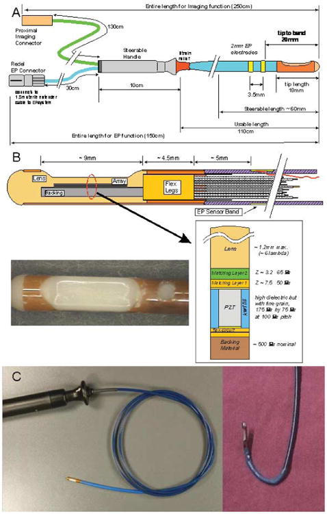
A, Functional dimensions of the 9F HS catheter. B, Tip region of the HS catheter. The flex folds back on itself at the distal tip so that there are actually 2 flex layers under the array with an adhesive layer between them. The photograph shows an HS catheter tip region with a “tapered” lens design. C, Our custom-designed ICE catheter. Left panel, Full device with a side view of the echo probe at the tip. Right panel, Steering capability of the tip.
Integration of EP Mapping Sensors
Several EP mapping sensor arrangements were implemented during catheter development. One design with which we have the most experience uses 2 sensor bands just proximal to the imaging array at the tip of the catheter. The sensor bands, as EP mapping electrodes, are able to sense local intracardiac potentials, providing valuable electrocardiographic data. The electrodes also serve another valuable function. They can, as well, provide EA position information regarding an applied electrical field gradient when the EA apparatus is used to track the 3D position of the catheter. The internal catheter wires for each of these bands are routed with good-quality electrical isolation to the EP connector separately connected to the EP monitor.
Steering
To enable bidirectional steering, 2 steering wires were needed in the catheter design. Each steering wire is housed in its own small lumen within the catheter shaft on opposite sides of the wall. The steering handle, together with a longitudinally firm catheter shaft, form the remainder of the mechanical steering system, which allows the sector image to be oriented on either the outside or inside radius of the catheter steering bend, 0° to 180° in both anteflex and retroflex directions on a 2.8-cm radius of curvature (Figure 2A). The image plane is essentially in the same plane as the steering bend. The torquability of the catheter shaft enables fine adjustment of image plane positioning.
Figure 2.
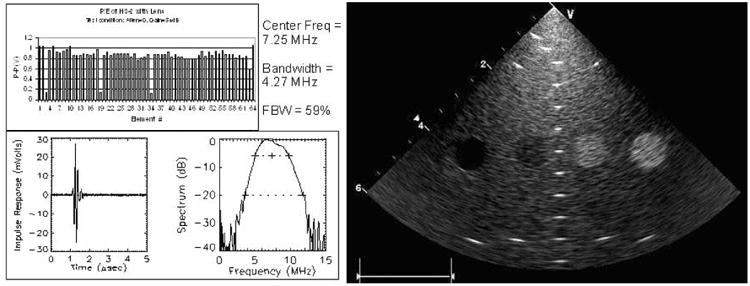
Individual element and resolution testing of our HS catheter.
Interconnect and Imaging Array Cable
The catheter was designed to use an imaging system connector with the necessary attributes of a small sterilizable disposable connector. This critical connection link to the imaging system should be small, inexpensive, and reliable and should possess a good retention force while also protecting user safety with recessed system-end live electrode contacts. A simple but very useful system interface called the interface box (I-box) was designed to allow a 2.5-m trunk cable connection to be made to the imaging system zero–insertion force connector. The I-box was designed with a 100-pin Samtec BSH series connector (Samtec, Inc, New Albany, IN) mounted directly to a well-shielded interconnect printed circuit board. A trunk cable was assembled with a shielded bundle of 40-American wire gauge (AWG) coaxial cables to link the I-Box with the system zero–insertion force connector.
The imaging array cable is a shielded bundle of 64 individual microcoaxes (Tyco Healthcare/Precision Interconnect, Wilsonville, OR) that is nominally 0.077 inches in diameter and occupies a large portion of the catheter shaft lumen. The individual coax members are made with a 48-AWG center conductor, 0.0013-inch fluoropolymer insulation, and a 52-AWG served shield offering better than 95% coverage with a 0.0006-inch polyester film covering that produces a total coax diameter of 0.0065 inches. The 64 coaxes are assembled together with 0.002-inch binder tape, 46-AWG shield braiding, and an additional 0.002-inch wrap of fluoropolymer tape. The characteristic impedance is 50 Ω.
Imaging Array Piezoelectric Design
The 64 piezoelectric array elements are arranged within the tip enclosure at the distal end of the catheter to form a side-looking image plane with a centered sector plane orthogonal to the catheter axis. The active imaging aperture is 2.6 mm in elevation and 6.4 mm in length with a 100-μm element pitch. At 7.5 MHz, the 2.6-mm elevation length provides a good passive focus for imaging in the 10- to 40-mm range, and phased array focusing in the image plane is designed to produce an azimuthal resolution close to 0.5 mm.
The piezoceramic array is made of a standard 2-2 composite with absorbing kerf fillers. To achieve a fractional bandwidth of greater than 50%, a double matching layer was used, with the first layer targeted to be 7.5 megarayls at 50 μm and the second layer 3.2 megarayls at 65 μm. The array assembly was bonded to a 25-μm polyimide flex circuit with a high-absorption backing. The flex circuit is folded on itself at the tip of the array to allow adequate paths for the 64-element connections so the flex is double layered under the lead-zirconate-titanate stack, as shown in Figure 1B.
Array characterization testing showed that, for imaging of in vitro phantoms with the array running on the Vivid 7 system, penetration to 8 to 9 cm could be achieved, usually at a transmit frequency of 8 to 10 MHz, and 13 to 15 MHz was best in the first 5 cm, with harmonic combinations also implemented for depths of less than 4 cm. The estimated lateral resolution was 0.2 mm at a depth of 4 to 6 cm.
The array lens material was selected to be a castable biocompatible polyurethane (RP6400; Freeman Mfg & Supply Co, Avon, OH) with an acoustic velocity as reasonably close to that of water as possible because the preferred round lens cross section would represent as much as a 6-lambda thickness at the thickest point in the round lens shape. Acoustic attenuation of this lens material is not inconsiderable at 10 dB · cm−1 · MHz−1 for 1-way transmission, significantly affecting the quality of the elevation beam shape. Both a minimally thick and flattened lens as well as a full round lens were used in our tests. Most of our catheters were built with the flat lens version. Laboratory testing resulted in early array prototypes with an average element center frequency of 7.25 MHz and a bandwidth of 4.27 MHz.
Of particular interest for this work were tissue Doppler imaging (TDI), TVI, SRI, and tissue synchronization imaging (TSI) to determine the direction of propagation of the contractile wave front. For TDI, the temporal and spatial averaging were both disabled during acquisition to obtain better images. The frame rate was maximized to 100 to 150 frames per second. An aliasing velocity for TDI was set at 10 to 16 cm/s, depending on wall motion velocity and depth. Three to 4 cardiac cycles were stored as digital scan line data for offline review in EchoPAC PC (GE Healthcare). The quality of images for different anatomic sites as well as TVI, SRI, and TSI was reviewed for analysis or TDI or for strain rate measures of mechanical action or rhythm propagation as well as non–angle-dependent 2D strain calculations derived from high–frame rate, high-frequency gray scale images, especially useful for looking at LV synchrony in multiple regions from the same images.
Pacing Methods
Because the HS catheters were capable of providing tissue Doppler strain rate regional wall mechanics observations, we wanted to verify that motion of the catheters did not preclude their use in detecting the origin and propagation of the cardiac rhythm or synchronization of the LV using mechanical indicators of the activation sequence; therefore, we also performed multisite pacing during these experiments.
Temporary epicardial pacing leads were placed on the epicardium. Temporary pacing electrodes (Ethicon, Inc, Somerville, NJ) were attached to the RA, RV, and LV lateral free wall or posterior wall to allow single-site or multisite pacing. Each animal underwent different combinations of the pacing for acquiring TDI data at a rate 10 to 20 beats per minute faster than their intrinsic sinus rhythm, with restorations of sinus rhythm between each pacing state. Pacing was performed with a temporary pacemaker (model 5388; Medtronic, Inc, Minneapolis, MN).
Imaging of EP Ablation in Open-Chest Pigs
Electrophysiology catheter placements were all guided by the ICE probes. Catheter ablation was performed with a Livewire catheter (4-mm tip; St Jude Medical Corp) several times during each animal study with a Stockert RF generator (Biosense-Webster, Inc, Diamond Bar, CA). The target temperature was 55°C, and the duration of delivery was 60 seconds, with power of 50 W. The imaging catheter devices were designed with special precautions to provide shielding from RF interference; observations of RF energy providing reverberations at the ablation catheter tip and the lack of RF distortion in the rest of the image were recorded during all ablation imaging.
NavX-Guided Ablation in 3 Closed-Chest Pigs
Last, we built 8 additional HS catheters with 2 additional electrodes, 1 proximal and 1 distal to the array, to facilitate integration of our catheter with the NavX 3D electrofield guidance system. Other than the additional electrodes proximal and distal to the array requiring additional shielded wires in the shaft, which made the catheter flexion segment slightly stiffer, the performance of these devices was identical to that of the previous prototypes.
In the 3 closed-chest pigs, HS catheters with extra electrodes proximal to the array could be integrated with NavX in a fusion display that detailed the anatomy of the ventricle where the separate 8F NavX electrofield navigation catheter had been placed (usually the LV), but it also showed the location of the HS catheter and any other catheters instantaneously.
Our goal was to examine whether this additional spatial localization could shorten the time necessary to perform 4 targeted ablations in each animal while visualizing the ablation with the HS catheters manipulated to image the ablation catheter and the adjacent region. The target ablation zones were the RA near the isthmus coronary sinus region, the RV apex, and along the right and the left sides of the septum. For this set of maneuvers, ablations were guided by unlimited fluoroscopy only and then repeated with primarily NavX guidance and limited fluoroscopy (2 or 3 short [<5-second] pulses) each for 12 ablations. Separate investigators manipulated the HS catheter and the ablation catheters from separate insertion sites in femoral veins or arteries, and we determined the time from placement of all of the catheters in the heart to the location of the tip of the ablation catheter, imaging of the ablation, and documentation of altered mechanics or intracardiac electrocardiographic recording with the HS catheter.
Results
Unique Views and Image Quality
The device could easily be manipulated throughout the right heart into locations for observing tricuspid, pulmonary, mitral, and aortic valve function in both the B-mode and the color Doppler mode (Figure 3). The combination of our unique arrays provided excellent image quality and, on the Vivid 7 architecture, frame rates of routinely more than 150 frames per second. The steerability of the device also allowed easy access to unique views, including views of the LV and mitral valve obtained by inserting the catheter into the coronary sinus and improved visualization of pulmonary veins by inserting the HS into the left pulmonary artery.
Figure 3.
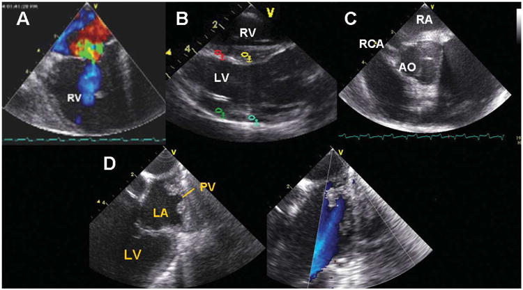
A, Tricuspid valve. B, Longitudinal view of the RV, LV, and LV outflow tract. C, Short axis view of the aortic valve (AO) and right coronary artery (RCA). D, B-mode image and color flow identification of a pulmonary vein (PV) imaged from the right side of the heart. LA indicates left atrium.
Also, the Vivid 7 platform has high–frame rate TDI and SRI capabilities, which were tested in studies of multisite pacing to document the positions of origin of arrhythmias and the effects of pacing on LV function and synchrony with RA, RA-RV, LV, and RA-LV pacing (Figure 4). In all animals, the entire LV could be imaged from the RA, and its synchrony could be evaluated in detail for all segments.
Figure 4.
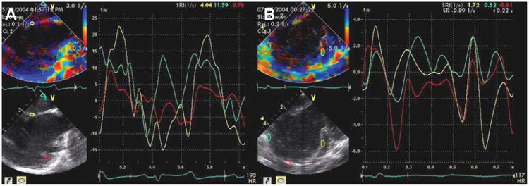
A, Normal sinus rhythm as assessed by the strain rate during intracardiac imaging. B, Left ventricular synchrony of the septum, lateral wall, and apex imaged from the RA. Turquoise indicates the RA wall; yellow, interatrial septum; and red, LV free wall.
Ablation Imaging
Figure 5A shows a fluoroscopic image just before the ablation to document and confirm the probe location. For RF delivery, a separate ablation catheter was used, inserted from the jugular vein through the SVC. Imaging of the ablation site during RF delivery was performed with the previously placed ICE probe. Imaging was also capable of showing complications. Figure 5B shows bubbles when the ablation pulse delivered was overheating.
Figure 5.
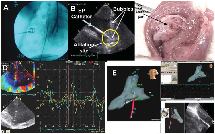
Ablation. A, Fluoroscopic image of the ablation probe position. B, Intracardiac echocardiography catheter–derived echo image of the ablation catheter. The green arrow indicates the ablation catheter; and yellow circle, ablation site with the catheter pointed toward it. The bubbles were shown when the RF pulse was delivered to the tissue. C, Fresh specimen of a pig heart after ablation. The arrow shows the ablation site on RV tissue. D, Change in the strain at the point of ablation as recorded during ablation; note the absence of RF interference. E, NavX 3D orientation of the position of the HS catheter (red), the ablation catheter (gray, left panel), and an ablation lesion imaged by ultrasound (right panel) as well as the EP waveform recording screen. ABL indicates ablation; AO, aorta; HS, HS catheter; and MA, mitral annulus.
These experiments showed that the imaging components of the catheter were shielded well enough from RF energy to be capable of providing high-resolution imaging for observing ablation locations during delivery of RF energy, which was detected with little RF interference in the images. During RF delivery a bright ghost image arising at the ablation tip and extending distally in the image occurred, but the interference was not enough to obscure detail in that area. Thus, imaging during ablation consistently showed the ablation electrode on the ablation catheter as well as a brightening of the texture at temperatures higher than 70°C and bubble formation during ablation. Figure 5C shows the discrete localized ablation site in one of the heart specimens after the ablation procedure. All 12 ablation sites were examined grossly.
Additional observations during ablation related to a thickening and brightening of surfaces extending along the tissue if the ablation catheter was pulled back to create a continuous lesion, thus verifying the adequacy and continuity of contact. Last, the mechanical changes associated with ablation could also be detected as changes in local strain mechanics at the area of ablation (Figure 5D).
Ablation Imaging Integrated With NavX: Visualization, Orientation, and Ease of Manipulating the HS and Ablation Catheters to Optimize Ablation Imaging
As stated in “Materials and Methods,” in the last 3 animals, ablation was performed while the imaging catheter and the ablation catheter were localized and guided by unlimited fluoroscopy and the ultrasound images or by short pulses of fluoroscopic and NavX guidance showing the positions of the HS and ablation catheters as well as the ultrasound images (Figure 5E). In each animal, 4 ablations (2 isthmuses, an RV ablation, and an LV ablation) were performed under ultrasound visualization with fluoroscopic localization, and 4 other ablations were performed with ultrasound imaging orienting the ablations and HS catheters on the NavX display only. One investigator manipulated the ablation catheter, and another investigator manipulated the HS catheter. The time to position both in all 3 locations from a neutral position in the RA and to perform the 4 ablations under ultrasound visualization was recorded within the NavX console computer. The mean time ± SD for positioning the catheters with fluoroscopy and performing the 4 ablations in each pig was 23 ± 5.2 minutes with fluoroscopy only, and it was 17 ± 3.5 minutes with NavX and very limited short pulses of fluoroscopy.
Discussion
This new EP-targeted ultrasound device combines full-function intracardiac ultrasound diagnosis along with EP recording and integration with the NavX system for EP guidance in 1 catheter. Although it can be advanced to perform ablation with the RF electrode at its tip (because it is side looking), this study was mostly designed to evaluate its ability to image ablation being performed with other RF catheters.
Advantages
From our initial observations, this device has all the imaging capabilities that AcuNav has but is more flexible (0°–180° flex) and thus easier to manipulate and position. Tissue velocity imaging and SRI can provide an integrated electrical-plus-mechanical activation map of the myocardium, showing changes that occur with ablation as well as with pacing resynchronization. Offline non–angle-dependent methods for evaluation of cardiac mechanics, such as the non–angle-dependent speckle-tracking 2D strain methods gaining so much attention in the EP and cardiac function literature, are also quickly computed in the procedure room.
The more effective shielding from RF interference we have developed for this device allows imaging with minimal loss of image quality during RF ablation so that the physician can visualize the lesion, anatomically monitor the ablation procedure and the degree of contact between the catheter and tissue, and detect the distribution of textural and mechanical changes during RF delivery. This may reduce the need for fluoroscopy and x-ray exposure. The capabilities of the motion detection methods TDI, SRI, and TSI also aid in resynchronization to localizing and testing the effect of resynchronization-pacing electrodes or as a method for shortening the time needed to determine the site of origin of arrhythmias.
Last, while a device that is side looking is not, in concept, different from the existing commercially available imaging catheters, although we have improved image quality, frame rate, ease of manipulation, and shielding, a side-looking device may be more cumbersome to aim at a specific area because rotational position is a hard parameter to control on a curved tube.
Therefore, we include mention of the second device in our National Heart, Lung, and Blood Institute–sponsored research partnership: an EP-enabled catheter with a 24-element array on the tip of the catheter, a center frequency of 14 MHz, and an array pitch of 0.065; elements are 1.2 mm in elevation, with extreme agility. This device has testing and NavX integration electrodes on the shaft and an ablation electrode on the tip set forward and thermally isolated from the imaging the array. We have named this device the microlinear array, and it is designed for near-field imaging (Figure 6).
Figure 6.
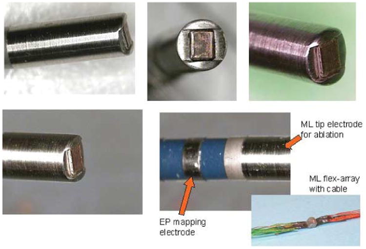
Tip of the forward-looking microlinear catheter. The array is thermally and electrically isolated from the surrounded ablation face at the tip.
Limitations
Our study involved pig experiments either with or without fluoroscopy. These studies were done on the prototype devices and were basically observational only. In addition, we did not do a study of the stability of HS or ablation catheter positioning with fluoroscopy. Further optimization of the lens structure and bandwidth as well as scanner parameters should improve the frequency range and resolution as well as TDI and SRI quality.
Conclusions
Our HS ICE catheters are capable of providing high-quality imaging of cardiac structures with good penetration and very high resolution. The TDI SRI function has the potential to determine ectopic rhythm origination sites and aid evaluation of ventricular synchrony. Integration of the catheters with the 3D image fusion modality provided by NavX should aid their implementation into the complicated procedures that constitute modern invasive arrhythmia treatment, in which they may aid performance of, understanding of, and assessment of ablation.
Acknowledgments
This research was supported by National Heart, Lung, and Blood Institute Bioengineering Research Partnership grant R01 HL67647. Drs Thomenius and Dentinger are employees of GE Global Research, and Dr Chia is a vice president at Irvine Biomedical, Inc; they are also among the partners to the grant.
Abbreviations
- AWG
American wire gauge
- EA
electroanatomic
- EP
electrophysiology
- HS
hockey stick
- I-box
interface box
- ICE
intracardiac echocardiography
- LV
left ventricular
- RA
right atrial
- RF
radio frequency
- RV
right ventricular
- SRI
strain rate imaging
- 3D
3-dimensional
- TDI
tissue Doppler imaging
- TSI
tissue synchronization imaging
- TVI
tissue velocity imaging
- 2D
2-dimensional
References
- 1.Jackman WM, Wang X, Friday KJ, et al. Catheter ablation of accessory atrioventricular pathways (Wolff-Parkinson-White syndrome) by radiofrequency current. N Engl J Med. 1991;324:1605–1611. doi: 10.1056/NEJM199106063242301. [DOI] [PubMed] [Google Scholar]
- 2.Lesh MD, Van Hare GF, Schamp DJ, et al. Curative percutaneous catheter ablation using radiofrequency energy for accessory pathways in all locations: results in 100 consecutive patients. J Am Coll Cardiol. 1992;19:1303–1309. doi: 10.1016/0735-1097(92)90338-n. [DOI] [PubMed] [Google Scholar]
- 3.Kugler JD, Danford DA, Houston K, Felix G. Radiofrequency catheter ablation for paroxysmal supraventricular tachycardia in children and adolescents without structural heart disease. Pediatric EP Society, Radiofrequency Catheter Ablation Registry. Am J Cardiol. 1997;80:1438–1443. doi: 10.1016/s0002-9149(97)00736-4. [DOI] [PubMed] [Google Scholar]
- 4.Lesh MD, Van Hare GF, Epstein LM, et al. Radiofrequency catheter ablation of atrial arrhythmias: results and mechanisms. Circulation. 1994;89:1074–1089. doi: 10.1161/01.cir.89.3.1074. [DOI] [PubMed] [Google Scholar]
- 5.Ernst S, Schlüter M, Ouyang F, et al. Modification of the substrate for maintenance of idiopathic human atrial fibrillation: efficacy of radiofrequency ablation using nonfluoroscopic catheter guidance. Circulation. 1999;100:2085–2092. doi: 10.1161/01.cir.100.20.2085. [DOI] [PubMed] [Google Scholar]
- 6.Kalman JM, Van Hare GF, Olgin JE, Saxon LA, Stark SI, Lesh MD. Ablation of “incisional” reentrant atrial tachycardia complicating surgery for congenital heart disease: use of entrainment to define a critical isthmus of conduction. Circulation. 1996;93:502–512. doi: 10.1161/01.cir.93.3.502. [DOI] [PubMed] [Google Scholar]
- 7.Van Hare GF, Lesh MD, Stanger P. Radiofrequency catheter ablation of supraventricular arrhythmias in patients with congenital heart disease: results and technical considerations. J Am Coll Cardiol. 1993;22:883–890. doi: 10.1016/0735-1097(93)90207-h. [DOI] [PubMed] [Google Scholar]
- 8.Case CL, Gillette PC, Oslizlok PC, Knick BJ, Blair HL. Radiofrequency catheter ablation of incessant, medically resistant supraventricular tachycardia in infants and small children. J Am Coll Cardiol. 1992;20:1405–1410. doi: 10.1016/0735-1097(92)90255-l. [DOI] [PubMed] [Google Scholar]
- 9.Epstein LM, Chiesa N, Wong MN, et al. Radiofrequency catheter ablation in the treatment of supraventricular tachycardia in the elderly. J Am Coll Cardiol. 1994;23:1356–1362. doi: 10.1016/0735-1097(94)90377-8. [DOI] [PubMed] [Google Scholar]
- 10.Gornick CC, Adler SW, Pederson B, Hauck J, Budd J, Schweitzer J. Validation of a new noncontact catheter system for electroanatomic mapping of left ventricular endocardium. Circulation. 1999;99:829–835. doi: 10.1161/01.cir.99.6.829. [DOI] [PubMed] [Google Scholar]
- 11.Cosio FG, Lopez-Gil M, Goicolea A, Arribas F, Barroso JL. Radiofrequency ablation of the inferior vena cava-tricuspid valve isthmus in common atrial flutter. Am J Cardiol. 1993;71:705–709. doi: 10.1016/0002-9149(93)91014-9. [DOI] [PubMed] [Google Scholar]
- 12.Calkins H, Niklason L, Sousa J, el-Atassi R, Langberg J, Morady F. Radiation exposure during radiofrequency catheter ablation of accessory atrioventricular connections. Circulation. 1991;84:2376–2382. doi: 10.1161/01.cir.84.6.2376. [DOI] [PubMed] [Google Scholar]
- 13.Jue J, Lesh M, Ossipov M, Sudhir K, Fitzgerald P, Yock P. Real-time quantification of radiofrequency ablation injury using a 15-MHz intracardiac imaging catheter [abstract] Circulation. 1992;86:I-784. [Google Scholar]
- 14.Avitall B, Hare J, Khan M, Lessila C, Krum D. Monitoring lesion formation and endocardial damage during radiofrequency ablation using intracardiac/intravascular ultrasound [abstract] Circulation. 1992;86:I-192. [Google Scholar]
- 15.Schwartz SL, Pandian NG, Kusay BS, et al. Real-time intracardiac two-dimensional echocardiography: an experimental study of in vivo feasibility, imaging planes, and echocardiographic anatomy. Echocardiography. 1990;7:443–455. doi: 10.1111/j.1540-8175.1990.tb00385.x. [DOI] [PubMed] [Google Scholar]
- 16.Seward JB, Khandheria BK, McGregor CG, Locke TJ, Tajik AJ. Transvascular and intracardiac two-dimensional echocardiography. Echocardiography. 1990;7:457–464. doi: 10.1111/j.1540-8175.1990.tb00386.x. [DOI] [PubMed] [Google Scholar]
- 17.Schwartz SL, Pandian NG, Hsu TL, Weintraub A, Cao QL. Intracardiac echocardiographic imaging of cardiac abnormalities, ischemic myocardial dysfunction, and myocardial perfusion: studies with a 10 MHz ultrasound catheter. J Am Soc Echocardiogr. 1993;6:345–355. doi: 10.1016/s0894-7317(14)80233-2. [DOI] [PubMed] [Google Scholar]
- 18.Hung JS, Fu M, Yeh KH, Chua S, Wu JJ, Chen YC. Usefulness of intracardiac echocardiography in transseptal puncture during percutaneous transvenous mitral commissurotomy. Am J Cardiol. 1993;72:853–854. doi: 10.1016/0002-9149(93)91084-u. [DOI] [PubMed] [Google Scholar]
- 19.Schwartz SL, Pandian NG, Crowley R, Kumar R. Intracardiac echocardiography without fluoroscopy: potential of a balloon-tipped, flow-directed ultrasound catheter. Am Heart J. 1995;129:598–603. doi: 10.1016/0002-8703(95)90290-2. [DOI] [PubMed] [Google Scholar]
- 20.Jiang L, Weissman NJ, Guerrero JL, et al. Percutaneous transvenous intracardiac ultrasound imaging in dogs: a new approach to monitor left ventricular function. Heart. 1996;76:442–448. doi: 10.1136/hrt.76.5.442. [DOI] [PMC free article] [PubMed] [Google Scholar]
- 21.Hung JS, Fu M, Yeh KH, Wu CJ, Wong P. Usefulness of intracardiac echocardiography in complex transseptal catheterization during percutaneous transvenous mitral commissurotomy. Mayo Clin Proc. 1996;71:134–140. doi: 10.4065/71.2.134. [DOI] [PubMed] [Google Scholar]
- 22.Spencer KT, McKay CR, Kerber RE. Intracardiac ultrasound detection of right ventricular infarction in a canine model. J Am Soc Echocardiogr. 1997;10:352–356. doi: 10.1016/s0894-7317(97)70072-5. [DOI] [PubMed] [Google Scholar]
- 23.Tardif JC, Cao QL, Schwartz SL, Pandian NG. Intracardiac echocardiography with a steerable low-frequency linear-array probe for left-sided heart imaging from the right side: experimental studies. J Am Soc Echocardiogr. 1995;8:132–138. doi: 10.1016/s0894-7317(05)80402-x. [DOI] [PubMed] [Google Scholar]
- 24.Hynes BJ, Mart C, Artman S, Pu M, Naccarelli GV. Role of intracardiac ultrasound in interventional electrophysiology. Curr Opin Cardiol. 2004;19:52–57. doi: 10.1097/00001573-200401000-00011. [DOI] [PubMed] [Google Scholar]