Abstract
The structure of the foramen ovale of the sphenoid bone is clinically important, particularly with regard to surgical procedures that cannulate of the foramen such as percutaneous trigeminal rhizotomy for the treatment of trigeminal neuralgia, percutaneous biopsy of parasellar lesions, and electroencephalographic analysis of the temporal lobe among patients undergoing selective amygdalohippocampectomy. Differences in the morphology of the FO have been reported to contribute to difficulties in the cannulation of the FO. However, reports regarding the structure of the FO use subjective and ambiguous descriptions of morphology including “oval”, “truly oval”, “elongated oval”, “elongated”, “semicircular”, “almond”, “round”, “rounded”, “slit”, “irregular”, “D shape”, and “pear.” Therefore, it is necessary to describe the structure of the FO with reproducible objective morphometric data. This study analyzed 169 foramina to determine normative morphometric shape descriptions of the following: area, perimeter, circularity, solidity, axes of a best fit ellipse, aspect ratio, and roundness. The shape descriptors reported herein may aid in identification and description of structural variation in FO including bony projections encroaching upon the foramina and may improve surgical approaches to transovale cannulation.
Keywords: anatomic variation, cannulation, skull base, stereotactic surgery, trigeminal neuralgia
Introduction
The foramen ovale (FO) of the sphenoid bone is located anteromedial to the foramen spinosum (FS) and posterolateral to the foramen rotundum.1 The FO transmits numerous anatomical structures including the mandibular branch of the trigeminal nerve (V3), accessory middle meningeal artery, and sometimes the lesser petrosal nerve, emissary veins, and the anterior trunk of the middle meningeal sinus.2–3 The FO has variable morphology. In some cases the border of the FO is irregular and sometimes incisures are visible along its edges.4 Likewise, bony spurs, spines, tubercles, plates, etc. have been noted to project into the FO.5–8 Occasionally the FO is separated into two or three separate compartments, sometimes separated by thin bony spicules, most often occurring in one common osseous niche.1,4,6,8 The FO has also been reported to be absent from one side of the sphenoid bone.8 Also, the FO may be confluent with the FS.8
Although there is great variety in the morphology of the FO, when an enlargement of the FO occurs, neurinoma of the trigeminal nerve and parasellar tumors should be considered in a differential diagnosis.9–10 The structure of the FO is also particularly important with regard to surgical procedures that cannulate the foramen such as percutaneous trigeminal rhizotomy for the treatment of trigeminal neuralgia,11–12 percutaneous biopsy of parasellar lesions,10,13–14 electroencephalographic analysis of the temporal lobe among patients undergoing selective amygdalohippocampectomy.15 Moreover, differences in the morphology of the FO have been reported to contribute to difficulties in the cannulation of the foramen.16
The morphology of the FO has been described by numerous subjective or otherwise ambiguous terms including “oval”, “truly oval”, “elongated oval”, “elongated”, “semicircular”, “almond”, “round”, “rounded”, “slit”, “irregular”, “D shape”, and “pear”.1,5–8,17–19 The prevalence of the aforementioned morphological variations can be found in Table 1. With regard to morphometrics - length, width, and area are the parameters which have typically been reported in the literature.
Table 1.
Morphology of the foramen ovale according to studies utilizing various subjective and ambiguous nomenclatures.
| Authors | Shape | Sex | Right | Left | Total (R + L) | |||
|---|---|---|---|---|---|---|---|---|
| N | % | N | % | N | % | |||
| Berlis et al (1992)1 | Truly oval | − | − | − | − | − | − | 56.7 |
| Elongated oval | − | − | − | − | − | − | 31.7 | |
| Semicircular | − | − | − | − | − | − | 11.7 | |
| Ray et al (2005)5 | Oval | − | 22 | 62.8 | 21 | 60 | 43 | 61.4 |
| Almond | − | 11 | 31.4 | 13 | 37.1 | 24 | 34.2 | |
| Round | − | 1 | 2.8 | 1 | 2.8 | 2 | 2.8 | |
| Slit | − | 1 | 2.8 | 0 | 0 | 1 | 1.4 | |
| Somesh et al (2011)7 | Oval | − | 48 | 58.53 | 45 | 54.87 | 93 | 56.70 |
| Almond | − | 24 | 29.26 | 23 | 28.04 | 47 | 28.65 | |
| Round | − | 8 | 9.75 | 10 | 12.19 | 18 | 10.97 | |
| Irregular | − | 2 | 2.43 | 4 | 4.87 | 6 | 3.65 | |
| Daimi et al (2011)6 | D shape | − | − | − | − | − | − | 46.16 |
| Oval | − | − | − | − | − | − | 29.87 | |
| Rounded | − | − | − | − | − | − | 12.52 | |
| Elongated | − | − | − | − | − | − | 10.41 | |
| Slit | − | − | − | − | − | − | 1.04 | |
| Wadhwa et al (2012)17 | Oval | − | 19 | − | 23 | − | 42 | − |
| Almond | − | 6 | − | 3 | − | 9 | − | |
| Round | − | 3 | − | 3 | − | 6 | − | |
| Slit | − | 2 | − | 1 | − | 3 | − | |
| Gupta & Rai (2013)18 | Oval | − | 20 | 57.14 | 18 | 51.43 | 38 | 54.29 |
| Almond | − | 14 | 40.00 | 11 | 31.43 | 25 | 35.71 | |
| Round | − | 1 | 2.86 | 5 | 14.29 | 6 | 8.57 | |
| Slit | − | 0 | 0.00 | 1 | 2.86 | 1 | 1.43 | |
| Kahairnar & Bhusari (2013)8 | Oval | M | 55 | 78.5 | 54 | 77.1 | − | 76.5 |
| F | 23 | 76.6 | 21 | 70.0 | − | |||
| Almond | M | 6 | 8.5 | 9 | 12.9 | − | 10.5 | |
| F | 3 | 10.0 | 3 | 10.0 | − | |||
| Round | M | 5 | 7.1 | 5 | 7.1 | − | 7.0 | |
| F | 1 | 3.3 | 3 | 10.0 | − | |||
| Slit | M | 4 | 5.7 | 2 | 2.9 | − | 6.0 | |
| F | 3 | 10.0 | 3 | 10.0 | − | |||
| Patil et al (2014)19 | Oval | − | 40 | − | 44 | − | 84 | 70 |
| Almond | − | 4 | − | 2 | − | 6 | 5.0 | |
| Round | − | 9 | − | 7 | − | 16 | 13.33 | |
| Slit | − | 4 | − | 5 | − | 9 | 7.5 | |
| Pear | − | 3 | − | 2 | − | 5 | 4.17 | |
Hyphen “-“ designates information that was not included by the original report.
The structure of the FO is clinically important; however, descriptive terms used to describe its structure are largely subjective and ambiguous. Likewise, length, width, and area provide an incomplete morphometric representation of the FO. Therefore, this study assesses the structure of the FO with regard to objective shape characteristics including circularity, roundness, solidity, length measurements of major and minor axes of a best fit ellipse, aspect ratio of a best fit ellipse, in addition to the area contained within the FO and the perimeter of the FO.
Materials and Methods
The study analyzed FO from 91 dry adult sphenoid bones of undetermined age-at-death, sex, and race from West Liberty University, West Virginia University School of Medicine, Franciscan University of Steubenville, Ohio University – Eastern, Bethany College, and Washington & Jefferson College. Some sphenoid bones were hemissected and therefore researchers were not always able to analyze foramina bilaterally. FO which were confluent with the FS were excluded from the study. A total of 169 FO were analyzed (83 left-sided FO and 86 right-sided FO).
Digital calipers (Mitutoyo 0–8 in (0–203.2mm) ABSOLUTE™ digimatic caliper series 500, accuracy ± 0.001 in (0.025 mm)) were fixed to a known distance of 5.00 mm, held flush to the FO, and then macrophotography was performed with a digital camera (Canon PowerShot SX50 HS, 12.1 Megapixel). Digital pictures were then assessed with the built-in functions of ImageJ software (NIH) by using the 5.00 mm calibration as a reference. Measurements were taken of the following parameters: area contained within the foramen, perimeter of the foramen, circularity, and solidity. Additionally, the axes and aspect ratio of a best fit ellipse as well as roundness were calculated.
Circularity
Circularity is a shape descriptor that can mathematically indicate the degree of similarity to a perfect circle. A value of 1.0 designates a perfect circle. As the circularity value approaches 0.0, the shape is increasingly less circular. Circularity can be defined by the equation:
Solidity
Solidity describes the extent to which a shape is convex or concave. Taking the area within the foramen and dividing it by the area enclosed by a convex hull can provide information regarding the solidity of the shape. A convex hull can be seen in Figure 1. The solidity of a completely convex shape is 1, the farther the solidity deviates from 1, the greater the extent of concavity in the structure. Solidity can be defined by the equation:
Figure 1.
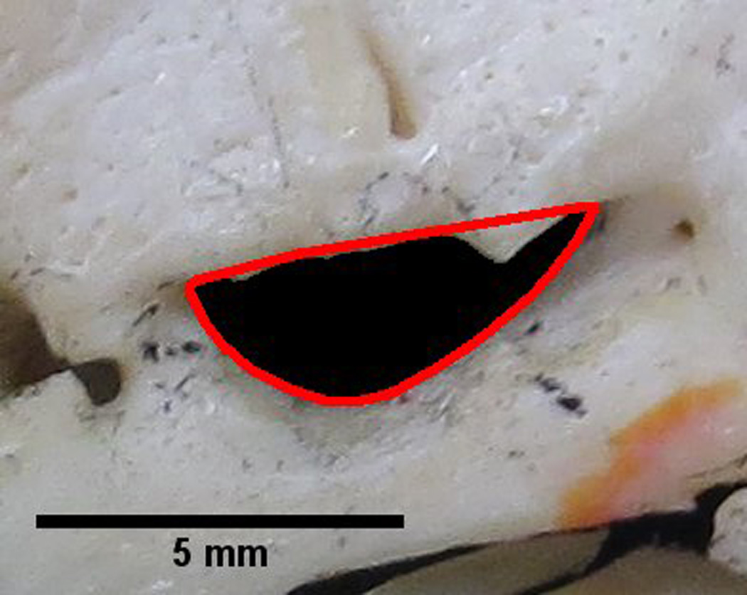
Foramen ovale outlined by a red convex hull. The solidity of the foramen can be determined by dividing the area within the foramen by the area contained within the convex hull. A perfectly convex shape has a solidity of 1. This image illustrates a foramen with a solidity of 0.87. Therefore, certain parts of the foramen outline are convex. These convexities may indicate bony structures projecting into the foramen, which can be visualized in the figure. The measurement of solidity may aid in identification of bony projections encroaching upon the foramen.
Axes and Aspect Ratio of a Best Fit Ellipse
Also, using the internal features of ImageJ, a best fit ellipse was also fit to each FO (Figure 2). From the best fit ellipse the following parameters were assessed: length measurements of major and minor axes and the aspect ratio (Figure 2). The aspect ratio can be characterized by the following equation
Figure 2.
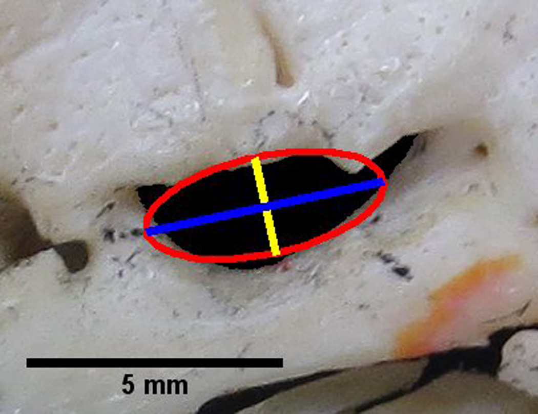
Foramen ovale with an overlay of a best fit ellipse (red), the major axis of the best fit ellipse (blue) and the minor axis of the best fit ellipse (yellow). The major axis is also utilized in the determination of roundness.
Roundness
Roundness is similar to circularity but is insensitive to irregular borders along the perimeter of the foramen. Roundness also takes into consideration the major axis of the best fit ellipse. Roundness can be defined by the equation:
Descriptive and inferential statistics were calculated using the statistical software Statistical Package for the Social Sciences (IBM SSPS Statistics 20). Graphical representation of the data was produced with GraphPad Prism statistical software, version 6.00 (GraphPad Software, La Jolla, CA, USA).
Results
Descriptive statistics (Mean, SD, SEM, Min, Max, and Range) characterizing the shapes of the FO can be found in Table 2. A summary of the differences between paired left- and right-sided foramina can be found in Table 3.
Table 2.
Normative morphometric shape descriptor descriptive statistics of the foramen ovale.
| Side(s) | Mean | SD | SEM | Minimum | Maximum | Range | |
|---|---|---|---|---|---|---|---|
| Area (mm2) | L | 14.39 | 4.66 | 0.50 | 7.34 | 28.69 | 21.35 |
| R | 16.55 | 5.32 | 0.58 | 5.58 | 30.50 | 24.92 | |
| L & R | 15.45 | 5.09 | 0.39 | 5.58 | 30.50 | 24.92 | |
| Perimeter (mm) | L | 17.54 | 3.41 | 0.37 | 11.94 | 30.42 | 18.49 |
| R | 18.92 | 3.47 | 0.38 | 11.88 | 28.74 | 16.87 | |
| L & R | 18.22 | 3.50 | 0.27 | 11.88 | 30.42 | 18.55 | |
| Circularity | L | 0.60 | 0.12 | 0.012 | 0.28 | 0.84 | 0.56 |
| R | 0.58 | 0.10 | 0.011 | 0.36 | 0.81 | 0.45 | |
| L & R | 0.59 | 0.11 | 0.008 | 0.28 | 0.84 | 0.56 | |
| Solidity | L | 0.95 | 0.03 | 0.003 | 0.78 | 0.99 | 0.21 |
| R | 0.95 | 0.03 | 0.003 | 0.86 | 0.99 | 0.12 | |
| L & R | 0.95 | 0.03 | 0.002 | 0.78 | 0.99 | 0.21 | |
| Major Axis (mm)* | L | 5.99 | 1.08 | 0.12 | 4.00 | 10.14 | 6.14 |
| R | 6.62 | 1.12 | 0.12 | 3.87 | 10.46 | 6.59 | |
| L & R | 6.30 | 1.14 | 0.09 | 3.87 | 10.46 | 6.59 | |
| Minor Axis (mm)* | L | 3.02 | 0.63 | 0.07 | 1.82 | 5.53 | 3.71 |
| R | 3.13 | 0.66 | 0.07 | 1.70 | 4.67 | 2.97 | |
| L & R | 3.07 | 0.64 | 0.05 | 1.70 | 5.53 | 3.83 | |
| Aspect Ratio* | L | 2.04 | 0.42 | 0.05 | 1.19 | 3.18 | 1.99 |
| R | 2.17 | 0.44 | 0.05 | 1.40 | 3.78 | 2.38 | |
| L & R | 2.11 | 0.43 | 0.03 | 1.19 | 3.78 | 2.59 | |
| Roundness* | L | 0.51 | 0.11 | 0.012 | 0.32 | 0.84 | 0.52 |
| R | 0.48 | 0.09 | 0.010 | 0.27 | 0.72 | 0.45 | |
| L & R | 0.50 | 0.10 | 0.008 | 0.27 | 0.84 | 0.57 |
: calculated, in whole or part, from a best fit ellipse
Table 3.
Comparison between left- and right-sided foramina ovalae via paired t-tests.
| Paired Differences | T | df | P | |||||
|---|---|---|---|---|---|---|---|---|
| Mean | SD | SEM | 95% CI | |||||
| Lower | Upper | |||||||
| R – L Area | 2.18 | 4.83 | 0.54 | 1.10 | 3.25 | 4.04 | 79 | 0.000125* |
| R – L Perimeter | 1.37 | 3.66 | 0.41 | 0.56 | 2.18 | 3.35 | 79 | 0.001240* |
| R – L Major Axis† | 0.61 | 1.08 | 0.12 | 0.37 | 0.85 | 5.04 | 79 | 0.000003* |
| R – L Minor Axis† | 0.12 | 0.61 | 0.07 | −0.02 | 0.26 | 1.74 | 79 | 0.085119 |
| R – L Circularity | −0.01 | 0.12 | 0.01 | −0.04 | 0.01 | −0.94 | 79 | 0.350326 |
| R – L Aspect Ratio† | 0.12 | 0.44 | 0.05 | 0.02 | 0.22 | 2.40 | 79 | 0.018942* |
| R – L Roundness† | −0.03 | 0.12 | 0.01 | −0.05 | −0.01 | −2.56 | 79 | 0.012339* |
| R – L Solidity | −0.001 | 0.03 | 0.004 | −0.01 | 0.01 | −0.28 | 79 | 0.781632 |
: p < 0.05
: calculated, in whole or part, from a best fit ellipse
Area
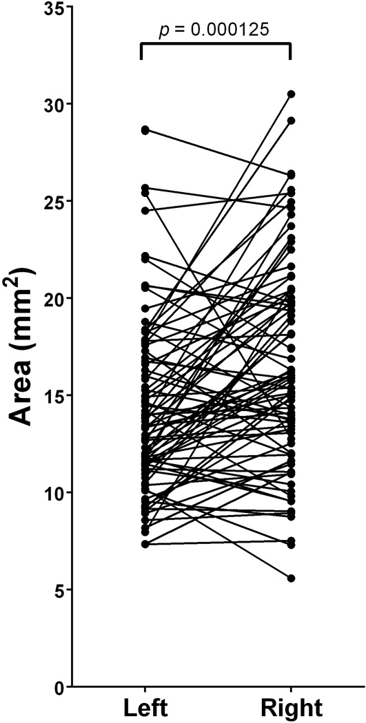
The average area contained within the FO (n=169) was 15.45 ± 5.09mm2 (Mean ± SD). Left-sided FO (n=86) were found to have an average area of 14.39 ± 4.66mm2 and right-sided FO were found to have an average area of 16.55 ± 5.32mm2 (Table 2). A paired t-test revealed a statistically significant difference between the areas of paired left and right-sided FO (t(79)=4.04; p=0.000125)(Figure 3, Table 3)
Figure 3.
Paired differences between left- and right-sided foramina ovalae reveal a significant difference in area (t(79)=4.04; p=0.000125). The right-sided foramina had, on average, an area that was 2.18 ± 4.83mm2 greater than that of left-sided foramina.
Perimeter
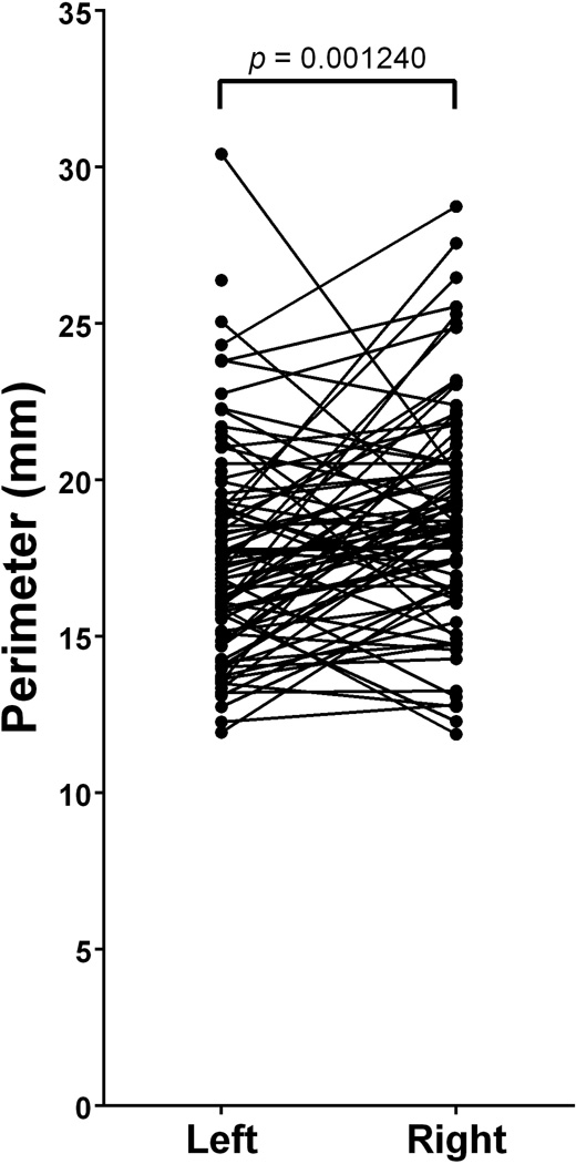
The average perimeter of the bony margin of the FO (n=169) was 18.22 ± 3.50mm (Mean ± SD). Left-sided FO (n=86) were found to have an average perimeter of 17.54 ± 3.41mm and right-sided FO were found to have an average perimeter of 18.92 ± 3.47mm (Table 2). A paired t-test revealed a statistically significant difference between the perimeters of paired left- and right-sided FO (t(79)=3.35; p=0.001240)(Figure 4, Table 3)
Figure 4.
Paired differences between left- and right-sided foramina ovalae reveal a significant difference in perimeter (t(79)=3.35; p=0.001240). The right-sided foramina had, on average, a perimeter that was 1.37 ± 3.66mm greater than that of left-sided foramina.
Major axis, minor axis, and aspect ratio of a best fit ellipse
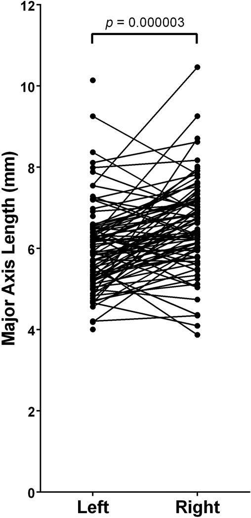
Among the total sample of FO studied, the average major and minor axes of best fit ellipses were 6.30 ± 1.14mm and 3.07 ± 0.64mm (Mean ± SD), respectively. Left-sided FO (n=86) were found to have an major and minor axes averaging 5.99 ± 1.08mm and 3.02 ± 0.63mm, respectively. Right-sided FO were found to have major and minor axes averaging 6.62 ± 1.12mm and 3.13 ± 0.66mm, respectively (Table 2). Paired t-tests revealed a statistically significant difference between the major axes of paired left- and right-sided FO (t(79)=5.04; p=0.000003)(Figure 5, Table 3). However, the minor axes of left and right-sided FO were not statistically different (t(79)=1.74; p=0.085119).
Figure 5.
Paired differences between left- and right-sided foramina ovalae reveal a significant difference in major axis length derived from a best fit ellipse (t(79)=5.04; p=0.000003). The right-sided foramina had, on average, a major axis length that was 0.61 ± 1.08mm greater than that of left-sided foramina.
The average aspect ratio of the fitted ellipses (i.e. [Major axis]/[Minor axis]) among the total sample of FO (n=169) was 2.11 ± 0.43 (Mean ± SD). Left-sided FO (n=86) were found to have an average aspect ratio of 2.04 ± 0.42 and right-sided FO were found to have an average aspect ratio of 2.17 ± 0.44 (Table 2). A paired t-test revealed a statistically significant difference between the aspect ratios of paired left- and right-sided FO (t(79)=2.40; p=0.018942)(Figure 6, Table 3)
Figure 6.
Paired differences between left- and right-sided foramina ovalae reveal a significant difference in the aspect ratio of a best fit ellipse (t(79)=2.40; p=0.018942). The right-sided foramina had, on average, an aspect ratio that was 0.12 ± 0.44mm greater than that of left-sided foramina.
Circularity
The average circularity among all FO (n=169) was 0.59 ± 0.11 (Mean ± SD). Left-sided FO (n=86) were found to have an average circularity of 0.60 ± 0.12 and right-sided FO were found to have an average circularity of 0.58 ± 0.10 (Table 2). There was no significant difference between the circularity of paired left- and right-sided FO (t(79)=0.94; p=0.350326)(Table 3)
Roundness
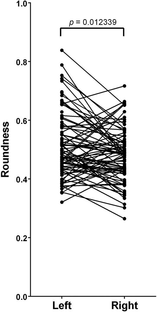
The average roundness among all FO (n=169) was 0.50 ± 0.10 (Mean ± SD). Left-sided FO (n=86) were found to have an average roundness of 0.51 ± 0.11 and right-sided FO were found to have an average roundness of 0.48 ± 0.09 (Table 2). There was a significant difference between the roundness of paired left- and right-sided FO (t(79)=−2.56; p=0.012339)(Figure 7, Table 3)
Figure 7.
Paired differences between left- and right-sided foramina ovalae reveal a significant difference in roundness (t(79)= −2.56; p=0.012339). The right-sided foramina had, on average, a roundness that was 0.03 ± 0.12 less than that of left-sided foramina.
Solidity
The average solidity among all FO (n=169) was 0.95 ± 0.02 (Mean ± SD). Both the left-sided FO (n=86) and the right-sided FO were found to have the same average solidity of 0.95 ± 0.03 (Table 2). There was no significant difference between the solidity of paired left- and right-sided FO (t(79)= −0.28; p=0.781632)(Table 3)
Discussion
Prior reports describing the morphology of the foramen ovale have utilized inconsistent, ambiguous, subjective nomenclature including “oval”, “truly oval”, “elongated oval”, “elongated”, “semicircular”, “almond”, “round”, “rounded”, “slit”, “irregular”, “D shape”, and “pear”.1,5–8,17–19 Likewise, reports have provided morphometric data limited to the parameters length, width, and area. This study is the first to determine the morphometric shape descriptors of circularity, solidity, major and minor axes of a best fit ellipse, aspect ratio of a best fit ellipse and roundness of the foramen ovale.
Understanding the shape of the foramen ovale is of particular clinical importance. This study has noted small, though significant differences between the area and perimeters of the FO. Likewise, the study has identified significant differences between paired left- and right-sided major and minor axes, aspect ratio, and roundness. No statistically significant differences were found between paired circularity and solidity measurements. Therefore, when investigating the possibility for pathology in the region of the FO, a bilateral comparison of FO shape, taking into consideration shape descriptors presented in this study may aid in identification of pathologic changes. When an enlargement of the FO occurs, neurinoma of the trigeminal nerve and parasellar tumors should be considered in a differential diagnosis.9–10
Cannulation of the foramen ovale is utilized in percutaneous trigeminal rhizotomy for the treatment of trigeminal neuralgia,11–12 percutaneous biopsy of parasellar lesions,10,13–14 and electroencephalographic analysis of the temporal lobe among patients undergoing selective amygdalohippocampectomy.15 The shape of the foramen may be important in determining the appropriate caliber of a stylet that could be transmitted through the FO. Indeed, differences in the morphology of the FO have been reported to contribute to difficulties in the cannulation of the foramen.16
One such morphological difference that may lead to surgical difficulty is a simple bony projection within the foramina. Solidity is a particular shape descriptor that would be capable of reflecting a bony projection into a foramen. The solidity of a completely convex shape is 1.0 and the farther the solidity deviates from 1, the greater the extent of concavity in the structure. Therefore, bony projections into the foramen would cause solidity values to deviate from 1.0. This report identified an average solidity of 0.95 ± 0.03 (Mean ± SD) with a minimum solidity of 0.78 and a maximum solidity of 0.99.
Anatomists and clinicians should be aware of the benefit of shape descriptor data, such as that presented herein, when evaluating the anatomy of the foramen ovale. The shape descriptors presented in this report may aid in identification and description of structural variation in FO including bony projections encroaching upon the foramina and may improve surgical approaches to transovale cannulation.
Acknowledgements
The work was supported by two West Liberty University Faculty Development Grants in addition to grant funding from the WV Research Challenge Fund [HEPC.dsr.14.13], West Virginia IDeA Network for Biomedical Research Excellence [P20GM103434], and NIH-NIAID [5K22AI087703]. The authors would like to thank West Liberty University, West Virginia University School of Medicine, Franciscan University of Steubenville, Ohio University – Eastern, Bethany College, and Washington & Jefferson College for access to their anatomical collections, without which, the study would not have been possible.
Footnotes
Conflict of Interest: None
Citations
- 1.Berlis A, Putz R, Schumacher M. Direct and CT measurements of canals and foramina of the skull base. Br J Radiol. 1992;65:653–661. doi: 10.1259/0007-1285-65-776-653. [DOI] [PubMed] [Google Scholar]
- 2.Dutta AK. Essentials of human anatomy, head and neck. 4th ed. Kolkata: Current Books International; 2005. [Google Scholar]
- 3.Standring S, editor. Anatomy: The Anatomical Basis of Clinical Practice. 40th ed. New York: Churchill-Livingstone/Elsevier; 2008. Gray’s; p. 529. [Google Scholar]
- 4.Reymond J, Charuta A, Wysocki J. The morphology and morphometry of the foramina of the greater wing of the human sphenoid bone. Folia Morphol (Warsz) 2005;64:188–193. [PubMed] [Google Scholar]
- 5.Ray B, Gupta N, Ghose S. Anatomic variations of foramen ovale. Kathmandu Univ Med J. 2005;3:64–68. [PubMed] [Google Scholar]
- 6.Daimi SR, Siddiqui AU, Gill SS. Analysis of foramen ovale with special emphasis on pterygoalar bar and pterygoalar foramen. Folia Morphol (Warsz) 2011;70:149–153. [PubMed] [Google Scholar]
- 7.Somesh MS, Sridevi HB, Prabhu LV, et al. A morphometric study of foramen ovale. Turk Neurosurg. 2011;21:378–383. doi: 10.5137/1019-5149.JTN.3927-10.2. [DOI] [PubMed] [Google Scholar]
- 8.Khairnar KB, Bhusari PA. An anatomical study on the foramen ovale and the foramen spinosum . J Clin Diagn Res. 2013;7:427–429. doi: 10.7860/JCDR/2013/4894.2790. [DOI] [PMC free article] [PubMed] [Google Scholar]
- 9.Palacios E, MacGee E. Radiological diagnosis of trigeminal neurinomas. J Neurosurg. 1972;36:153–156. doi: 10.3171/jns.1972.36.2.0153. [DOI] [PubMed] [Google Scholar]
- 10.Arishima H, Sindou M. Benefits and pitfalls of percutaneous biopsy for cavernous sinus tumors through the foramen ovale: two case reports. Minim Invasive Neurosurg. 2010;53:194–197. doi: 10.1055/s-0030-1263114. [DOI] [PubMed] [Google Scholar]
- 11.Gerber AM. Improved visualization of the foramen ovale for percutaneous approaches to the gasserian ganglion: Technical note. J Neurosurg. 1994;80:156–159. doi: 10.3171/jns.1994.80.1.0156. [DOI] [PubMed] [Google Scholar]
- 12.Gusmão S, Oliveira M, Tazinaffo U, et al. Percutaneous trigeminal nerve radiofrequency rhizotomy guided by computerized tomography fluoroscopy. Technical note. J Neurosurg. 2003;99:785–786. doi: 10.3171/jns.2003.99.4.0785. [DOI] [PubMed] [Google Scholar]
- 13.Sindou M, Chavez JM, Saint Pierre G, et al. Percutaneous biopsy of cavernous sinus tumors through the foramen ovale. Neurosurgery. 1997;40:106–110. [PubMed] [Google Scholar]
- 14.Messerer M, Dubourg J, Saint-Pierre G, et al. Percutaneous biopsy of lesions in the cavernous sinus region through the foramen ovale: diagnostic accuracy and limits in 50 patients. J Neurosurg. 2012;116:390–398. doi: 10.3171/2011.10.JNS11783. [DOI] [PubMed] [Google Scholar]
- 15.Wieser HG, Siegel AM. Analysis of foramen ovale electrode-recorded seizures and correlation with outcome following amygdalohippocampectomy. Epilepsia. 1991;32:838–850. doi: 10.1111/j.1528-1157.1991.tb05540.x. [DOI] [PubMed] [Google Scholar]
- 16.Natarajan M. Percutaneous trigeminal balloon compression experience in 40 patients. Neurol India. 2000;99:785–786. [PubMed] [Google Scholar]
- 17.Wadhwa A, Sharma M, Kaur P. Anatomic variations of foramen ovale – clinical implications. Int J Basic and Applied Med Sci. 2012;2:21–24. [Google Scholar]
- 18.Gupta N, Rai AL. Foramen ovale – morphometry and its surgical importance. IJMHS. 2013;3:4–6. [Google Scholar]
- 19.Patil GV, Shishirkumar, Apoorva D, et al. Morphometry of the foramen ovale of sphenoid bone in human dry skulls in Kerala. IJHSR. 2014;4:90–93. [Google Scholar]


