Abstract
In the U.S., most industrial hygiene practitioners continue to rely on the closed-face cassette (CFC) to assess worker exposures to hazardous dusts, primarily because ease of use, cost, and familiarity. However, mass concentrations measured with this classic sampler underestimate exposures to larger particles throughout the inhalable particulate mass (IPM) size range (up to aerodynamic diameters of 100 µm). To investigate whether the current 37-mm inlet cap can be redesigned to better meet the IPM sampling criterion, computational fluid dynamics (CFD) models were developed, and particle sampling efficiencies associated with various modifications to the CFC inlet cap were determined. Simulations of fluid flow (standard k-epsilon turbulent model) and particle transport (laminar trajectories, 1 through 116 µm) were conducted using sampling flow rates of 10 L min−1 in slow moving air (0.2 m s−1) in the facing-the-wind orientation. Combinations of seven inlet shapes and three inlet diameters were evaluated as candidates to replace the current 37-mm inlet cap. For a given inlet geometry, differences in sampler efficiency between inlet diameters averaged less than 1% for particles through 100 µm, but the largest opening was found to increase the efficiency for the 116 µm particles by 14% for the flat inlet cap. A substantial reduction in sampler efficiency was identified for sampler inlets with side walls extending beyond the dimension of the external lip of the current 37-mm CFC. The inlet cap based on the 37-mm CFC dimensions with an expanded 15-mm entry provided the best agreement with facing-the-wind human aspiration efficiency. The sampler efficiency was increased with a flat entry or with a thin central lip adjacent to the new enlarged entry. This work provides a substantial body of sampling efficiency estimates as a function of particle size and inlet geometry for personal aerosol samplers.
Keywords: computational fluid dynamics, dust sampling, inhalable dust, sampler efficiency, indoor air velocity, closed-face cassette
Introduction
While U.S. regulatory compliance monitoring continues to rely on samplers using the 37-mm closed-face cassette (CFC) to quantify exposures to "total" dust, international regulatory bodies and consensus groups have established exposure limits based on inhalable sampling methods. Airborne dust that can be inhaled into the human respiratory tract is termed "inhalable dust," and exposure assessments intent on estimating how much of this dust is inhaled by a worker should be conducted with a sampler that collects these dusts with the same efficiency as the human head. The criterion that has been established for these inhalable samplers is the inhalable particulate mass (IPM) criterion, adopted by the American Conference of Governmental Industrial Hygienists (ACGIH), the European Committee for Standardization (CEN) and the International Standards Organization (ISO). The IPM criterion is defined as:
| (1) |
where dae is the aerodynamic diameter (µm) of a particle being sampled.(1) This criterion specifies a sampler collection efficiency of nearly 100% for small particles with a decreasing trend in efficiency as particle size increases, approaching ~ 50% for particles ~60 to 100 µm.
However, adoption rates of inhalable samplers is low in the U.S. One reason is misunderstanding: assuming that the CFC sampler meets the inhalable criterion. For those that understand the CFC under-samples large particles(2–5) relative to the IPM criterion, hygienists have reported inconvenience of handling inhalable samplers (handling the internal IOM cassette or Button’s filter). More importantly, this group of professionals expresses frustration at a lack of standard analytical methods by NIOSH or OSHA for directing contract labs on how to prepare and analyze samples deposited on the internal IOM cassette. In short, practitioners want a low-cost, easy to use inhalable sampler that fits into their current sampling paradigm
The question of whether the current CFC could be modified to meet the IPM sampler efficiency criterion is not new. A few exposure studies reported use of a modified CFC to assess inhalable exposures by making a 15- or 25-mm hole in the center of the 37-mm CFC cap.(6–9) Other studies examined, numerically and experimentally, the sampler efficiencies of another modified inlet cap, namely a flat-faced cap with either a multi-hole screen or a larger single-hole entry, operated at 10 L min−1: the 15-mm diameter multi-hole screen reduced aspiration below the IPM criterion, but the single hole inlet provided promise.(10,11) A systematic examination of the influence of the physical characteristics of a modified inlet cap for a 37-mm CFC is warranted.
This study evaluates the effects of modifications to the 37-mm CFC inlet on particle collection efficiencies over the inhalable particle size range. Computational fluid dynamics (CFD) simulations were conducted to examine the influence of multiple factors on sampler efficiency, and results were compared to human aspiration efficiency studies. The goal of this work was to identify physical characteristics for a new cassette cap that best matches human aspiration efficiency of inhalable particles. These evaluations simulated low velocity (0.2 m s−1) indoor work environments at a high sampling rate (10 L min−1), although additional conditions were also evaluated for select samplers. A high sampling rate was chosen to increase mass captured by the sampler (to improve method detection limit), particularly important in light of the continuing trend of lowered exposure limits.
Methods
The first step required identification of basic parameters to be altered in the cap modification. Following this, computer-generated representations were made for each sampler; these representations were mounted on a simple surrogate for the torso bluff body and positioned in a computational domain representing a wind tunnel. The surfaces and air volumes were meshed to generate nodes, at which equations of fluid flow were solved. The quality of solutions was then evaluated, and particle trajectories were simulated to identify critical areas upstream of the sampler, within which all particles released would terminate inside the sampler. These critical areas, combined with freestream velocity and sampler inlet area and velocity, were used to compute sampler efficiency. Collection efficiencies were compared between samplers and also relative to human aspiration efficiency to identify key features important to developing a CFC-based inlet that matches facing-the-wind human aspiration. Details of each of these steps follow.
Inlet Cap Designs
Because previous work(10,11) identified reduced efficiency of fine-meshed inlets when sampling droplets, a single opening entry was used for all caps. Three inlet diameters (15, 20, and 25 mm) were selected, based on previous field studies using modified 37-mm CFCs.(6–9) For a given geometry, the 15-mm opening would have increased face velocity into the sampler compared to larger openings at a constant flow rate; this was hypothesized to affect sampler efficiency.
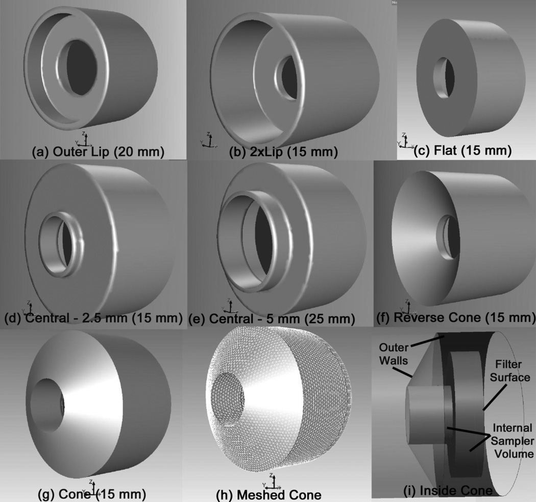
Each of the seven face geometries are illustrated in Figure 1, showing only one sampler inlet size per geometry. Five sets of modifications were made to the 37-mm CFC inlet by maintaining the current flat face but changing perimeter projections or "lips" on the cap surface. The first modification replaced the central 4 mm inlet (and its central lip) with a larger simple opening (referenced here as "Outer Lip"). The second modification extended the existing lip at the perimeter of the 37-mm CFC ("2xLip"), which was hypothesized to reduce the sampler efficiency for larger particles. A third modification eliminated the lip at the perimeter of the current sampler, resulting in a flat cap similar to the previously investigated PHISH sampler(18) ("Flat"); this cap was hypothesized to increase the large particle aspiration, as particles with downward trajectories were no longer removed by impaction at the lip. The next two modifications positioned a thin lip at the perimeter of the sampler entry, similar to the way the internal cassette of the IOM extends beyond the solid face of the sampler body. To examine whether the amount of projection of this lip significantly affected sampler performance, this lip extended 2.5 mm (Central-2.5 mm) and 5 mm (Central-5 mm) in front of the flat modified cap.
FIGURE 1.
Representative sampler inlet shapes (a through g) with illustration of meshed surface (h) and internal structure of sampler (i). Parenthetical values indicate the diameter of the inlet opening. Each sampler inlet design (a–g) was modeled with 15, 20, and 25 mm opening sizes.
Two additional cap modifications were examined: one where the surface was no longer flat but cone-shaped ("Cone"), similar to the GSP sampler, and one reverse-cone shape. The insides of these two cap shapes were assumed solid to minimize the potential particle deposition on the interior surface of the sample cap. The slope of all cone walls were identical, thus the distance the cone projected outward from the inlet changed with the pore diameter. Heights of the cone were 15.8, 12.9, and 10.3 mm for the 15, 20, and 25 mm opening, respectively. Although thin-walled at the tip, these cone shapes did not meet the design criteria for isokinetic samplers; the range of velocities into the cone opening was 0.3 to 0.9 m s−1 for a 10 L min−1 sampling rate. For the reverse cone inlets, the overall height of the external wall was maintained at 10 mm, resulting in changes to the internal wall slope between opening sizes, as the exterior sampler surface was maintained at a constant diameter (42.4 mm) through all samplers in this study.
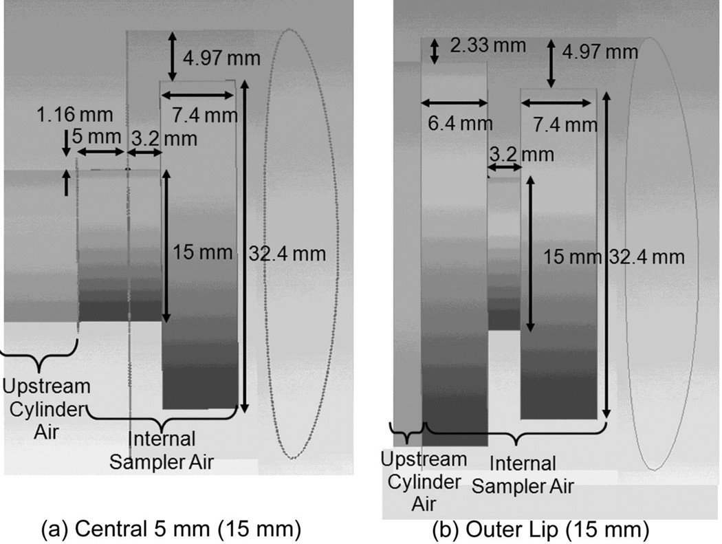
All remaining dimensions were matched to the two-piece, 37-mm cassette (Figure 2). Previous modeling of the PHISH sampler(11) used a 3-piece assembly so that a traditional pre-weighed cassette could be obtained from an analytical lab and the cap replaced by the hygienist with minimal filter handling. However, due to the increased awareness of particle deposition inside the walls of CFCs, the current design was made with the long-term intention of making internal capsules, configured to match the new opening design, which can be weighed and digested for metals analyses.(12) Therefore, the center ring of the 3-piece cassette was eliminated. In total, seven face designs, each with three pore opening dimensions, were investigated, for a total of 21 distinct sampler geometries.
FIGURE 2.
Sampler dimensions for (a) Central-5 mm and (b) Outer Lip, both with 15 mm single pore openings. The figures are oriented with air entering the sampler from the left. The outermost lines indicate the solid exterior surface of the sampler; the right-most elliptical shape is the junction of the sampler with the elliptical torso.
Simulation Geometries and Mesh Volume
Ansys software (Ansys, Inc., Lebanon, NY, USA) was used to generate the geometry and meshes. Figures 1(i) and 2 illustrate the internal volume of three of the 21 sampler configurations. The sampler exit was simplified by terminating the air volume at the filter plane (the right side of the internal volume in the figures), at which velocity equivalent to the 10 L min−1 flow rate were assigned. In previous work,(11) this simplification did not affect estimates of sampler efficiency, but it did affect where particles terminate within the sampler. The latter effect, which could lead to quantification of internal wall losses within the sampler, however, was not necessary to the objectives of this initial study: for these simulations, sampler collection efficiency was computed using all particles entering the sampler interior, regardless of its location of deposition. The interior dimensions (32.44 mm diameter, 7.4 mm depth) and wall thicknesses (4.97 mm walls, 3.21 mm cap for flat caps) of the simulated sampler were based on the standard 37-mm CFC (Figure 2).
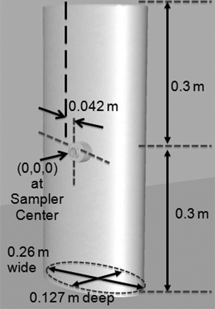
These samplers were positioned on a simple elliptical cylinder (Figure 3) to represent the human torso’s bluff body and were oriented horizontally (no downward angle) and positioned so that the sampler opening was facing into the oncoming wind. Investigation at +/−90° orientations, equivalent to a worker’s “side to the wind”, were also examined for a subset of these sampler inlet designs following the facing-the-wind evaluation. The torso was dimensioned to the 50th percentile female (U.S.) underarm dimensions, similar to the torso in human aspiration study simulations(13); the height was truncated at approximately hip height, to minimize the computational size of the simulations. To represent actual positioning of samplers on workers, each sampler was positioned so that the center of the opening was 0.042 m off of the torso centerline to represent positioning the sampler on a worker’s left lapel.
FIGURE 3.
Dimensions of cylindrical "torso" with details of sampler position. The lateral offset of the sampler is 0.042 m from the torso, center to center. The sampler illustrated is the thin central lip with 5 mm projection and 20 mm opening.
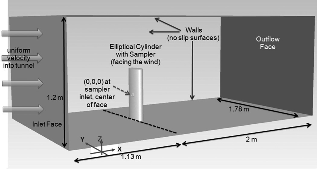
A simulated wind tunnel was positioned around the torso-sampler body, with the origin (0,0,0 m) positioned at the plane of the sampler opening (Figure 4). The wind tunnel extended more than four diameters upstream of the body, sufficient to ensure adequate flow development from the assigned uniform velocity into the domain. The tunnel also extended more than 10 diameters downstream to allow the outflow boundary (no acceleration) condition to be assigned at the domain exit. The cross sectional area of the wind tunnel was 1.78 m width by 1.2 m height, which resulted in a 7% blockage ratio (15% over torso height only); this was set to allow sufficient distance between the sampler and walls to minimize boundary effects of the wall interfering with fluid estimates near the sampler. Once surface geometries were generated, the domain was divided into three air volumes: the volume inside the sampler, a small cylindrical volume just upstream of the sampler (to control mesh refinements, located to the left of the sampler air volume in Figure 2), and the remaining wind tunnel domain. The node spacing on edges and surfaces were assigned similarly for each geometry and were based on the most refined mesh in previous sampler simulation studies.(11) In this previous sampler study, non-linear convergence tests identified that solutions with global solution errors of 2×10⁻⁵ resulted in changes ≥2.3% for all degrees of freedom, and mesh independence, using three-mesh error norms, was confirmed at mesh densities less refined than the mesh applied here. Surfaces and volumes were meshed with triangular and tetrahedral schemes, respectively. Although the changes to sampler dimensions resulted in minor differences in node positions between simulations, the final mesh density for these geometries were on the order of 2 million nodes.
FIGURE 4.
Computational domain, representing sampler positioned on elliptical torso positioned in wind tunnel, facing the wind.
Fluid Simulations
Fluent software (V13.0, Ansys Inc.) was used first to solve equations of fluid flow and then to simulate particle trajectories. For all sampler geometries, simulations examined freestream velocity of 0.2 m s−1 (assigned to the wind tunnel entrance) and flow rate through the sampler filter at 10 L min−1 (0.2 m s−1, assigned to the filter surface). Additional investigations were made for 0.1 and 0.4 m s−1 and for sampler flow rates of 8 L min−1 for a subset of geometries to investigate sensitivity of these parameters to sampler efficiency. All solid surfaces were modeled as "walls", with zero velocity at these surfaces. Throughout the domain, initial conditions equivalent to the freestream velocity (Ux=0.2, Uy=Uz=0 m s−1) and turbulence equivalent to 10% turbulence intensity with Ru=10 (K=6×10⁻⁴ m2 s−2; E=2.12×10⁻⁴ m2 s−3) were assigned. Steady-state, standard k-epsilon turbulence models, with standard wall functions and full buoyancy, were used to solve the fluid flow field for six degrees of freedom at each of the nodes: streamwise velocity (Ux), lateral velocity (Uy), vertical velocity (Uz), turbulence kinetic energy (K), dissipation of turbulence (E), and pressure (P). The solution methods employed the SIMPLE pressure-velocity coupling, with second-order upwind spatial discretization for momentum and turbulence parameters and standard discretization for pressure. Solutions were obtained when the iterative solver achieved global solution error (GSE) tolerance levels of 10−3, 10−4, 10−5, and 5×10⁻⁶, at which times solutions were saved and data extracted at 2205 positions upstream of the sampler to evaluate convergence. Non-linear iteration convergence was assessed by computing L2 error norms for each degree of freedom between successively smaller GSE values within a given mesh, and all simulations had L2 error norms below 1% at 10−5 GSE level, below the 5% target that was established a priori. (Details available in on-line supplemental materials.)
Particle Simulations and Sampler Efficiency Calculations
Once fluid flow simulations were adequately converged, particle simulations were conducted to identify upstream areas within which all particles would travel through the freestream and enter into the sampler. Particle simulations were conducted on solutions from 10−5 GSE tolerances. Particles were released with a horizontal velocity component equivalent to the freestream and a downward vertical component equivalent to the particle’s terminal settling velocity. The terminal settling velocity was computed from:
| (2) |
where: ρp is particle density (1000 kg m−3), g is gravitational acceleration (9.81 m s−2), and µ is the air viscosity (1.81×10⁻⁵ N s m−2). Non-evaporating, unit density, spherical particles with aerodynamic diameters of 1, 7, 26, 50, 74, 100, and 116 µm were simulated to cover the range of inhalable particles. Spherical drag law was used to compute the drag coefficient,(14) for which drag coefficients change by particle Reynolds number. Release positions and counts of particles that traveled into the sampler were used to identify the upstream critical area, as defined by Anthony and Flynn.(15) In short, particles were released along vertical line releases in sets of 100, across 0.01 m heights (ΔZ=0.0001 m) with lateral stepping of ΔY=0.00025 m. The size of the critical area was computed using the combination of position and count of particles trapped (Ntrapped), using equation 3:
| (3) |
Discrete-phase modeling was used to track particles, using a laminar tracking scheme, with automated implicit low-order and trapezoidal high-order schemes with 1 µm length scale. Accuracy control was set to a tolerance of 10−6 and maximum per-step refinement of 20; these factors were evaluated by decreasing values stepwise from defaults until a representative set of particle trajectories were no longer changed by the tolerance values used in the code. To examine sensitivity of the sampler to secondary aspiration associated with particle bounce, two coefficients of restitution (CoR) were assigned to the external sampler surfaces: 1.0, which assumes 100% of the energy of the particle impacting the surface is retained by the particle after the impact, and 0.8, a more realistic value for solid particles striking a plastic surface, to match the current CFC sampler materials. Critical areas for both assigned values were obtained.
Once critical areas were identified and their surface areas computed (Acritical), the sampler efficiency fraction (Es) was calculated using the equation for human aspiration simulations(15):
| (4) |
where Ucritical was the freestream velocity within the critical area, Asampler was the area of the sampler inlet, and Usampler was the velocity across that sampler inlet area.
Data Analysis
Descriptive statistics (to evaluate physically relevant differences) and ANOVA analysis with Tukey multiple comparisons (to evaluate statistical significance) were used to compare sampler efficiencies between inlet shape and opening size across all particle sizes. The sensitivity of the model's assignment of CoR on sampler aspiration estimations was examined using similar methods. For a limited number of sampler inlet designs, evaluations of sampler flow rate (8 vs 10 L min−1) and freestream velocity (0.1, 0.2, and 0.4 m s−1) on aspiration estimates were also examined to determine whether trends identified in the baseline condition (10 L min−1, 0.2 m s−1) were consistent across reasonable variation anticipated in work environments. Since comparisons to the IPM criterion or omni-directional human efficiency studies require these samplers be rotated around 360° relative to the oncoming wind, direct comparison to these performance criteria are ill-advised. However, comparisons between our estimates of sampler efficiencies and previous experimental and simulation data were made to identify the sampler that performed most like human aspiration efficiency estimates in facing-the-wind orientation. The sampler inlet design(s) with the best agreement with reported human aspiration efficiency trends and with the least sensitivity to sample flow rate were identified and prioritized for future investigations.
Results and Discussion
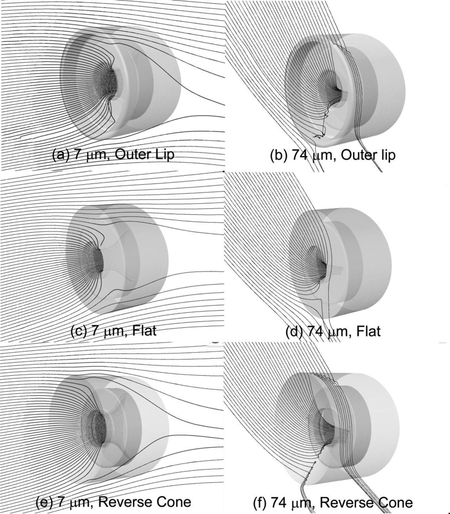
Figure 5 illustrates particle transport into three samplers, each with 15-mm pore openings, using baseline simulation settings (10 L min−1, 0.2 m s−1, CoR=1.0). All images were generated with particles released 0.75 m upstream (X) of the sampler opening, at 0.03 m off of the sampler centerline (Y=0.03 m), with a line release 0.06 m in height. These illustrations are coarser than those used to compute sampler efficiency but allow illustration of general particle behaviors. For the small (7 µm) particles, 60 particles were released over vertical positions (Z) 0.06 to 0.0 m below the sampler center position. Trajectories were mostly horizontal, with a slightly upward component consistent with flow approaching a bluff body. The small particles that reached the face of the sampler surface were capable of following airflow into each of these samplers. However, larger particles, illustrated on the right of this figure, traveled with significant downward velocity. For these images, 40 particles were released over vertical positions (Z) from 0.58 to 0.64 m above the sampler center. Near the tops of both the Outer Lip (5b) and the Reverse Cone (5f) inlet caps, the projections of the lip and the "reverse cone" walls prevented particles from entering into the sampler, as particles bounced on the outer surface and were transported away from the sampler inlet. Particles approaching the bottom of these inlet caps had sufficient downward momentum that resulted in bounces causing movement away from the sampler inlet.
FIGURE 5.
Trajectories of unit density particles released upstream within the critical areas of the (a, b) Outer Lip, (c, d) Flat, and (e, f) Reverse Cone sampler heads, each with 15-mm single pore opening. On the left are 60 trajectories of 7 µm particles, and on the right are 40 trajectories of 74 µm particles.
Sampler efficiency data are summarized in Table I for inlet designs at 10 L min−1 flow, 0.2 m s−1 freestream, and CoR=1.0. (On-line supplemental data provide results for CoR=0.8 and other velocity conditions tested.) All inlet designs had high sampling efficiency for small particles, with the anticipated trend of reduced sampling efficiency as particle size increased (ANOVA p < 0.001), with significant differences identified only with particles larger than 50 µm. Multiple comparison tests clearly identified differences in efficiency between sampler designs (p < 0.001). Tukey groupings identified similarities between the Cone, Flat, and two Central-lip samplers, identified with the highest efficiencies. In addition, the Outer Lip and the Reverse Cone performed similarly to one another and had lower efficiencies compared to the previous group. The 2xLip sampler was identified with a significantly reduced efficiency compared to all other sampler inlets.
TABLE I.
Sampler efficiency fraction for CoR=1.0 simulations, by particle size, for seven sampler inlet caps at three inlet opening sizes (15, 20, and 20 mm).
| Particle size, µm |
Outer Lip | 2x-lip | Flat | Central-5 mm | Central-2.5 mm | Cone | Reverse Cone | ||||||||||||||
|---|---|---|---|---|---|---|---|---|---|---|---|---|---|---|---|---|---|---|---|---|---|
| 15 | 20 | 25 | 15 | 20 | 25 | 15 | 20 | 25 | 15 | 20 | 25 | 15 | 20 | 25 | 15 | 20 | 25 | 15 | 20 | 25 | |
| 1 | 1.00 | 1.00 | 1.00 | 1.00 | 1.00 | 1.01 | 1.00 | 0.99 | 1.00 | 1.00 | 1.01 | 1.00 | 1.00 | 1.00 | 1.00 | 1.00 | 1.00 | 1.00 | 1.00 | 1.01 | 1.01 |
| 7 | 1.00 | 1.00 | 1.00 | 1.01 | 1.01 | 1.01 | 1.00 | 1.00 | 1.00 | 1.01 | 1.01 | 1.00 | 1.01 | 1.01 | 1.01 | 1.01 | 1.00 | 1.00 | 1.01 | 1.01 | 1.00 |
| 26 | 0.99 | 0.99 | 0.99 | 0.94 | 0.94 | 0.94 | 1.01 | 1.01 | 1.01 | 1.00 | 1.01 | 1.00 | 1.01 | 1.00 | 1.00 | 1.02 | 1.02 | 1.02 | 0.98 | 0.98 | 0.97 |
| 50 | 0.89 | 0.90 | 0.89 | 0.70 | 0.73 | 0.72 | 1.00 | 1.00 | 1.01 | 0.98 | 0.98 | 0.98 | 0.98 | 0.98 | 0.99 | 1.04 | 1.04 | 1.04 | 0.87 | 0.86 | 0.83 |
| 74 | 0.71 | 0.71 | 0.70 | 0.41 | 0.40 | 0.37 | 0.90 | 0.90 | 0.91 | 0.88 | 0.90 | 0.87 | 0.89 | 0.91 | 0.90 | 1.01 | 1.02 | 1.01 | 0.71 | 0.70 | 0.63 |
| 100 | 0.42 | 0.42 | 0.42 | 0.05 | 0.03 | 0.04 | 0.67 | 0.69 | 0.71 | 0.66 | 0.70 | 0.67 | 0.65 | 0.69 | 0.69 | 0.85 | 0.87 | 0.85 | 0.46 | 0.45 | 0.41 |
| 116 | 0.21 | 0.24 | 0.27 | 0.00 | 0.00 | 0.00 | 0.48 | 0.54 | 0.62 | 0.47 | 0.53 | 0.59 | 0.47 | 0.52 | 0.59 | 0.73 | 0.79 | 0.81 | 0.26 | 0.24 | 0.22 |
Results for the 2xLip sampler demonstrated that extension of the lip at the outer edge of the sampler significantly reduced aspiration for particles larger than 50 µm (p=<0.001, mean difference in efficiency fraction = 0.16). The Reverse Cone performed similar to the Outer Lip sampler (p=0.15, mean difference = 0.01). Other inlet designs, however, had significantly larger sampling efficiencies compared to the Outer Lip (p < 0.001), with the Cone shape aspirating significantly more particles than both the Outer Lip (mean difference = 0.21) and the Flat entry cap (mean difference 0.08). Although statistically significant differences in performance were identified between the Flat sampler and both Central samplers (p=0.003), the mean difference in sampler efficiency was 0.01 (standard deviation [sd]=0.015), a negligible change in performance relative to field aerosol study uncertainties. Examination of differences in the length of the Central thin lip's protrusion, in the range of reasonable differences in manufacturing processes (2.5 mm), identified little effect on sampler performance estimates (p=0.135, with mean difference = 0.00, sd=0.009) at this baseline condition.
The diameter of the sampler inlet had little effect on sampler efficiency (ANOVA, p=0.91). To maintain the same 10 L min−1 through samplers with different inlet diameters, larger diameter openings had a lower face velocity; in isokinetic sampler theory, this would result in increased sampling efficiency for the slower moving air. With the exception of the two samplers that performed less efficiently than the Outer Lip inlet design, increased inlet diameter resulted in increased sampler efficiency, within a sampler type (mean increase of 0.02), consistent with this theory. The largest effect of increased sampling efficiency by inlet diameter was generally seen in the largest particle size investigated (116 µm), where a change in the sampler opening from 15 to 25 mm resulted in sampler efficiency increases of 0.12 and 0.14 for the Central lip and Flat inlet designs, respectively. Because of concerns regarding the IOM's ability to aspirate particles larger than 100 µm, the upper limit of the inhalability definition, samplers enhancing the collection of these ultra-large particles should be less favorable than other designs. Hence, the sampler inlet diameter of 15 mm is perhaps the best recommendation to minimize the possibility of oversampling particles larger than 100 µm.
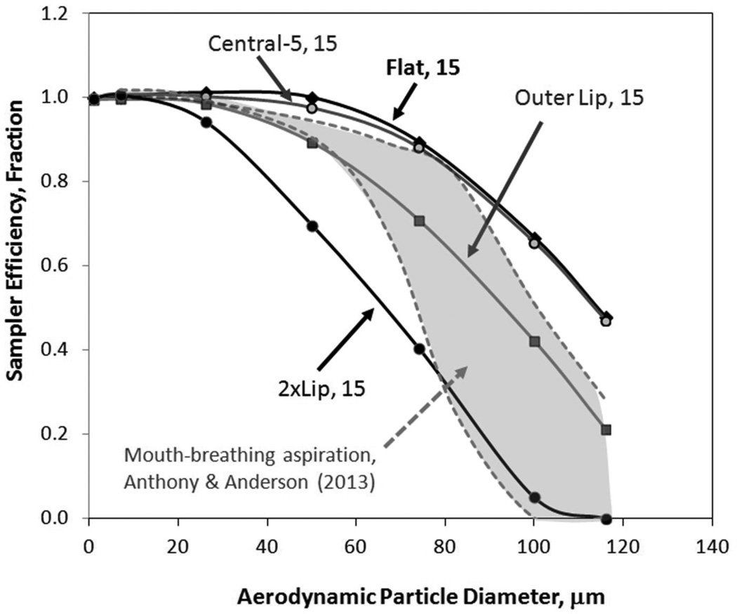
Figure 6 compares representative sampler efficiencies to human aspiration efficiency at similar facing-the-wind orientation and low freestream velocities (0.2 m s−1) using mouth-breathing(16) and nose-breathing(17) CFD simulation studies. The shaded region, outlined in dashes, represents heavy (50.3 L min−1, upper bound) and at-rest (7.5 L min−1, lower bound) mouth breathing, with nose breathing aspiration contained between these two bounds. The methods to compute aspiration and sampler efficiencies were similar between this current study and the comparative human-breathing modeling studies. Hence, biases that may exist in both CFD approaches are anticipated to be similar between studies, making comparisons between them attractive. As seen in Figure 6, the 2xLip inlet cap under-sampled across the majority of the inhalable particle size range but provided a good fit to the human aspiration estimates for large particles. The performance of the Flat and Central-5 mm sampler were reasonably similar to one another, but both over-sampled relative to the human aspiration CFD models. The Outer Lip design, with the simplest modification to the 37-mm sampler inlet (e.g., created by simply cutting a hole in the sampler cap), performed within the range of human aspiration efficiency across all particle sizes. This supports earlier hypothesis of researchers who used CFC samplers in the field with the simple modification of a large central hole to replace the 4mm inlet with adjacent lip as an easy surrogate for an inhalable sampler.(6–9)
FIGURE 6.
Sampler efficiency comparison to human aspiration models. The gray region outlined in dashes represents human aspiration efficiencies for facing-the-wind simulations from Anthony and Anderson (2013) at 0.2 m s−1 freestream velocity.
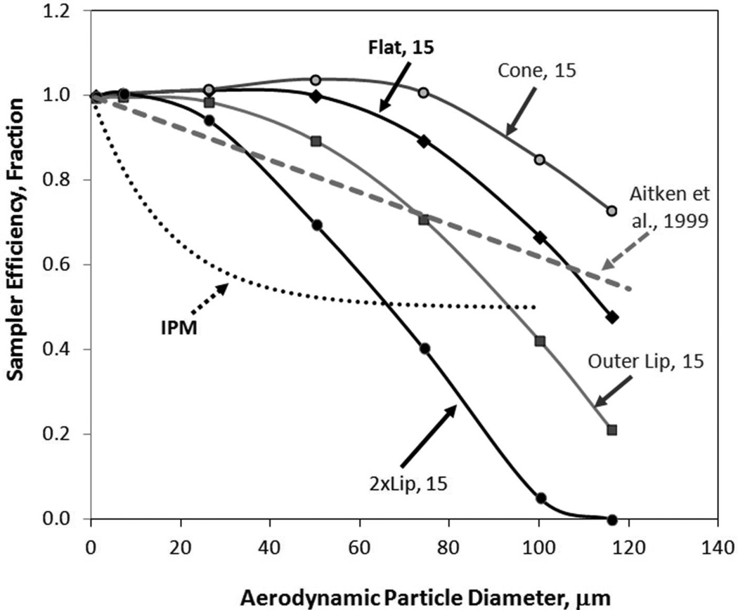
Comparison of our forward-facing sampling efficiency data to omni-directional data allows for the determination of designs that clearly underperform relative to omni-directional human aspiration estimates from mannequin studies. Since both sampler and human aspiration efficiency studies report that the maximum aspiration over all rotation angles occurs in the facing-the-wind orientation, samplers that underperform in the facing-the-wind orientation can be discounted at this stage of design. Figure 7 illustrates sampler efficiencies of representative inlet caps, facing the wind, compared to the current IPM sampler criterion(1) and the Aitken et al.(18) proposed low-flow inhalable criterion, recommended for environments with velocities 0.2 m s−1 and below. All samplers in the facing-the-wind orientation over-aspirated relative to both sampler performance recommendations for particles 26 µm and smaller. For larger particles, efficiencies for the 2xLip design were below the Aitken recommendation. When the sampler/torso assembly is rotated, the efficiency is anticipated to be further reduced. The performance of the 15 mm entry diameter Outer Lip inlet under-aspirated particles larger than 74 µm, which may be problematic at other rotations as well. Samplers with the Flat, Cone, and Central lip inlet caps over-aspirated relative to the omni-directional low velocity performance recommendation.
FIGURE 7.
Facing-the-wind sampler efficiency comparison to omnidirectional inhalable particulate mass sampling criteria. While samplers are not expected to meet these omnidirectional criteria, samplers underperforming at the facing-the-wind orientation are presumed to undersample when rotated and averaged over all orientations.
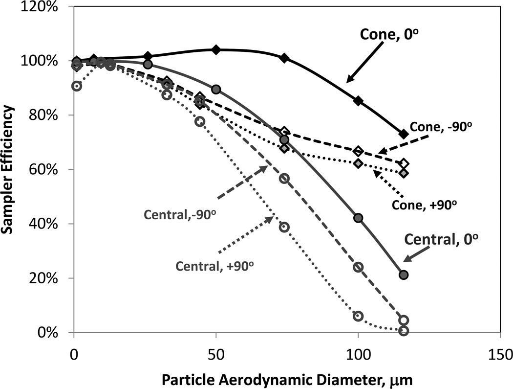
Following this finding, additional simulations were performed with the sampler-torso surrogate rotated +/−90° to assess whether these same trends were apparent at other orientations. Figure 8 identifies the sampling efficiency for the Cone and Central lip inlet caps at the three orientations. The sampler efficiency of the Cone shape exceeded that of the Central lip inlet cap, matched on each orientation angle. When the sampler was on the upstream side of the surrogate torso (−90°), the sampling efficiency was larger than when it was on the downstream side (+90°), where particles were required to cross the torso prior to being aspirated into the sampler. While the Cone had larger sampling efficiencies than the Central lip inlet across each of the three orientations relative to the oncoming wind, additional simulations to further examine orientation effects should consider a more realistic human form, as flow around the human shape (neck, head, and torso) becomes more important with rotation away from facing-the-wind.
FIGURE 8.
Sampler efficiency of inlet caps with Cone shape and Central lip (both 15 mm inlet diameters) at facing the wind (0°) and rotated 90° to the right or left.
Sensitivity Evaluations
Changing the CoR from 1.0 (100% elastic collision) to 0.8 resulted in no significant reduction in sampler collection efficiency (ANOVA p =0.57). In practical terms, the maximum reduction in sampler efficiency fraction from the decreased coefficient was only 0.09 (Cone inlet shape, 25 mm opening, 116 µm particle), and the mean difference over all 147 paired efficiency estimates was 0.01 (sd=0.017). No difference in sampler efficiency was identified for particles smaller than 50 µm, and the majority of differences were seen for particles 100 and 116 µm.
Because air sampling equipment may exhibit reduced airflow over the course of a full-shift monitoring event, and because pressure drops across some filter materials may be prohibitive at 10 L min−1, a limited number of sampler inlets were examined to evaluate the sensitivity of their performances to decreased flow rate. Sampling efficiencies of the Central-5 mm (all inlet diameters) and the Central-2.5 mm (15 mm inlet) inlet caps were examined at both 8 and 10 L min−1 sampling rates. (Efficiencies provided in on-line supplemental materials.) Sampling efficiency decreased with reduced sampler flow rate (p= 0.017, using only matched conditions, 28 pairs), with the mean aspiration difference of 0.02 (sd=0.05). The two largest efficiency differences were for the 74 µm particles, between the Central-5 mm sampler with a 25 mm opening (0.09) and the Central-2.5 mm with 15 mm opening (0.20). While no differences in performance were identified between the Central-5 mm and the Central-2.5 mm inlets at 10 L min−1, differences identified between geometry at a slower sampling rate were apparent. The longer 5-mm central lip may be preferred to the 2.5-mm lip because its sampling efficiency demonstrated less dependence on sample flow rate, which indicates it may be less sensitive to potential operator errors.
A final sensitivity investigation examined the change in sampler performance with changes in freestream velocity. Although an ‘ideal’ sampler would perform identically in a variety of freestream velocities, it is understood that human aspiration efficiency of large particles is affected by changes in freestream velocity.(13,18,19) Recent low-velocity (< 0.2 m s−1) wind tunnel and computational studies report that omnidirectional human aspiration efficiency increases with decreasing freestream velocity, particularly for particles larger than 50 µm.(16,20) The sampling efficiencies of the Flat inlet cap (all opening sizes) and the Outer Lip (20 mm opening) were evaluated at freestream velocities of 0.1, 0.2 and 0.4 m s−1: for each sampler, the sampling efficiency increased with increased freestream velocity, (p=0.008), with the differences increasing with particle size. Thus, for the sampler designs that best met the human aspiration performance, the sampler efficiency trend was reverse that seen in omnidirectional human aspiration efficiency studies. Additional investigation of these behaviors in multiple low velocity test conditions should be examined in orientation-averaged investigations to understand potential bias that might be associated with the freestream velocity. While freestream velocities are often measurable in work environments, the actual magnitude is seldom controllable, so selecting a sampler inlet that is the least sensitive to freestream velocity over all orientations is desirable.
While this study identifies important factors that can enhance or reduce sampler efficiency, there are a few limitations to this evaluation of the effect of sampler shape on efficiency. First, CFD simulations relied on standard k-epsilon model, which, while robust in its ability to solve fluid flow fields, may poorly represent boundary layer effects in fluid simulations. Second, the oversimplification of the human torso with a surrogate cylinder may ignore fluid flow in the region of the head and neck, which ultimately result in significant particle transport differences. When the sampler-human is rotated so that the wind is from the back, small particles still move horizontally around the torso, but larger inhalable particles settle into the region near the sampler by passing around the neck and over the shoulder and, with increasing size, pass over the head. The simplified cylinder with a flat top and no “neck” may not be an adequate simplification for large particle transport at these “back-to-wind” orientations. Finally, this work was limited in orientation and wind speed: while sampler efficiency differences identified between sampler inlet designs were most significant for large (>50 µm) particles, these differences may be overwhelmed by the differences that may occur at other orientations and wind speeds. However, this study provides a baseline to identify favorable geometries on which to conduct improved simulations to account for these limitations in order to better represent particle transport through slow moving air into chest-mounted high flow samplers.
Conclusions
The sampler efficiencies of modifications to the standard 37-mm closed face cassette inlet cap were evaluated using CFD simulation tools. Although limited mostly to one orientation, three main findings are helpful to the design and testing of a new sampler inlet cap, for which omnidirectional studies are needed to compare to human aspiration efficiency data. First, although the inlet diameter was found to have significant but minor effects on particle collection efficiency, we identified that increasing the size of the inlet cap's entry could increase the sampler efficiency for particles larger than 100 µm: the smaller inlet area (15 mm) is recommended. Secondly, a perimeter "lip" that extends further than the current 6.4 mm in front of the 37 mm CFC inlet face significantly decreased the sampling efficiency, either by extending the current straight lip at the perimeter or by using a smoother entry shape, such as the reverse cone. With no perimeter lip, a thin lip positioned adjacent to the sampler inlet had fairly consistent performance over height of 0 (Flat) to 5 mm. However, sampler efficiencies with the shorter lip may be more sensitive to changes in sampler flow rate than the 5 mm thin Central lip. Finally, the Cone shape resulted in the largest particle collection efficiencies over the entire range of inhalable particle sizes. While it over-sampled relative to all other samplers and inhalable particulate mass sampling conventions when facing the wind, if omnidirectional studies of other sampler inlet designs result in underperformance, this cone shape may be worth investigating. Progression in a CFC inlet cap design modification should focus on the performance of the Outer Lip, Flat, and Central Lip samplers, with 15-mm sampler inlet diameters, over additional orientations relative to the oncoming wind, using a more realistic human shape (head, neck, torso) to evaluate agreement with human aspiration of inhalable particles in slow moving air.
Supplementary Material
Acknowledgements
This work was funded by grant R01OH010295 from the National Institute for Occupational Safety and Health. The authors wish to thank Kimberly Anderson, PhD, and Ben Getschman, MS, who assisted with simulations.
References
- 1.ACGIH. Threshold limit values for chemical substances and physical agents and biological exposure indices. Cincinnati, OH: American Conference of Governmental Industrial Hygienists; 2014. [Google Scholar]
- 2.Kenny LC, Aitken RJ, Chalmers C, Fabries JF, Gonzalez-Fernandez E, Kromhout H, Lidén G, Mark D, Riediger G, Prodi V. A collaborative European study of personal inhalable aerosol sampler performance. Ann. Occup. Hyg. 1997;41:135–153. doi: 10.1016/S0003-4878(96)00034-8. [DOI] [PubMed] [Google Scholar]
- 3.Kenny LC, Aitken RJ, Baldwin PEJ, Beaumont GC, Maynard AD. The sampling efficiency of personal inhalable aerosol samplers in low air movement environments. Journal of Aerosol Science. 1999;30:627–638. [Google Scholar]
- 4.Gorner P, Simon X, Wrobel R, Kauffer E, Witschger O. Laboratory study of selected personal inhalable aerosol samplers. Ann Occup Hyg. 2010;54:165–187. doi: 10.1093/annhyg/mep079. [DOI] [PubMed] [Google Scholar]
- 5.Sleeth DK, Vincent JH. Performance study of personal inhalable aerosol samplers at ultra-low wind speeds. Ann Occup Hyg. 2012;56(2):207–220. doi: 10.1093/annhyg/mer089. [DOI] [PubMed] [Google Scholar]
- 6.Carlton G, Flynn M. Field evaluation of an empirical-conceptual exposure model. Applied Occupational and Environmental Hygiene. 1997;12(8):555–561. [Google Scholar]
- 7.Clinkenbeard R, et al. A field comparison of the IOM inhalable aerosol sampler and a modified 37-mm cassette. Applied Occupational and Environmental Hygiene. 2002;17(9):622–627. doi: 10.1080/10473220290095943. [DOI] [PubMed] [Google Scholar]
- 8.Tan Y, Flynn MR, Buller TS. A field evaluation of the impact of transfer efficiency on worker exposure during spray painting. Ann Occup Hyg. 2002;46(1):103–112. doi: 10.1093/annhyg/mef006. [DOI] [PubMed] [Google Scholar]
- 9.Carlton GN. The impact of a change to inhalable occupational exposure limits: Strontium chromate exposure in the U.S. Air Force. American Industrial Hygiene Association Journal. 2003;64(3):306–311. doi: 10.1080/15428110308984821. [DOI] [PubMed] [Google Scholar]
- 10.Koehler KA, Anthony TR, Van Dyke M, Volckens J. Solid versus liquid particle aspiration efficiency of three personal aerosol samplers. Ann. Occup. Hyg. 2012;56(2):194–206. doi: 10.1093/annhyg/mer077. [DOI] [PMC free article] [PubMed] [Google Scholar]
- 11.Anthony TR, Landazuri AC, Van Dyke M, Volckens J. Use of computational fluid dynamics for design and evaluation of a personal, high-flow inhalable sampler. Ann. Occup. Hyg. 2010;54(4):427–442. doi: 10.1093/annhyg/meq029. [DOI] [PMC free article] [PubMed] [Google Scholar]
- 12.Harper M, Ashley K. Acid-soluble internal capsules for closed-face cassette elemental sampling and analysis of workplace air. Journal of Occup and Env Hygiene. 2013;10:297–306. doi: 10.1080/15459624.2013.777310. [DOI] [PMC free article] [PubMed] [Google Scholar]
- 13.Anthony TR. Contribution of facial feature dimensions and velocity parameters on particle inhalability. Ann. Occup. Hyg. 2010;54(6):710–725. doi: 10.1093/annhyg/meq040. [DOI] [PMC free article] [PubMed] [Google Scholar]
- 14.Morsi SA, Alexander AJ. An investigation of particle trajectories in two-phase flow. J. Fluid Mech. 1972;55(2):193–208. [Google Scholar]
- 15.Anthony TR, Flynn MR. Computational fluid dynamics investigation of particle inhalability. Journal of Aerosol Science. 2006;37(6):750–765. [Google Scholar]
- 16.Anthony TR, Anderson KR. Computational fluid dynamics investigation of human aspiration in low velocity air: Orientation effects on mouth breathing simulations. Ann. Occup. Hyg. 2013;57(6):740–757. doi: 10.1093/annhyg/mes108. [DOI] [PMC free article] [PubMed] [Google Scholar]
- 17.Anderson KR, Anthony TR. Computational fluid dynamics investigation of human aspiration in low velocity air: Orientation effects on nose breathing simulations. Ann Occup Hyg. 2014;58(5):625–645. doi: 10.1093/annhyg/meu018. [DOI] [PMC free article] [PubMed] [Google Scholar]
- 18.Aitken RJ, Baldwin PEJ, Beaumont GC, et al. Aerosol inhalability in low air movement environments. J. Aerosol Sci. 1999;30(5):613–626. [Google Scholar]
- 19.Kennedy NJ, Tatyan K, Hinds WC. Comparison of a simplified and full-size mannequin for the evaluation of inhalable sampler performance. Aerosol Sci and Technology. 2001;35:564–568. [Google Scholar]
- 20.Sleeth DK, Vincent JH. Proposed modification to the inhalable aerosol convention applicable to realistic workplace wind speeds. Ann Occup Hyg. 2011;55(5):476–484. doi: 10.1093/annhyg/meq100. [DOI] [PubMed] [Google Scholar]
Associated Data
This section collects any data citations, data availability statements, or supplementary materials included in this article.


